2004 SUBARU FORESTER oil temperature
[x] Cancel search: oil temperaturePage 2345 of 2870

4AT-33
AUTOMATIC TRANSMISSION
Stall Test
5. Stall Test
A: INSPECTION
NOTE:
The stall test is of extreme importance in diagnos-
ing the condition of the automatic transmission and
the engine. It should be conducted to measure the
engine stall speeds in “R” and “2” ranges (when
HOLD switch is ON).
Purposes of the stall test:
To check the operation of the automatic trans-
mission clutch.
To check the operation of the torque converter
clutch.
To check engine performance.
1) Check that the throttle valve opens fully.
2) Check that the engine oil level is correct.
3) Check that the coolant level is correct.
4) Check that the ATF level is correct.
5) Check that the differential gear oil level is cor-
rect.
6) Increase ATF temperature to 70 — 80°C (158 —
176°F) by idling the engine for approximately 30
minutes (with select lever set to “N” or “P”).
7) Place the wheel chocks at the front and rear of
all wheels and engage the parking brake.
8) Shift the manual linkage to ensure it operates
properly, then shift the select lever to the “2” range
and turn the HOLD switch to ON.
9) While forcibly depressing the foot brake pedal,
gradually depress the accelerator pedal until the
engine operates at full throttle.
10) When the engine speed is stabilized, record
that speed quickly and release the accelerator ped-
al.
11) Shift the select lever to “N” range, and cool
down the engine by idling it for more than one
minute.12) If the stall speed in “2” range (with HOLD switch
ON) is higher than specifications, low clutch slip-
ping and “2-4 brake slipping” may occur. To identify
it, conduct the same test as above in “R” range.
13) Perform the stall tests with the select lever in
the “D” range.
NOTE:
Do not continue the stall test for more than five
seconds at a time (from closed throttle, fully open
throttle to stall speed reading). Failure to follow this
instruction causes the engine oil and ATF to deteri-
orate and the clutch and brake to be adversely af-
fected.
Be sure to cool down the engine for at least one
minute after each stall test with the select lever set
in the “P” or “N” range and with the idle speed lower
than 1,200 rpm.
If the stall speed is higher than the specified
range, attempt to finish the stall test in as short a
time as possible, in order to prevent the automatic
transmission from sustaining damage.
Stall speed (at sea level):
2.0 L NON-TURBO MODEL
2,000 — 2,500 rpm
2.0 L TURBO MODEL
2,600 — 3,300 rpm
2.5 L NON-TURBO MODEL
2,100 — 2,600 rpm
2.5 L TURBO MODEL
2,700 — 3,200 rpm
(A) Brake pedal
(B) Accelerator pedal
(A) (B)
P
R
N
D
3
2
1
AT-00449
Page 2348 of 2870
4AT-36
AUTOMATIC TRANSMISSION
Line Pressure Test
7. Line Pressure Test
A: MEASUREMENT
NOTE:
If the clutch or the brake shows a sign of slippage or
shifting sensation is not correct, the line pressure
should be checked.
Excessive shocks during upshifting or shifting
takes place at a higher point than under normal cir-
cumstances, may be due to the line pressure being
too high.
Slippage or inability to operate the vehicle may,
in most cases, be due to insufficient oil pressure for
the operation of the clutch, brake or control valve.
1) Line pressure measurement (under no load):
(1) Before measuring line pressure, jack-up all
wheels.
(2) Maintain the temperature of ATF at approx.
70 — 80°C (158 — 176°F) during measurement.
(ATF will reach the above temperature after
idling the engine for approx. 30 minutes with the
select lever in “N” or “P”.)
2) Line pressure measurement (under heavy load):
(1) Before measuring line pressure, apply both
foot and parking brakes with all wheels chocked
(Same as for “stall” test conditions).
(2) Measure the line pressure when the select
lever is in “D”, “2” (HOLD switch ON) with engine
under stall conditions.
(3) Measure the line pressure within 5 seconds
after shifting the select lever to each position. (If
the line pressure needs to be measured again,
allow the engine to idle and cool it down more
than 1 minute.)
(4) Maintain the ATF temperature at approx. 70
— 80°C (158 — 176°F) during measurement.
(ATF will reach the above temperature after
idling the engine for approx. 30 minutes with the
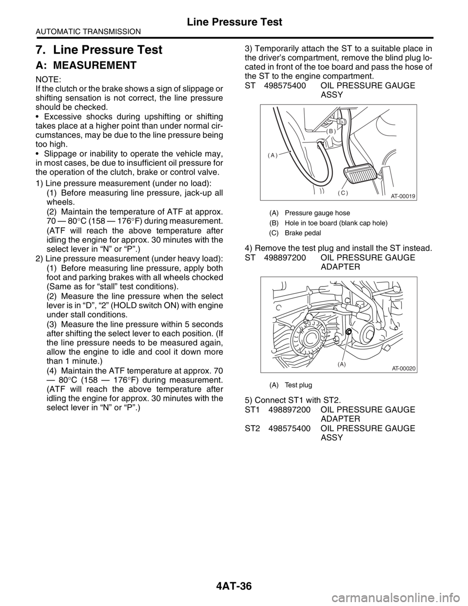
select lever in “N” or “P”.)3) Temporarily attach the ST to a suitable place in
the driver’s compartment, remove the blind plug lo-
cated in front of the toe board and pass the hose of
the ST to the engine compartment.
ST 498575400 OIL PRESSURE GAUGE
ASSY
4) Remove the test plug and install the ST instead.
ST 498897200 OIL PRESSURE GAUGE
ADAPTER
5) Connect ST1 with ST2.
ST1 498897200 OIL PRESSURE GAUGE
ADAPTER
ST2 498575400 OIL PRESSURE GAUGE
ASSY
(A) Pressure gauge hose
(B) Hole in toe board (blank cap hole)
(C) Brake pedal
(A) Test plug
AT-00019
(A)(B)
(C)
AT-00020(A)
Page 2369 of 2870
4AT-56
AUTOMATIC TRANSMISSION
Front Vehicle Speed Sensor
17) Lower the transmission jack.
NOTE:
Do not separate the transmission jack and trans-
mission.
18) Remove the ATF cooler inlet and outlet pipes.
CAUTION:
When removing the outlet pipe, be careful not
to lose the ball and spring used with retaining
screw.
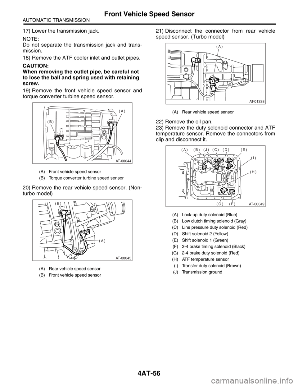
19) Remove the front vehicle speed sensor and
torque converter turbine speed sensor.
20) Remove the rear vehicle speed sensor. (Non-
turbo model)21) Disconnect the connector from rear vehicle
speed sensor. (Turbo model)
22) Remove the oil pan.
23) Remove the duty solenoid connector and ATF
temperature sensor. Remove the connectors from
clip and disconnect it.
(A) Front vehicle speed sensor
(B) Torque converter turbine speed sensor
(A) Rear vehicle speed sensor
(B) Front vehicle speed sensor
AT-00044
(A)
(B)
AT-00045
(A) (B)
(A) Rear vehicle speed sensor
(A) Lock-up duty solenoid (Blue)
(B) Low clutch timing solenoid (Gray)
(C) Line pressure duty solenoid (Red)
(D) Shift solenoid 2 (Yellow)
(E) Shift solenoid 1 (Green)
(F) 2-4 brake timing solenoid (Black)
(G) 2-4 brake duty solenoid (Red)
(H) ATF temperature sensor
(I) Transfer duty solenoid (Brown)
(J) Transmission ground
AT-01338
(A)
AT-00049
(A) (B) (J) (C) (D) (E)
(I)
(H)
(F) (G)
Page 2374 of 2870
4AT-61
AUTOMATIC TRANSMISSION
Control Valve Body
17.Control Valve Body
A: REMOVAL
1. NON-TURBO MODEL
1) Lift-up the vehicle.
2) Clean the transmission exterior.
3) Drain the ATF completely.
NOTE:
Tighten the drain plug (ATF) after draining the
ATF.
Always use new gasket.
Tightening torque:
25 N
⋅m (2.5 kgf-m, 18.1 ft-lb)
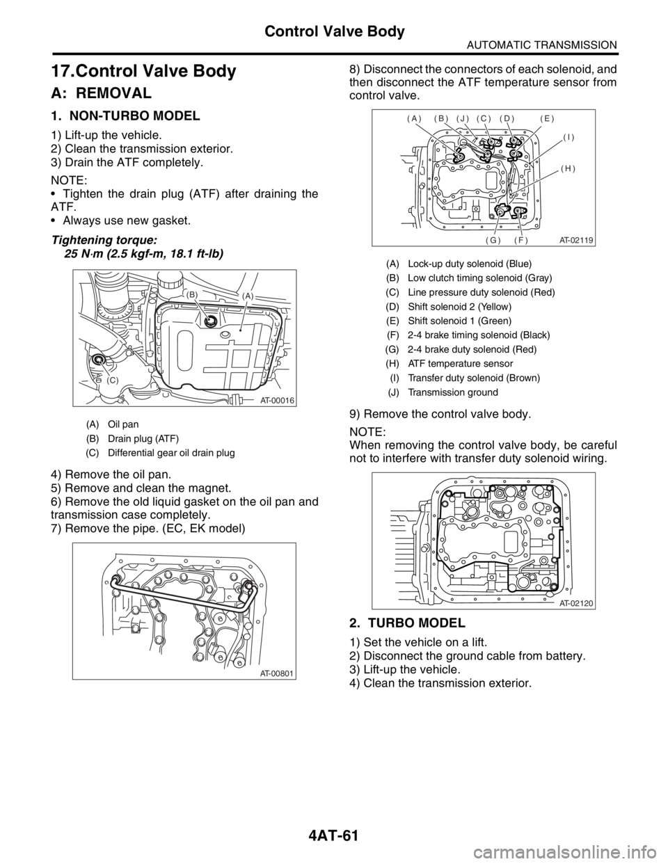
4) Remove the oil pan.
5) Remove and clean the magnet.
6) Remove the old liquid gasket on the oil pan and
transmission case completely.
7) Remove the pipe. (EC, EK model)8) Disconnect the connectors of each solenoid, and
then disconnect the ATF temperature sensor from
control valve.
9) Remove the control valve body.
NOTE:
When removing the control valve body, be careful
not to interfere with transfer duty solenoid wiring.
2. TURBO MODEL
1) Set the vehicle on a lift.
2) Disconnect the ground cable from battery.
3) Lift-up the vehicle.
4) Clean the transmission exterior.
(A) Oil pan
(B) Drain plug (ATF)
(C) Differential gear oil drain plug
AT-00016
(A) (B)
(C)
AT-00801
(A) Lock-up duty solenoid (Blue)
(B) Low clutch timing solenoid (Gray)
(C) Line pressure duty solenoid (Red)
(D) Shift solenoid 2 (Yellow)
(E) Shift solenoid 1 (Green)
(F) 2-4 brake timing solenoid (Black)
(G) 2-4 brake duty solenoid (Red)
(H) ATF temperature sensor
(I) Transfer duty solenoid (Brown)
(J) Transmission ground
AT-02119
(A) (B) (J) (C) (D) (E)
(I)
(H)
(F) (G)
AT-02120
Page 2376 of 2870
4AT-63
AUTOMATIC TRANSMISSION
Control Valve Body
B: INSTALLATION
1. NON-TURBO MODEL
1) Set the range select lever in “N” range.
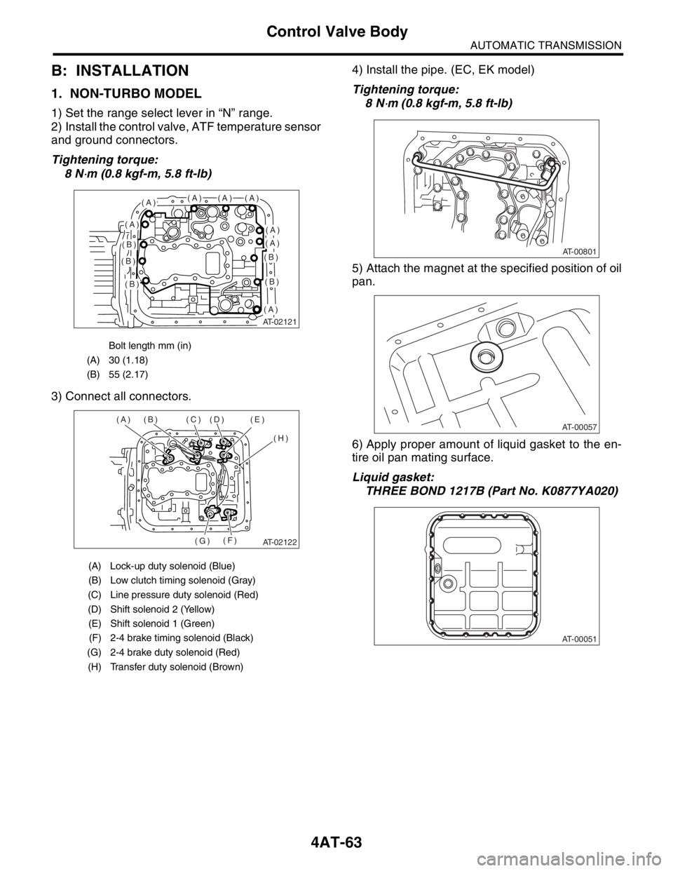
2) Install the control valve, ATF temperature sensor
and ground connectors.
Tightening torque:
8 N
⋅m (0.8 kgf-m, 5.8 ft-lb)
3) Connect all connectors.4) Install the pipe. (EC, EK model)
Tightening torque:
8 N
⋅m (0.8 kgf-m, 5.8 ft-lb)
5) Attach the magnet at the specified position of oil
pan.
6) Apply proper amount of liquid gasket to the en-
tire oil pan mating surface.
Liquid gasket:
THREE BOND 1217B (Part No. K0877YA020)
Bolt length mm (in)
(A) 30 (1.18)
(B) 55 (2.17)
(A) Lock-up duty solenoid (Blue)
(B) Low clutch timing solenoid (Gray)
(C) Line pressure duty solenoid (Red)
(D) Shift solenoid 2 (Yellow)
(E) Shift solenoid 1 (Green)
(F) 2-4 brake timing solenoid (Black)
(G) 2-4 brake duty solenoid (Red)
(H) Transfer duty solenoid (Brown)
AT-02121
(A)(A)(A)(A)
(A)(A)
(A)
(A)
(B)
(B)
(B)
(B)
(B)
AT-02122
(A) (B) (C) (D) (E)
(H)
(F)
(G)
AT-00801
AT-00057
AT-00051
Page 2384 of 2870
4AT-71
AUTOMATIC TRANSMISSION
Shift Solenoids, Duty Solenoids and ATF Temperature Sensor
19.Shift Solenoids, Duty Sole-
noids and ATF Temperature
Sensor
A: REMOVAL
1. SHIFT SOLENOID AND DUTY SOLE-
NOID
1) Lift-up the vehicle.
2) Clean the transmission exterior.
3) Drain the ATF completely.
4) Replace the gasket with new one, and then tight-
en the drain plug (ATF).
Tightening torque:
25 N
⋅m (2.5 kgf-m, 18.1 ft-lb)
5) Remove the oil pan.
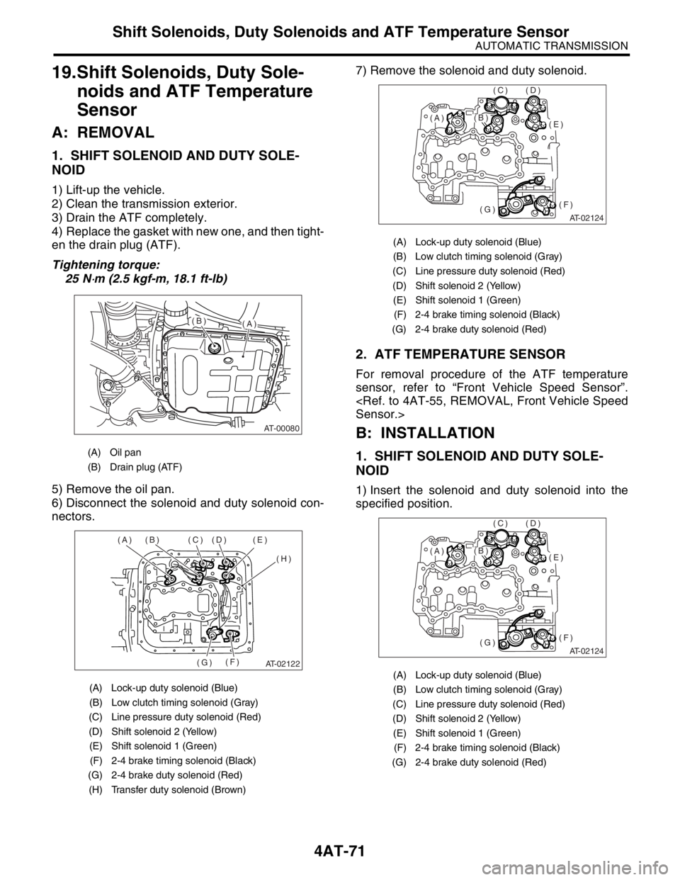
6) Disconnect the solenoid and duty solenoid con-
nectors.7) Remove the solenoid and duty solenoid.
2. ATF TEMPERATURE SENSOR
For removal procedure of the ATF temperature
sensor, refer to “Front Vehicle Speed Sensor”.
B: INSTALLATION
1. SHIFT SOLENOID AND DUTY SOLE-
NOID
1) Insert the solenoid and duty solenoid into the
specified position.
(A) Oil pan
(B) Drain plug (ATF)
(A) Lock-up duty solenoid (Blue)
(B) Low clutch timing solenoid (Gray)
(C) Line pressure duty solenoid (Red)
(D) Shift solenoid 2 (Yellow)
(E) Shift solenoid 1 (Green)
(F) 2-4 brake timing solenoid (Black)
(G) 2-4 brake duty solenoid (Red)
(H) Transfer duty solenoid (Brown)
AT-00080
(A)(B)
AT-02122
(A) (B) (C) (D) (E)
(H)
(F)
(G)
(A) Lock-up duty solenoid (Blue)
(B) Low clutch timing solenoid (Gray)
(C) Line pressure duty solenoid (Red)
(D) Shift solenoid 2 (Yellow)
(E) Shift solenoid 1 (Green)
(F) 2-4 brake timing solenoid (Black)
(G) 2-4 brake duty solenoid (Red)
(A) Lock-up duty solenoid (Blue)
(B) Low clutch timing solenoid (Gray)
(C) Line pressure duty solenoid (Red)
(D) Shift solenoid 2 (Yellow)
(E) Shift solenoid 1 (Green)
(F) 2-4 brake timing solenoid (Black)
(G) 2-4 brake duty solenoid (Red)
AT-02124
(E)
(F)(G)
(D)(C)
(B)(A)
AT-02124
(E)
(F)(G)
(D)(C)
(B)(A)
Page 2385 of 2870
4AT-72
AUTOMATIC TRANSMISSION
Shift Solenoids, Duty Solenoids and ATF Temperature Sensor
2) Tighten the bolt and nut.
Tightening torque:
8 N
⋅m (0.8 kgf-m, 5.8 ft-lb)
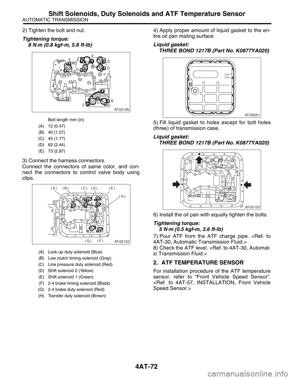
3) Connect the harness connectors.
Connect the connectors of same color, and con-
nect the connectors to control valve body using
clips.4) Apply proper amount of liquid gasket to the en-
tire oil pan mating surface.
Liquid gasket:
THREE BOND 1217B (Part No. K0877YA020)
5) Fill liquid gasket to holes except for bolt holes
(three) of transmission case.
Liquid gasket:
THREE BOND 1217B (Part No. K0877YA020)
6) Install the oil pan with equally tighten the bolts.
Tightening torque:
5 N
⋅m (0.5 kgf-m, 3.6 ft-lb)
7) Pour ATF from the ATF charge pipe.
8) Check the ATF level.
2. ATF TEMPERATURE SENSOR
For installation procedure of the ATF temperature
sensor, refer to “Front Vehicle Speed Sensor”.
Bolt length mm (in)
(A) 12 (0.47)
(B) 40 (1.57)
(C) 45 (1.77)
(D) 62 (2.44)
(E) 73 (2.87)
(A) Lock-up duty solenoid (Blue)
(B) Low clutch timing solenoid (Gray)
(C) Line pressure duty solenoid (Red)
(D) Shift solenoid 2 (Yellow)
(E) Shift solenoid 1 (Green)
(F) 2-4 brake timing solenoid (Black)
(G) 2-4 brake duty solenoid (Red)
(H) Transfer duty solenoid (Brown)
AT-02126
E
AD
EE
D
D
B
CC
AT-02122
(A) (B) (C) (D) (E)
(H)
(F)
(G)
AT-00051
AT-02123
Page 2472 of 2870

4AT(H4SO)-13
AUTOMATIC TRANSMISSION (DIAGNOSTIC)
Transmission Control Module (TCM) I/O Signal
Inhibitor
switch“2” range
switchB55 6Select lever in “2” range Less than 1
—
Select lever in any other
than “2” rangeMore than 8
“1” range
switchB55 7Select lever in “1” range Less than 1
—
Select lever in any other
than “1” rangeMore than 8
Brake switch B55 12Brake pedal depressed More than 10.5
—
Brake pedal released Less than 1
Kick-down switch B55 11Throttle fully opened Less than 1
—
Throttle fully closed More than 6.5
AT OIL TEMP warning light B56 10Light ON Less than 1
—
Light OFF More than 9
Throttle position sensor B54 3Throttle fully closed 0.2 — 1.0
—
Throttle fully open 4.2 — 4.7
Throttle position sensor
power supplyB54 2Ignition switch ON (with
engine OFF)4.8 — 5.3 —
ATF temperature sensor B54 11ATF temperature 20°C
(68°F)1.6 — 2.0 2.1 k — 2.9 k
ATF temperature 80°C
(176°F)0.4 — 0.9 275 — 375
Rear vehicle speed sensor B55 24Vehicle stopped 0
450 — 650
Vehicle speed at least 20
km/h (12 MPH)More than 1 (AC range)
Front vehicle speed sensor B55 18Vehicle stopped 0
450 — 650
Vehicle speed at least 20
km/h (12 MPH)More than 1 (AC range)
Torque converter turbine
speed sensorB55 8Engine idling after warm-
up (D range)0
450 — 650
Engine idling after warm-
up (N range)More than 1 (AC range)
Vehicle speed output signal B56 17Vehicle speed at most 10
km/h (6 MPH)Less than 1 ←
→ More than 4—
Engine speed signal B55 17Ignition switch ON (with
engine OFF)More than 10.5
—
Ignition switch ON (with
engine ON)8 — 11
Cruise set signal B55 22When cruise control is set
(SET lamp ON)Less than 1
—
When cruise control is not
set (SET lamp OFF)More than 6.5
Torque control signal 1 B56 5Ignition switch ON (with
engine ON)More than 4 —
Torque control signal 2 B56 14Ignition switch ON (with
engine ON)More than 4 —
Torque control cut signal B55 10Ignition switch ON
(After engine is warmed-up)8—
Intake manifold pressure
signalB54 1 Engine idling after warm-up 0.4 — 1.6 —
Shift solenoid 1 B54 221st or 4th gear More than 9
10 — 16
2nd or 3rd gear Less than 1
Shift solenoid 2 B54 51st or 2nd gear More than 9
10 — 16
3rd or 4th gear Less than 1 Check with ignition switch ON.
ContentConnector
No.Terminal No. Measuring conditions Voltage (V)Resistance
to chassis
ground (Ω)