2004 SUBARU FORESTER oil temperature
[x] Cancel search: oil temperaturePage 720 of 2870
RM-5
RECOMMENDED MATERIAL
Recommended Materials
4. FLUID
Use the fluids specified in the table below. Do not mix two different kinds or makes of fluid.
5. COOLANT
Use genuine coolant to protect the engine.
6. REFRIGERANT
Standard air conditioners on Subaru vehicles use HFC134a refrigerant. Do not mix it with other refrigerants.
Also, do not use any air compressor oil except for ZXL200PG.
7. GREASE
Use the grease and supplementary lubricants shown in the table below.
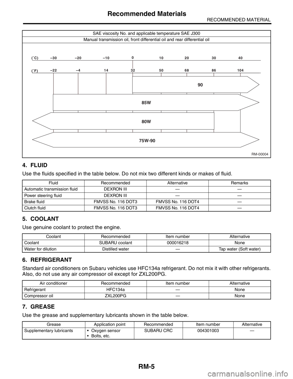
SAE viscosity No. and applicable temperature SAE J300
Manual transmission oil, front differential oil and rear differential oil
Fluid Recommended Alternative Remarks
Automatic transmission fluid DEXRON III — —
Power steering fluid DEXRON III — —
Brake fluid FMVSS No. 116 DOT3 FMVSS No. 116 DOT4 —
Clutch fluid FMVSS No. 116 DOT3 FMVSS No. 116 DOT4 —
Coolant Recommended Item number Alternative
Coolant SUBARU coolant 000016218 None
Water for dilution Distilled water — Tap water (Soft water)
Air conditioner Recommended Item number Alternative
Refrigerant HFC134a — None
Compressor oil ZXL200PG — None
Grease Application point Recommended Item number Alternative
Supplementary lubricants Oxygen sensor
Bolts, etc.SUBARU CRC 004301003 —
RM-00004 (F)–22 –4 14 50 68 86 104 (C)–30 –20 –100
10 20 30 40
85W
75W-9080W90
32
Page 736 of 2870

PI-13
PRE-DELIVERY INSPECTION
Pre-delivery Inspection
If any dampness in the compartment is discovered
after the water has been applied, carefully check all
areas that may have possibly contributed to the
leak.
45.APPEARANCE CHECK 2
1) When vehicle body is covered with protective
film (wrap guard), peel it off.
NOTE:
Use of steam eases peeling off the wrap guard.
When performing on the vehicles left for a long
time, or during low temperature period, sprinkle
some water heated to 50 — 60°C (122 — 140°F)
over the vehicle to raise its surface temperature be-
fore peeling off the wrap guard.
Do not use the water heated to over 60°C (140°F).
If the adhesive remains on the coated surface,
rub the portion with a flannel rag, etc. soaked with a
coat of coating wax or a solvent, such as oil ben-
zene and IPA, and then wipe it off.
Avoid adhesion of the solvent to resin or rubber
components. Do not use coating wax or a solvent
while the component surface temperature is high
due to hot weather, etc.
If the coated surface is swollen out due to seams
or moisture, expose the vehicle to the sun light for a
few hours. Otherwise, heat the portion with seams
or moisture using a dryer, etc.
Dispose of the peeled wrap guard as burnable in-
dustrial garbage.
2) Check the whole vehicle body for stains, flaking,
damage caused by transportation, rust, dirt, cracks,
or blistering.
NOTE:
It is better to determine an inspection pattern in
order to avoid missing an area, since the total in-
spection area is wide.
It is desirable not to make corrections to the body
paint unless absolutely needed. However, if any
corrections are required to remove scratches or
rust, the area to be corrected must be limited as
much as possible. Re-painting and spray painting
must be avoided whenever possible.
3) Carefully check each window glass for scratch-
es. Slight damage may be removed by polishing
with cerium oxide. (Half-fill a cup with cerium oxide,
and add warm water to it. Then agitate the content
until it turn to wax. Apply this wax to a soft cloth,
and polish the glass.)4) Check each portion of the vehicle body and un-
derside components for the formation of rust. If rust
is discovered, remove it with #80 — #180 emery
paper, and treat the surface with rust preventive.
After this treatment is completed, flush the portion
thoroughly, and prepare the surface for repair
painting.
5) Check each portion of the body and all of the
chrome parts for deformation or distortion. Also
check each lamp lens for cracks.
Page 745 of 2870
PM-8
PERIODIC MAINTENANCE SERVICE
Engine Oil
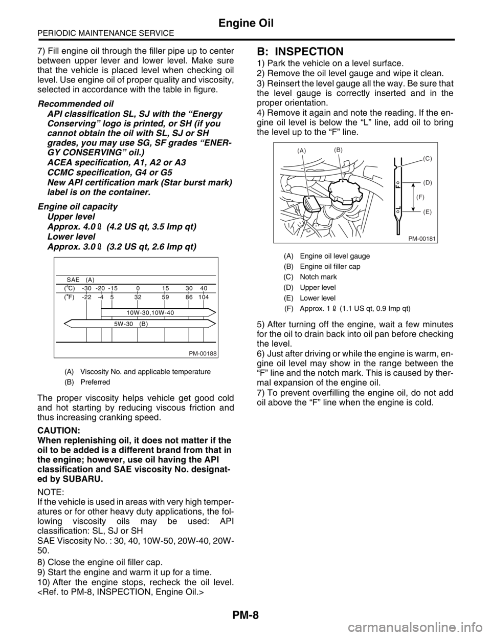
7) Fill engine oil through the filler pipe up to center
between upper lever and lower level. Make sure
that the vehicle is placed level when checking oil
level. Use engine oil of proper quality and viscosity,
selected in accordance with the table in figure.
Recommended oil
API classification SL, SJ with the “Energy
Conserving” logo is printed, or SH (if you
cannot obtain the oil with SL, SJ or SH
grades, you may use SG, SF grades “ENER-
GY CONSERVING” oil.)
ACEA specification, A1, A2 or A3
CCMC specification, G4 or G5
New API certification mark (Star burst mark)
label is on the container.
Engine oil capacity
Upper level
Approx. 4.02 (4.2 US qt, 3.5 Imp qt)
Lower level
Approx. 3.02 (3.2 US qt, 2.6 Imp qt)
The proper viscosity helps vehicle get good cold
and hot starting by reducing viscous friction and
thus increasing cranking speed.
CAUTION:
When replenishing oil, it does not matter if the
oil to be added is a different brand from that in
the engine; however, use oil having the API
classification and SAE viscosity No. designat-
ed by SUBARU.
NOTE:
If the vehicle is used in areas with very high temper-
atures or for other heavy duty applications, the fol-
lowing viscosity oils may be used: API
classification: SL, SJ or SH
SAE Viscosity No. : 30, 40, 10W-50, 20W-40, 20W-
50.
8) Close the engine oil filler cap.
9) Start the engine and warm it up for a time.
10) After the engine stops, recheck the oil level.
1) Park the vehicle on a level surface.
2) Remove the oil level gauge and wipe it clean.
3) Reinsert the level gauge all the way. Be sure that
the level gauge is correctly inserted and in the
proper orientation.
4) Remove it again and note the reading. If the en-
gine oil level is below the “L” line, add oil to bring
the level up to the “F” line.
5) After turning off the engine, wait a few minutes
for the oil to drain back into oil pan before checking
the level.
6) Just after driving or while the engine is warm, en-
gine oil level may show in the range between the
“F” line and the notch mark. This is caused by ther-
mal expansion of the engine oil.
7) To prevent overfilling the engine oil, do not add
oil above the “F” line when the engine is cold.
(A) Viscosity No. and applicable temperature
(B) Preferred
PM-00188
40 30 15 0 -15 -20 -30 ( C)
104 86 59 32
10W-30,10W-40 5 -4 -22 ( F)
SAE (A)
5W-30 (B)
(A) Engine oil level gauge
(B) Engine oil filler cap
(C) Notch mark
(D) Upper level
(E) Lower level
(F) Approx. 12 (1.1 US qt, 0.9 Imp qt)
PM-00181
(A)(B)
(D)
(E) (F)(C)
Page 763 of 2870
PM-26
PERIODIC MAINTENANCE SERVICE
ATF
16.ATF
A: INSPECTION
CAUTION:
The level of ATF varies with fluid temperature.
Pay attention to the fluid temperature when
checking ATF level.
1) Raise the ATF temperature by driving a distance
of 5 to 10 km (3 to 6 miles). Otherwise, idle the en-
gine to raise ATF temperature to 70 — 80°C (158
— 176°F) on Subaru Select Monitor.
TION, Subaru Select Monitor.>
2) Make sure the vehicle is level.
3) After selecting all positions (P, R, N, D, 3, 2, 1),
set the select lever in “P” range. Measure the ATF
level with the engine idling for one or two minutes.
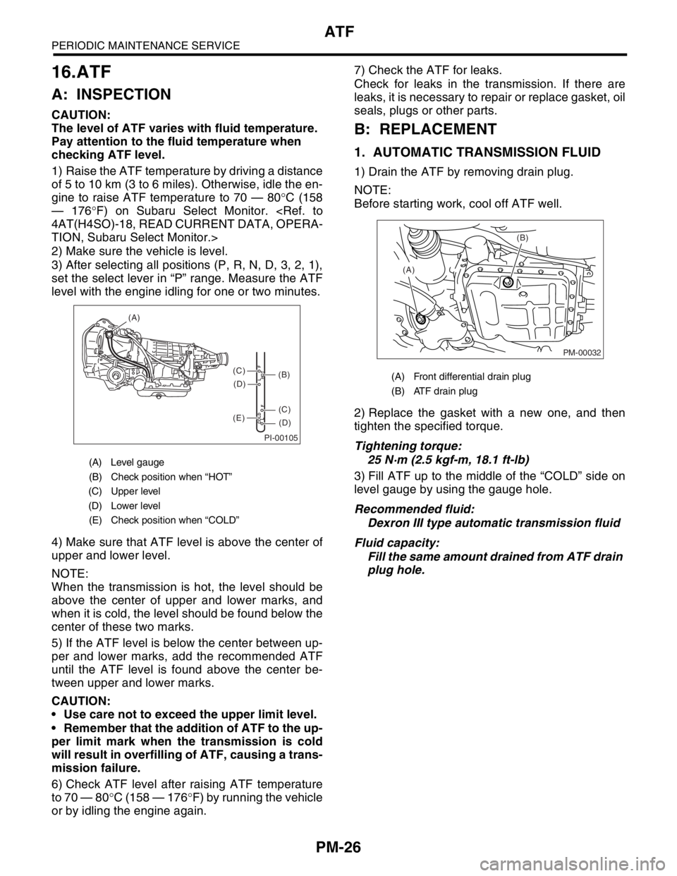
4) Make sure that ATF level is above the center of
upper and lower level.
NOTE:
When the transmission is hot, the level should be
above the center of upper and lower marks, and
when it is cold, the level should be found below the
center of these two marks.
5) If the ATF level is below the center between up-
per and lower marks, add the recommended ATF
until the ATF level is found above the center be-
tween upper and lower marks.
CAUTION:
Use care not to exceed the upper limit level.
Remember that the addition of ATF to the up-
per limit mark when the transmission is cold
will result in overfilling of ATF, causing a trans-
mission failure.
6) Check ATF level after raising ATF temperature
to 70 — 80°C (158 — 176°F) by running the vehicle
or by idling the engine again.7) Check the ATF for leaks.
Check for leaks in the transmission. If there are
leaks, it is necessary to repair or replace gasket, oil
seals, plugs or other parts.
B: REPLACEMENT
1. AUTOMATIC TRANSMISSION FLUID
1) Drain the ATF by removing drain plug.
NOTE:
Before starting work, cool off ATF well.
2) Replace the gasket with a new one, and then
tighten the specified torque.
Tightening torque:
25 N·m (2.5 kgf-m, 18.1 ft-lb)
3) Fill ATF up to the middle of the “COLD” side on
level gauge by using the gauge hole.
Recommended fluid:
Dexron III type automatic transmission fluid
Fluid capacity:
Fill the same amount drained from ATF drain
plug hole.
(A) Level gauge
(B) Check position when “HOT”
(C) Upper level
(D) Lower level
(E) Check position when “COLD”
PI-00105
COLD
LFHOT LF
(A)
(C)
(D)
(C)
(D)
(E)
(B)(A) Front differential drain plug
(B) ATF drain plug
PM-00032
(B)
(A)
Page 765 of 2870
PM-28
PERIODIC MAINTENANCE SERVICE
Front & Rear Differential Oil
17.Front & Rear Differential Oil
A: REPLACEMENT
1. FRONT DIFFERENTIAL (MT MODEL)
For MT model, manual transmission oil works as
differential oil to lubricate differential. Refer to
“Transmission Oil”.
2. FRONT DIFFERENTIAL (AT MODEL)
1) Drain the differential gear oil by removing drain
plug using TORX® T70.
CAUTION:
Before starting work, cool off differential gear
oil well.
If front differential gear oil adheres to the ex-
haust pipe, wipe it off completely.
2) Replace the gasket with a new one, and then
tighten the drain plug to specified torque.
Tightening torque:
Aluminum gasket:
44 N·m (4.5 kgf-m, 32.5 ft-lb)
Copper gasket:
70 N·m (7.1 kgf-m, 51.6 ft-lb)
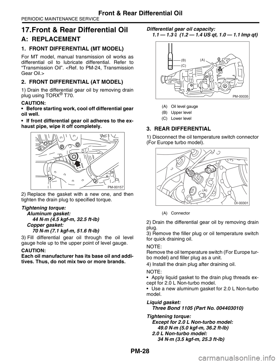
3) Fill differential gear oil through the oil level
gauge hole up to the upper point of level gauge.
CAUTION:
Each oil manufacturer has its base oil and addi-
tives. Thus, do not mix two or more brands.Differential gear oil capacity:
1.1 — 1.32 (1.2 — 1.4 US qt, 1.0 — 1.1 Imp qt)
3. REAR DIFFERENTIAL
1) Disconnect the oil temperature switch connector
(For Europe turbo model).
2) Drain the differential gear oil by removing drain
plug.
3) Remove the filler plug or oil temperature switch
for quick draining oil.
NOTE:
Remove the oil temperature switch (For Europe tur-
bo model) and filler plug as a unit.
4) Install the drain plug after draining oil.
NOTE:
Apply liquid gasket to the drain plug threads ex-
cept for 2.0 L Non-turbo model.
Use a new aluminum gasket for 2.0 L Non-turbo
model.
Liquid gasket:
Three Bond 1105 (Part No. 004403010)
Tightening torque:
Except for 2.0 L Non-turbo model:
49.0 N·m (5.0 kgf-m, 36.2 ft-lb)
2.0 L Non-turbo model:
34 N·m (3.5 kgf-m, 25.3 ft-lb)
PM-00157
(A) Oil level gauge
(B) Upper level
(C) Lower level
(A) Connector
PM-00035
(B)
(C)(A)
DI-00301
(A)
Page 766 of 2870
PM-29
PERIODIC MAINTENANCE SERVICE
Front & Rear Differential Oil
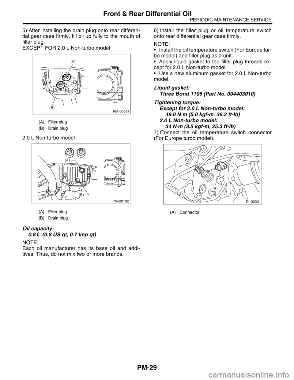
5) After installing the drain plug onto rear differen-
tial gear case firmly, fill oil up fully to the mouth of
filler plug.
EXCEPT FOR 2.0 L Non-turbo model
2.0 L Non-turbo model
Oil capacity:
0.82 (0.8 US qt, 0.7 Imp qt)
NOTE:
Each oil manufacturer has its base oil and addi-
tives. Thus, do not mix two or more brands.6) Install the filler plug or oil temperature switch
onto rear differential gear case firmly.
NOTE:
Install the oil temperature switch (For Europe tur-
bo model) and filler plug as a unit.
Apply liquid gasket to the filler plug threads ex-
cept for 2.0 L Non-turbo model.
Use a new aluminum gasket for 2.0 L Non-turbo
model.
Liquid gasket:
Three Bond 1105 (Part No. 004403010)
Tightening torque:
Except for 2.0 L Non-turbo model:
49.0 N·m (5.0 kgf-m, 36.2 ft-lb)
2.0 L Non-turbo model:
34 N·m (3.5 kgf-m, 25.3 ft-lb)
7) Connect the oil temperature switch connector
(For Europe turbo model).
(A) Filler plug
(B) Drain plug
(A) Filler plug
(B) Drain plug
PM-00037
(A)
(B)
PM-00102
(A)
(B)
(A) Connector
DI-00301
(A)
Page 779 of 2870
PM-42
PERIODIC MAINTENANCE SERVICE
Steering System (Power Steering)
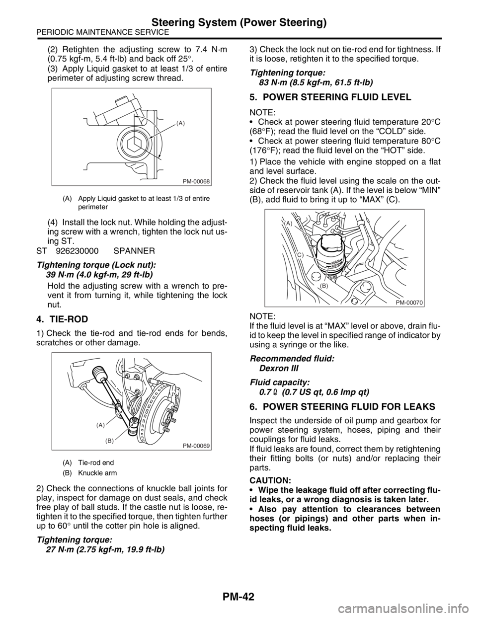
(2) Retighten the adjusting screw to 7.4 N·m
(0.75 kgf-m, 5.4 ft-lb) and back off 25°.
(3) Apply Liquid gasket to at least 1/3 of entire
perimeter of adjusting screw thread.
(4) Install the lock nut. While holding the adjust-
ing screw with a wrench, tighten the lock nut us-
ing ST.
ST 926230000 SPANNER
Tightening torque (Lock nut):
39 N·m (4.0 kgf-m, 29 ft-lb)
Hold the adjusting screw with a wrench to pre-
vent it from turning it, while tightening the lock
nut.
4. TIE-ROD
1) Check the tie-rod and tie-rod ends for bends,
scratches or other damage.
2) Check the connections of knuckle ball joints for
play, inspect for damage on dust seals, and check
free play of ball studs. If the castle nut is loose, re-
tighten it to the specified torque, then tighten further
up to 60° until the cotter pin hole is aligned.
Tightening torque:
27 N·m (2.75 kgf-m, 19.9 ft-lb)3) Check the lock nut on tie-rod end for tightness. If
it is loose, retighten it to the specified torque.
Tightening torque:
83 N·m (8.5 kgf-m, 61.5 ft-lb)
5. POWER STEERING FLUID LEVEL
NOTE:
Check at power steering fluid temperature 20°C
(68°F); read the fluid level on the “COLD” side.
Check at power steering fluid temperature 80°C
(176°F); read the fluid level on the “HOT” side.
1) Place the vehicle with engine stopped on a flat
and level surface.
2) Check the fluid level using the scale on the out-
side of reservoir tank (A). If the level is below “MIN”
(B), add fluid to bring it up to “MAX” (C).
NOTE:
If the fluid level is at “MAX” level or above, drain flu-
id to keep the level in specified range of indicator by
using a syringe or the like.
Recommended fluid:
Dexron III
Fluid capacity:
0.72 (0.7 US qt, 0.6 Imp qt)
6. POWER STEERING FLUID FOR LEAKS
Inspect the underside of oil pump and gearbox for
power steering system, hoses, piping and their
couplings for fluid leaks.
If fluid leaks are found, correct them by retightening
their fitting bolts (or nuts) and/or replacing their
parts.
CAUTION:
Wipe the leakage fluid off after correcting flu-
id leaks, or a wrong diagnosis is taken later.
Also pay attention to clearances between
hoses (or pipings) and other parts when in-
specting fluid leaks.
(A) Apply Liquid gasket to at least 1/3 of entire
perimeter
(A) Tie-rod end
(B) Knuckle arm
PM-00068
(A)
PM-00069
(A)
(B)
PM-00070
(A)
(C)
(B)
Page 799 of 2870
FU(H4SO)-17
FUEL INJECTION (FUEL SYSTEM)
Intake Manifold
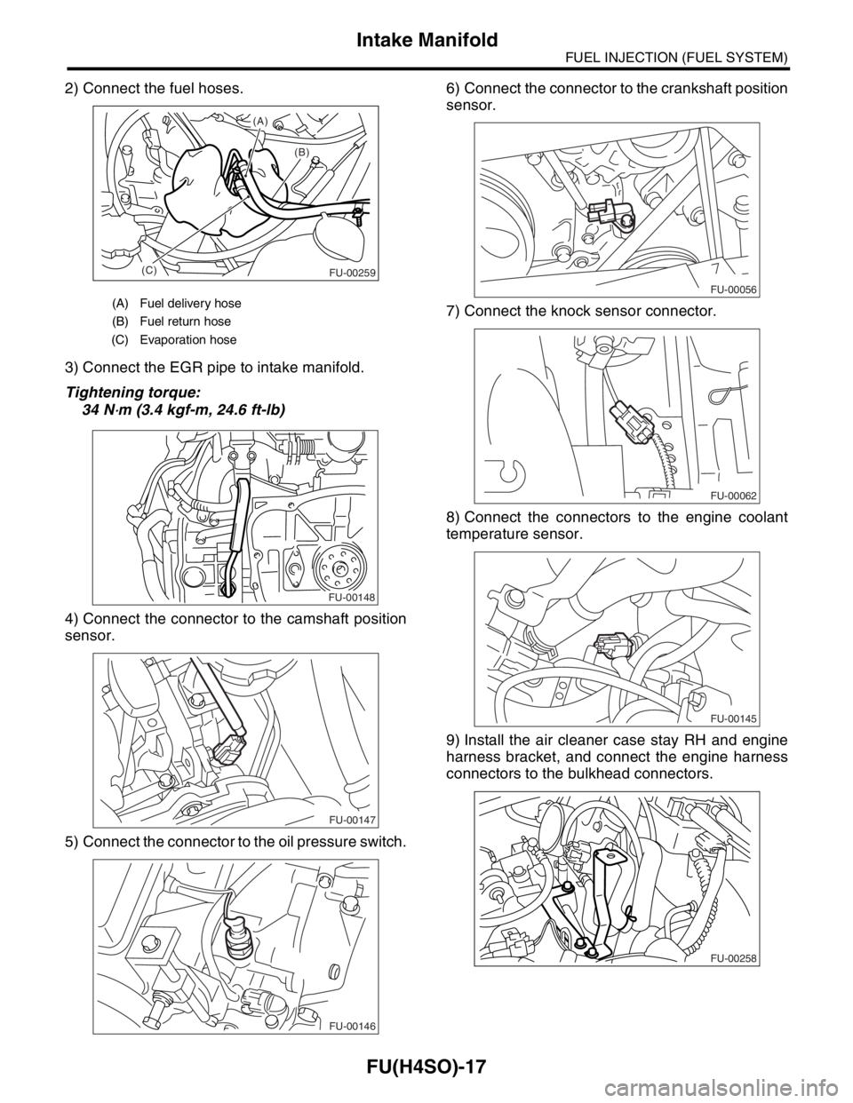
2) Connect the fuel hoses.
3) Connect the EGR pipe to intake manifold.
Tightening torque:
34 N
⋅m (3.4 kgf-m, 24.6 ft-lb)
4) Connect the connector to the camshaft position
sensor.
5) Connect the connector to the oil pressure switch.6) Connect the connector to the crankshaft position
sensor.
7) Connect the knock sensor connector.
8) Connect the connectors to the engine coolant
temperature sensor.
9) Install the air cleaner case stay RH and engine
harness bracket, and connect the engine harness
connectors to the bulkhead connectors.
(A) Fuel delivery hose
(B) Fuel return hose
(C) Evaporation hose
(B) (A)
(C)
FU-00259
FU-00148
FU-00147
FU-00146
FU-00056
FU-00062
FU-00145
FU-00258