2004 SUBARU FORESTER oil temperature
[x] Cancel search: oil temperaturePage 1929 of 2870

EN(H4DOTC)-296
ENGINE (DIAGNOSTIC)
General Diagnostic Table
*1: Check ignition coil & ignitor ASSY and spark plug.
*2: Indicate the symptom occurring only in cold temperatures.
*3: Ensure the secure installation.
*4: Check fuel injector, fuel pressure regulator and fuel filter.
*5: Inspect air leak in air intake system.
*6: Adjust accelerator cable. 6. Surging1) Manifold absolute pressure sensor
2) Mass air flow and intake air temperature sensor
3) Engine coolant temperature sensor (*2)
4) Crankshaft position sensor (*3)
5) Camshaft position sensor (*3)
6) Fuel injection parts (*4)
7) Throttle position sensor
8) Fuel pump and fuel pump relay
7. Spark knock1) Manifold absolute pressure sensor
2) Mass air flow and intake air temperature sensor
3) Engine coolant temperature sensor
4) Knock sensor
5) Fuel injection parts (*4)
6) Fuel pump and fuel pump relay
8. After burning in exhaust system1) Manifold absolute pressure sensor
2) Mass air flow and intake air temperature sensor
3) Engine coolant temperature sensor (*2)
4) Fuel injection parts (*4)
5) Fuel pump and fuel pump relay Symptom Problem parts
Page 1945 of 2870
FU(H4DOTC 2.5)-15
FUEL INJECTION (FUEL SYSTEM)
Intake Manifold
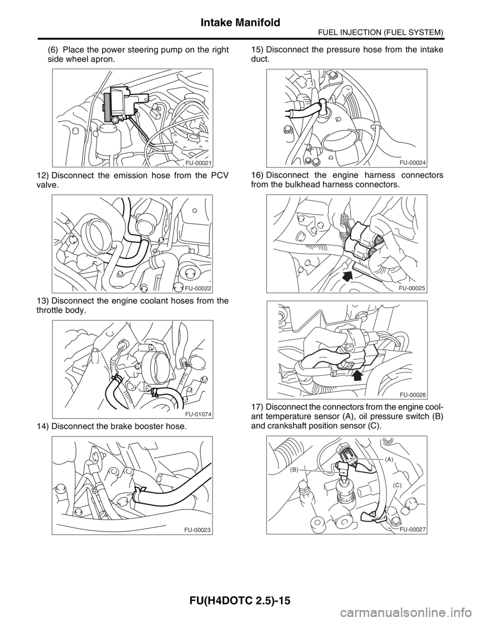
(6) Place the power steering pump on the right
side wheel apron.
12) Disconnect the emission hose from the PCV
valve.
13) Disconnect the engine coolant hoses from the
throttle body.
14) Disconnect the brake booster hose.15) Disconnect the pressure hose from the intake
duct.
16) Disconnect the engine harness connectors
from the bulkhead harness connectors.
17) Disconnect the connectors from the engine cool-
ant temperature sensor (A), oil pressure switch (B)
and crankshaft position sensor (C).
FU-00021
FU-00022
FU-01074
FU-00023
FU-00024
FU-00025
FU-00026
(A)
(B)
(C)
FU-00027
Page 1947 of 2870
FU(H4DOTC 2.5)-17
FUEL INJECTION (FUEL SYSTEM)
Intake Manifold
B: INSTALLATION
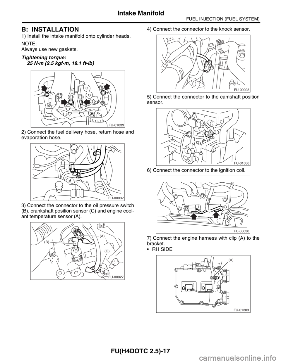
1) Install the intake manifold onto cylinder heads.
NOTE:
Always use new gaskets.
Tightening torque:
25 N·m (2.5 kgf-m, 18.1 ft-lb)
2) Connect the fuel delivery hose, return hose and
evaporation hose.
3) Connect the connector to the oil pressure switch
(B), crankshaft position sensor (C) and engine cool-
ant temperature sensor (A).4) Connect the connector to the knock sensor.
5) Connect the connector to the camshaft position
sensor.
6) Connect the connector to the ignition coil.
7) Connect the engine harness with clip (A) to the
bracket.
RH SIDE
FU-01039
FU-00032
(A)
(B)
(C)
FU-00027
FU-00028
FU-01038
FU-00030
FU-01309 (A)
Page 2283 of 2870

EN(H4DOTC 2.5)-259
ENGINE (DIAGNOSTIC)
General Diagnostic Table
*1: Check ignition coil & ignitor ASSY and spark plug.
*2: Indicate the symptom occurring only in cold temperatures.
*3: Ensure the secure installation.
*4: Check fuel injector, fuel pressure regulator and fuel filter.
*5: Inspect air leak in air intake system. 7. Spark knock1) Manifold absolute pressure sensor
2) Mass air flow and intake air temperature sensor
3) Engine coolant temperature sensor
4) Knock sensor
5) Fuel injection parts (*4)
6) Fuel pump and fuel pump relay
8. After burning in exhaust system1) Manifold absolute pressure sensor
2) Mass air flow and intake air temperature sensor
3) Engine coolant temperature sensor (*2)
4) Fuel injection parts (*4)
5) Fuel pump and fuel pump relay Symptom Problem parts
Page 2313 of 2870

AUTOMATIC TRANSMISSION
4AT
Page
1. General Description ....................................................................................2
2. Automatic Transmission Fluid ...................................................................30
3. Differential Gear Oil...................................................................................31
4. Road Test..................................................................................................32
5. Stall Test ...................................................................................................33
6. Time Lag Test ...........................................................................................35
7. Line Pressure Test ....................................................................................36
8. Transfer Clutch Pressure Test ..................................................................38
9. Automatic Transmission Assembly ...........................................................39
10. Transmission Mounting System ................................................................47
11. Extension Case Oil Seal ...........................................................................49
12. Differential Side Retainer Oil Seal.............................................................50
13. Inhibitor Switch ..........................................................................................51
14. Front Vehicle Speed Sensor .....................................................................55
15. Rear Vehicle Speed Sensor ......................................................................59
16. Torque Converter Turbine Speed Sensor .................................................60
17. Control Valve Body ...................................................................................61
18. Air Bleeding of Control Valve ....................................................................70
19.
Shift Solenoids, Duty Solenoids and ATF Temperature Sensor.........................71
20. Transfer Duty Solenoid and Valve Body ...................................................73
21. ATF Filter ..................................................................................................76
22. Transmission Control Module (TCM) ........................................................77
23. Dropping Resistor .....................................................................................78
24. ATF Cooler Pipe and Hose .......................................................................79
25. ATF Cooler (With Warmer Function).........................................................84
26. Air Breather Hose......................................................................................87
27. Oil Charger Pipe........................................................................................88
28. Torque Converter Clutch Assembly ..........................................................89
29. Extension Case .........................................................................................90
30. Transfer Clutch..........................................................................................92
31. Reduction Driven Gear..............................................................................97
32. Reduction Drive Gear................................................................................99
33. Parking Pawl ...........................................................................................101
34. Torque Converter Clutch Case ...............................................................102
35. Oil Pump Housing ...................................................................................105
36. Drive Pinion Shaft Assembly ...................................................................111
37. Front Differential......................................................................................117
38. AT Main Case .........................................................................................123
39. Transmission Control Device ..................................................................142
Page 2316 of 2870
4AT-4
AUTOMATIC TRANSMISSION
General Description
10.FINAL REDUCTION
Model 2.0 L Turbo Non-turbo, 2.5 L Turbo
Front final reduction gear ratio 4.111 (37/9) 4.444 (40/9)
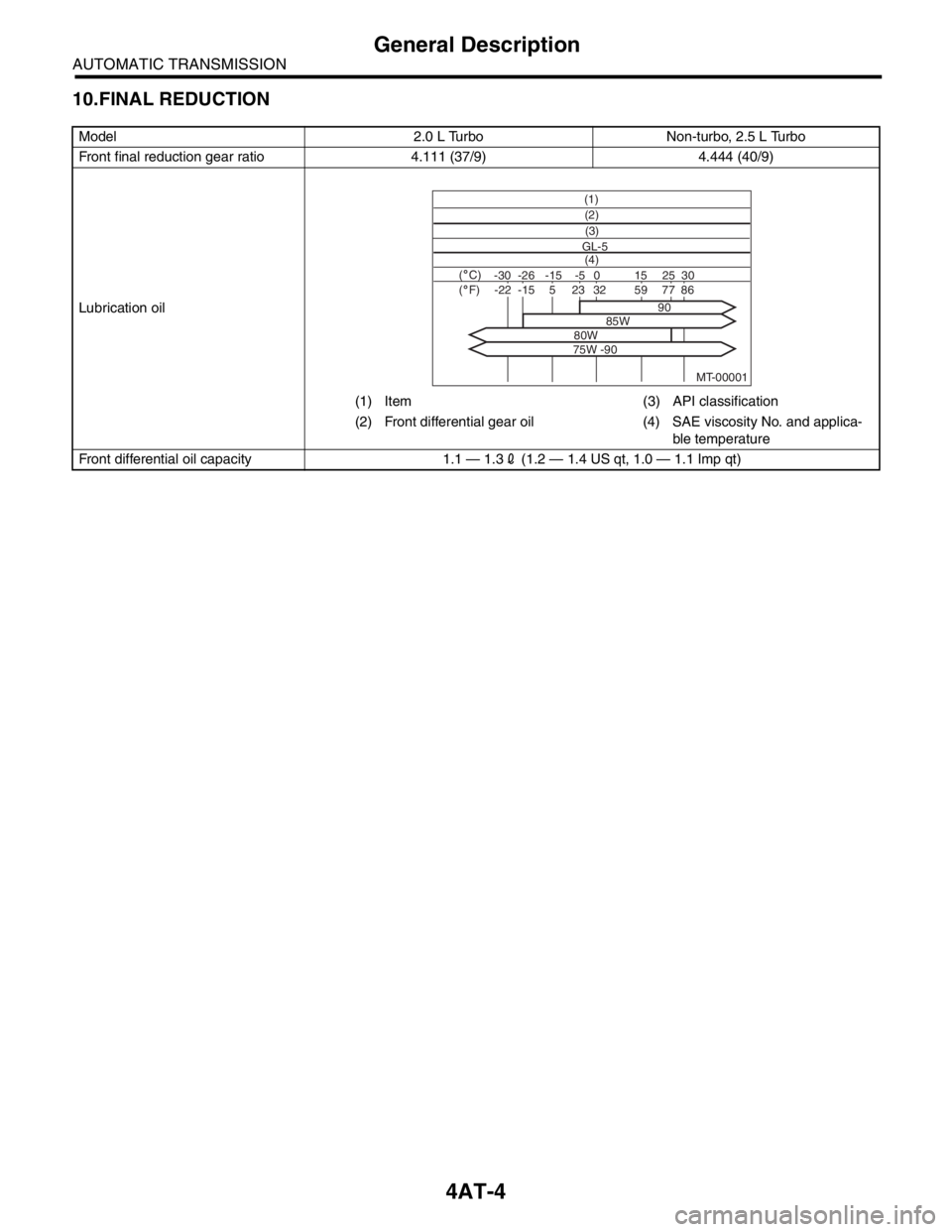
Lubrication oil
(1) Item (3) API classification
(2) Front differential gear oil (4) SAE viscosity No. and applica-
ble temperature
Front differential oil capacity 1.1 — 1.32 (1.2 — 1.4 US qt, 1.0 — 1.1 Imp qt)
MT-00001
(1)
(4) GL-5(3) (2)
( C)( F)-30 -26 -15 15
90
85W
80W
75W -9025 30 -5 0-22-1523328659775
Page 2342 of 2870
4AT-30
AUTOMATIC TRANSMISSION
Automatic Transmission Fluid
2. Automatic Transmission Flu-
id
A: INSPECTION
NOTE:
The level of ATF varies with fluid temperature. Pay
attention to the ATF temperature when checking
ATF level.
1) Raise the ATF temperature by driving a distance
of 5 to 10 km (3 to 6 miles). Otherwise, idle the en-
gine to raise ATF temperature to 70 — 80°C (158
— 176°F) on Subaru Select Monitor.
TION, Subaru Select Monitor.>
2) Make sure the vehicle is level.
3) After selecting all positions (P, R, N, D, 3, 2, 1),
set the select lever in “P” range. Measure the ATF
level with engine idling for one or two minutes.
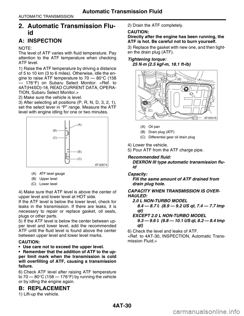
4) Make sure that ATF level is above the center of
upper level and lower level at HOT side.
If the ATF level is below the lower level, check for
leaks in the transmission. If there are leaks, it is
necessary to repair or replace gasket, oil seals,
plugs or other parts.
5) If the ATF level is below the center between up-
per level and lower level, add the recommended
ATF until the fluid level is found above the center
between upper level and lower level marks.
CAUTION:
Use care not to exceed the upper level.
Remember that the addition of ATF to the up-
per limit mark when the transmission is cold
will overfilling of ATF, causing a transmission
failure.
6) Check ATF level after raising ATF temperature
to 70 — 80°C (158 — 176°F) by running the vehicle
or by idling the engine again.
B: REPLACEMENT
1) Lift-up the vehicle.2) Drain the ATF completely.
CAUTION:
Directly after the engine has been running, the
ATF is hot. Be careful not to burn yourself.
3) Replace the gasket with new one, and then tight-
en the drain plug (ATF).
Tightening torque:
25 N
⋅m (2.5 kgf-m, 18.1 ft-lb)
4) Lower the vehicle.
5) Pour ATF from the ATF charge pipe.
Recommended fluid:
DEXRON III type automatic transmission flu-
id
Capacity:
Fill the same amount of ATF drained from
drain plug hole.
CAPACITY WHEN TRANSMISSION IS OVER-
HAULED:
2.0 L NON-TURBO MODEL
8.4 — 8.72 (8.9 — 9.2 US qt, 7.4 — 7.7 Imp
qt)
EXCEPT 2.0 L NON-TURBO MODEL
9.3 — 9.62 (9.8 — 10.1 US qt, 8.2 — 8.4 Imp
qt)
6) Check the level and leaks of ATF.
(A) ATF level gauge
(B) Upper level
(C) Lower level
AT-00674
COLD
LFHOT LF
(C)
(C)
(B)
(B)
(A)(A) Oil pan
(B) Drain plug (ATF)
(C) Differential gear oil drain plug
AT-00016
(A) (B)
(C)
Page 2344 of 2870

4AT-32
AUTOMATIC TRANSMISSION
Road Test
4. Road Test
A: INSPECTION
1. GENERAL PRECAUTION
Road tests should be conducted to properly diag-
nose the condition of the automatic transmission.
NOTE:
When performing the test, do not exceed posted
speed limit.
2. D RANGE SHIFT FUNCTION
Check shifting between 1st ←→ 2nd ←→ 3rd ←→
4th while driving on normal city streets.
3. D RANGE SHIFT SHOCK
Check the shock level when shifting up during nor-
mal driving.
4. KICK-DOWN FUNCTION
Check kick-down for each gear. Also check the
kick-down shock level.
5. ENGINE BRAKE OPERATION
Check the 3rd gear engine brake when shifting
down from D ←→ 3rd range while driving in 4th
gear of D range [50 — 60 km/h (31 — 37 MPH)].
Check the 2nd gear engine brake when shifting
between 3rd ←→ 2nd range while driving in the 3rd
range of 3rd gear [40 — 50 km/h (25 — 31 MPH)].
Check the 1st gear engine brake when shifting
between 2nd ←→ 1st range while driving in the 2nd
range of 2nd gear [20 — 30 km/h (12 — 19 MPH)].
6. LOCK-UP FUNCTION
Check that rpm does not change sharply when
the axle pedal is lightly depressed when driving on
flat roads at 60 km/h (37 MPH).
Check slip lock-up with following procedure.
Subaru Select Monitor is needed for checking (EC,
EK model).
Before start checking, check that the DTC is not ex-
isted using Subaru Select Monitor. When the DTC
is existed, perform the collective action with DTC
and check that the DTC is not existed again, and
then start the checking.
1) The check performed on flat and straight road or
free roller.
NOTE:
Slip lock-up does not operate when the vehicle is
lifted up, because of not occurring surface resis-
tance.
Also checking on the free roller, check with de-
pressing foot brake lightly to make the checking
easier, because the surface resistance will be defi-
cient2) Connect the Subaru Select Monitor.
3) Check ATF temperature using Subaru Select
Monitor.
NOTE:
ATF temperature is between 50 — 100°C (122
— 212°F).
When the temperature is low, warm-up the ATF
by running the vehicle or etc.
4) Start the engine, and make the lock-up duty be
able to read on data display of Subaru Select Mon-
itor.
5) 35 — 40 Drive the vehicle at a constant speed of
35 — 40 km/h (22 — 25 MPH).
6) Read the lock-up duty while vehicle is running.
Standard value:
25 — 45%
NOTE:
On the free roller, the value sometimes lowers.
Slip lock-up control is not operating when the
lock-up duty is less than 5%, or when the lock-up
duty goes down immediately after starts rise. On
these cases, improper ATF or deterioration of ATF
may be the cause. Check the amount of ATF or re-
place them, and then recheck it.
7. P RANGE OPERATION
Stop the vehicle on an uphill grade of 5% or more
and shift to “P” range. Check that the vehicle does
not move when the parking brake is released.
8. NOISE AND VIBRATION
Check for unusual sounds and vibration while driv-
ing and during shifting.
9. CLIMBING CONTROL FUNCTION
Check that the gear remains in 3rd when going
up a grade.
Check that the gear remains in 3rd when apply-
ing the brakes while going down a grade.
10.TRANSFER CLUTCH
Check tight corner braking when the vehicle started
with steering fully turned.
11.OIL LEAKS
After the driving test, inspect for oil leaks.