2004 SUBARU FORESTER air bleeding
[x] Cancel search: air bleedingPage 769 of 2870

PM-32
PERIODIC MAINTENANCE SERVICE
Brake Fluid
19.Brake Fluid
A: REPLACEMENT
1) Lift-up the vehicle.
2) Remove both front and rear wheels.
3) Draw out the brake fluid from master cylinder
with syringe.
4) Refill the reservoir tank with recommended
brake fluid.
Recommended brake fluid:
FMVSS No. 116, fresh DOT3 or DOT4 brake
fluid
CAUTION:
Avoid mixing different brands of brake fluid
to prevent degrading the quality of the fluid.
Be careful not to allow dirt or dust to get into
the reservoir tank.
Bleeding sequence (1) → (2) → (3) → (4)
5) Install one end of a vinyl tube onto the air bleeder
and insert the other end of the tube into a container
to collect the brake fluid.
CAUTION:
Cover the bleeder with waste cloth, when
loosening it, to prevent brake fluid from being
splashed over surrounding parts. During the bleeding operation, keep the
brake reservoir tank filled with brake fluid to
eliminate entry of air.
The brake pedal operating must be very slow.
For convenience and safety, two people
should do the work.
NOTE:
The amount of brake fluid required is approx. 500
m2 (16.9 US fl oz, 17.6 Imp fl oz) for total brake
system.
6) Instruct your co-worker to depress the brake
pedal slowly two or three times and then hold it de-
pressed.
7) Loosen the bleeder screw approx. 1/4 turn until a
small amount of brake fluid drains into container,
and then quickly tighten the screw.
8) Repeat steps 6) and 7) above until there are no
air bubbles in the drained brake fluid and new fluid
flows through vinyl tube.
NOTE:
Add brake fluid as necessary while performing the
air bleed operation, in order to prevent the tank
from running short of brake fluid.
9) After completing the bleeding operation, hold
brake pedal depressed and tighten the bleeder
screw and install bleeder cap.
Tightening torque:
8 N·m (0.8 kgf-m, 5.8 ft-lb)
10) Bleed air from each wheel cylinder by following
the previous 5 steps.
11) Depress the brake pedal with a force of approx.
294 N (30 kgf, 66 lb) and hold it there for approx. 20
seconds. At this time check the pedal to see if it
makes any unusual movement. Visually inspect the
bleeder screws and brake pipe joints to make sure
that there is no fluid leakage.
12) Install the wheels, and drive the vehicle for a
short distance between 2 to 3 km (1 to 2 miles) to
make sure that brakes are operating properly.
(1) Front right
(2) Rear left
(3) Front left
(4) Rear right
(5) Secondary
(6) Primary
(1) (4)
(2) (3) (5) (6)
PM-00047
PM-00048
Page 772 of 2870

PM-35
PERIODIC MAINTENANCE SERVICE
Brake Linings and Drums
2) Check the disk rotor for wear, dents or other
damage. If the inside surface of disk rotor is
streaked, correct the surface with emery cloth
(#200 or more). If it is unevenly worn or tapered,
correct or replace it.
Brake drum inside diameter
Standard value: 170 mm (6.69 in)
Wear limit: 171 mm (6.73 in)
3) If the deformation or wear of back plate, shoe,
etc. is noticeable, replace them.
4) When the shoe return spring tension is exces-
sively weakened, replace it.B: ADJUSTMENT
1. REAR DRUM BRAKE
The main brake is adjusted automatically, and so
there is no need to adjust it.
2. PARKING BRAKE (REAR DISC BRAKE)
For rear disc brake, adjust the parking brake after
bleeding air.
1) Remove the rear cover (rubber) installed at back
plate.
2) Turn the adjuster toward arrow mark (upward)
until it is locked slightly, by using a flat tip screwdriv-
er as shown in illustration.
3) Turn back (downward) the adjuster 3 to 4 notch-
es.
4) Install the rear cover (rubber) at original position
correctly.
(A) Inside diameter
(B) Disk
PM-00055
(A) (B)
(A) Adjuster
(B) Rear cover (rubber)
(C) Back plate
PM-00056
(B)
(C) (A)
Page 2313 of 2870

AUTOMATIC TRANSMISSION
4AT
Page
1. General Description ....................................................................................2
2. Automatic Transmission Fluid ...................................................................30
3. Differential Gear Oil...................................................................................31
4. Road Test..................................................................................................32
5. Stall Test ...................................................................................................33
6. Time Lag Test ...........................................................................................35
7. Line Pressure Test ....................................................................................36
8. Transfer Clutch Pressure Test ..................................................................38
9. Automatic Transmission Assembly ...........................................................39
10. Transmission Mounting System ................................................................47
11. Extension Case Oil Seal ...........................................................................49
12. Differential Side Retainer Oil Seal.............................................................50
13. Inhibitor Switch ..........................................................................................51
14. Front Vehicle Speed Sensor .....................................................................55
15. Rear Vehicle Speed Sensor ......................................................................59
16. Torque Converter Turbine Speed Sensor .................................................60
17. Control Valve Body ...................................................................................61
18. Air Bleeding of Control Valve ....................................................................70
19.
Shift Solenoids, Duty Solenoids and ATF Temperature Sensor.........................71
20. Transfer Duty Solenoid and Valve Body ...................................................73
21. ATF Filter ..................................................................................................76
22. Transmission Control Module (TCM) ........................................................77
23. Dropping Resistor .....................................................................................78
24. ATF Cooler Pipe and Hose .......................................................................79
25. ATF Cooler (With Warmer Function).........................................................84
26. Air Breather Hose......................................................................................87
27. Oil Charger Pipe........................................................................................88
28. Torque Converter Clutch Assembly ..........................................................89
29. Extension Case .........................................................................................90
30. Transfer Clutch..........................................................................................92
31. Reduction Driven Gear..............................................................................97
32. Reduction Drive Gear................................................................................99
33. Parking Pawl ...........................................................................................101
34. Torque Converter Clutch Case ...............................................................102
35. Oil Pump Housing ...................................................................................105
36. Drive Pinion Shaft Assembly ...................................................................111
37. Front Differential......................................................................................117
38. AT Main Case .........................................................................................123
39. Transmission Control Device ..................................................................142
Page 2378 of 2870

4AT-65
AUTOMATIC TRANSMISSION
Control Valve Body
6) Fill liquid gasket to holes except for bolt holes
(three) of transmission case.
Liquid gasket:
THREE BOND 1217B (Part No. K0877YA020)
7) Install the oil pan with equally tighten the bolts.
Tightening torque:
5 N
⋅m (0.5 kgf-m, 3.6 ft-lb)
8) Pour ATF from the ATF charge pipe.
Recommended fluid:
DEXRON III type automatic transmission flu-
id
Capacity:
Pour fluid as same amount as drained fluid
from drain plug hole.
9) Bleed the air of control valve.
10) Check the ATF level.
11) Execute the learning control promotion.
ING CONTROL, OPERATION, Subaru Select
Monitor.>
C: DISASSEMBLY
Non-turbo model only
1) Remove the oil strainer from lower control valve
body.
NOTE:
While assembling, safekeeping the bolt to identify
bolt position, because the bolt length is different.
2) Remove the duty solenoids, solenoids and sen-
sor from lower control valve body.
NOTE:
While assembling, safekeeping the bolt to identify
bolt position, because the bolt length is different.
AT-01339
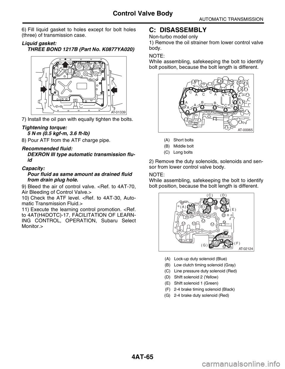
(A) Short bolts
(B) Middle bolt
(C) Long bolts
(A) Lock-up duty solenoid (Blue)
(B) Low clutch timing solenoid (Gray)
(C) Line pressure duty solenoid (Red)
(D) Shift solenoid 2 (Yellow)
(E) Shift solenoid 1 (Green)
(F) 2-4 brake timing solenoid (Black)
(G) 2-4 brake duty solenoid (Red)
AT-00065
A
ABAA
AC
ACC
AB
AC
CC
AT-02124
(E)
(F)(G)
(D)(C)
(B)(A)
Page 2383 of 2870

4AT-70
AUTOMATIC TRANSMISSION
Air Bleeding of Control Valve
18.Air Bleeding of Control Valve
A: PROCEDURE
1) Lift-up the vehicle with shifting the select lever to
“P” range and applying the parking brake.
2) Connect the Subaru Select Monitor to the vehi-
cle.
3) Make sure there is no trouble code using Subaru
Select Monitor.
4) Using Subaru Select Monitor, check that the
ATF temperature is in less than 60°C (140°F).
5) Power OFF the Subaru Select Monitor.
6) Turn the ignition switch to “OFF”.
7) Shift the select lever to “R” range.
8) Depress the brake pedal fully until the air bleed-
ing is completed.
9) Turn the ignition switch to ON.
10) Shift the select lever to “P” range, and then wait
for more than 3 seconds.
11) Shift the select lever to “R” range, and then wait
for more than 3 seconds.
12) Shift the select lever to “N” range, and then wait
for more than 3 seconds.
13) Shift the select lever to “D” range, and then wait
for more than 3 seconds.
14) Shift the select lever to “N” range, and then wait
for more than 3 seconds.
15) Slightly depress the accelerator pedal fully.
16) Slightly release the accelerator pedal fully.
17) Start the engine.
18) Shift the select lever to “D” range.
19) Turn the Subaru Select Monitor switch to ON.
20) Select {Each System Check} in «Main Menu»
of Subaru Select Monitor.
21) On the «System Selection Menu» display
screen, select the “Transmission”. Air bleeding of
control valve starts on transmission. At this time,
the POWER indicator light in combination meter
blinks at 2 Hz. When the POWER indicator light
does not blink, repeat the procedures from step 4).
22) Air bleeding of control valve is finished when
blinking of POWER indicator light in combination
meter changes from 2 Hz to 0.5 Hz.
NOTE:
When blinking of POWER indicator light changes
from 2 Hz to 4 Hz during air bleeding, repeat the
procedure from step 4).
23) Shift the select lever to “N” range, and then turn
the ignition switch to OFF.
24) Shift the select lever to the “P” range, and then
finish the air bleeding.
Page 2827 of 2870

CLUTCH SYSTEM
CL
Page
1. General Description ....................................................................................2
2. Clutch Disc and Cover ..............................................................................16
3. Flywheel ....................................................................................................19
4. Release Bearing and Lever.......................................................................20
5. Operating Cylinder ....................................................................................24
6. Master Cylinder .........................................................................................26
7. Clutch Pipe and Hose ...............................................................................29
8. Clutch Fluid ...............................................................................................31
9. Clutch Fluid Air Bleeding ...........................................................................32
10. Clutch Pedal ..............................................................................................34
11. Clutch Switch ............................................................................................41
12. General Diagnostic Table..........................................................................42
Page 2851 of 2870

CL-25
CLUTCH SYSTEM
Operating Cylinder
B: INSTALLATION
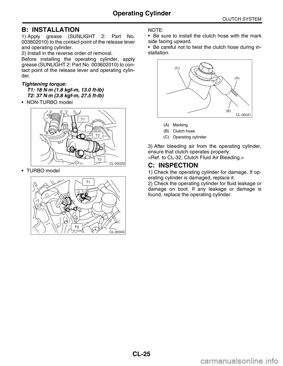
1) Apply grease (SUNLIGHT 2: Part No.
003602010) to the contact point of the release lever
and operating cylinder.
2) Install in the reverse order of removal.
Before installing the operating cylinder, apply
grease (SUNLIGHT 2: Part No. 003602010) to con-
tact point of the release lever and operating cylin-
der.
Tightening torque:
T1: 18 N
⋅m (1.8 kgf-m, 13.0 ft-lb)
T2: 37 N
⋅m (3.8 kgf-m, 27.5 ft-lb)
NON-TURBO model
TURBO modelNOTE:
Be sure to install the clutch hose with the mark
side facing upward.
Be careful not to twist the clutch hose during in-
stallation.
3) After bleeding air from the operating cylinder,
ensure that clutch operates properly.
C: INSPECTION
1) Check the operating cylinder for damage. If op-
erating cylinder is damaged, replace it.
2) Check the operating cylinder for fluid leakage or
damage on boot. If any leakage or damage is
found, replace the operating cylinder.
T2
CL-00039T2
T1
CL-00040
T2
T1
(A) Marking
(B) Clutch hose
(C) Operating cylinder
CL-00041
(A)
(B) (C)
Page 2852 of 2870

CL-26
CLUTCH SYSTEM
Master Cylinder
6. Master Cylinder
A: REMOVAL
1) Thoroughly drain the brake fluid from reservoir
tank.
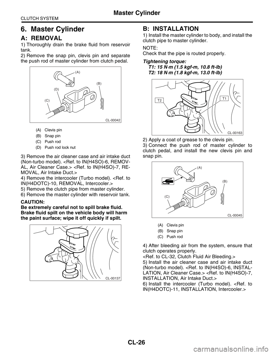
2) Remove the snap pin, clevis pin and separate
the push rod of master cylinder from clutch pedal.
3) Remove the air cleaner case and air intake duct
(Non-turbo model).
4) Remove the intercooler (Turbo model).
5) Remove the clutch pipe from master cylinder.
6) Remove the master cylinder with reservoir tank.
CAUTION:
Be extremely careful not to spill brake fluid.
Brake fluid spilt on the vehicle body will harm
the paint surface; wipe it off quickly if spilt.
B: INSTALLATION
1) Install the master cylinder to body, and install the
clutch pipe to master cylinder.
NOTE:
Check that the pipe is routed properly.
Tightening torque:
T1: 15 N
⋅m (1.5 kgf-m, 10.8 ft-lb)
T2: 18 N
⋅m (1.8 kgf-m, 13.0 ft-lb)
2) Apply a coat of grease to the clevis pin.
3) Connect the push rod of master cylinder to
clutch pedal, and install the new clevis pin and
snap pin.
4) After bleeding air from the system, ensure that
clutch operates properly.
5) Install the air cleaner case and air intake duct
(Non-turbo model).
6) Install the intercooler (Turbo model).
(A) Clevis pin
(B) Snap pin
(C) Push rod
(D) Push rod lock nut
CL-00042
(A)
(B)
(C)(D)
CL-00137
(A) Clevis pin
(B) Snap pin
(C) Push rod
CL-00163
T2T1
CL-00045
(A)
(B)
(C)