2004 SUBARU FORESTER wheel
[x] Cancel search: wheelPage 104 of 2870

AB-4
AIRBAG SYSTEM
General Description
Do not drop the airbag modulator parts, subject
them to high temperature over 93°C (199°F), or let
water, oil, or grease get on them; otherwise, the in-
ternal parts may be damaged and reliability greatly
lowered.
If any damage, opening, or rust is found on the
airbag system wire harness, do not attempt to re-
pair using soldering equipment. Be sure to replace
the faulty harness with a new genuine part.
Install the wire harness securely with the speci-
fied clips to avoid interference or tangled up with
other parts. Do not allow water or oil to come in contact with
the connector terminals. Do not touch the connec-
tor terminals.
Either of the airbag modules for driver, passen-
ger or side, or pretensioner must not be disassem-
bled.
The removed front seat with the airbag module
must be kept at least 200 mm (8 in) away from walls
and other objects.
Do not use the airbag or pretensioner parts from
other vehicles. Always replace defective parts with
new ones.
Never reuse a deployed airbag or pretensioner.
When painting or performing sheet metal work
on the front part of the vehicle, including the front
wheel apron, front fender, and front side frame, re-
move the front sub sensors and wire harness of the
airbag system.
AB-00123
AB-00124
AB-00125
(1) More than 200 mm (8 in)
AB-00126
AB-00779
AB-00128
(1)
Page 112 of 2870

AB-12
AIRBAG SYSTEM
Inspection Locations After a Collision
3. Inspection Locations After a
Collision
A: REPLACEMENT
When airbag system is deployed, replace the fol-
lowing parts.
1. FRONT COLLISION
1) Driver’s airbag module
2) Passenger’s airbag module
3) Driver’s seat belt (pretensioner, lap seat belt pre-
tensioner)
4) Passenger’s seat belt (pretensioner)
5) Airbag control module
6) Front sub-sensor
7) Roll connector
2. SIDE COLLISION
1) Airbag control module
2) Side airbag module (operating side seat bag)
3) Side airbag sensor (operating side)
3. INSPECTION OF OTHER PARTS
Check for the following parts, replace the damaged
parts with new ones.
1) Steering wheel and steering shaft
Check the steering wheel and steering shaft for
mounting condition and deflection of axial and radi-
al direction. Check the steering shaft for deflection
of axial direction with tilt lever released. (After a col-
lision, absorbing part of steering shaft may inflate.)
2) Check the direct type connector of driver’s air-
bag module, pretensioner, etc. for damage, and
also check each harness for pinch and connector
damage. If damage is found, replace the harness
as a unit.
B: INSPECTION
If the vehicle is involved in a collision on any side,
even if it is a slight collision, be sure to check the
following system parts.
1. DRIVER’S AIRBAG MODULE
1) Check for the following, and replace damaged
parts with new ones.
Airbag module is cracked or deformed.
Harness and/or connector is cracked, deformed
or open. Lead wire is exposed.
The module surface is fouled with grease, oil,
water or cleaning solvent.
2) When installing a new driver’s airbag module,
check the following. If necessary, install a new air-
bag module and steering wheel.
The steering wheel is in the way, making it diffi-
cult to install the airbag module. The clearance between the driver’s airbag mod-
ule and steering wheel is not constant.
The steering wheel deformation in axial and radi-
al directions exceed limits.
Specifications:
Height deflection A
Less than 6 mm (0.24 in)
O.D. deflection L
Less than 17 mm (0.67 in)
2. PASSENGER’S AIRBAG MODULE
Check for the following, and replace damaged
parts with new ones.
Airbag module is cracked or deformed.
Harness and/or connector is cracked, deformed
or open. Lead wire is exposed.
Mounting bracket is cracked or deformed.
3. SIDE AIRBAG MODULE
Check for the following, and replace damaged
parts with new ones.
Front seat is damaged or deformed.
Harness and/or connector is cracked, deformed
or open.
Lead wire is exposed.
4. AIRBAG CONTROL MODULE
Check for the following, and replace damaged
parts with new ones.
Control module is cracked or deformed.
Mounting bracket is cracked or deformed.
Connector is scratched or deformed.
Airbag is deployed.
Side airbag is deployed.
AB-00028
L
A
Page 114 of 2870
AB-14
AIRBAG SYSTEM
Driver’s Airbag Module
4. Driver’s Airbag Module
A: REMOVAL
CAUTION:
Refer to “CAUTION” in General Description be-
fore handing the airbag module.
1) Position the front wheels straight ahead. (After
moving the vehicle more than 5 m (16 ft) with front
wheels positioned straight ahead, make sure that
the vehicle moves straight ahead).
2) Turn the ignition switch to OFF.
3) Disconnect the ground cable from battery, and
wait for at least 20 seconds before starting work.
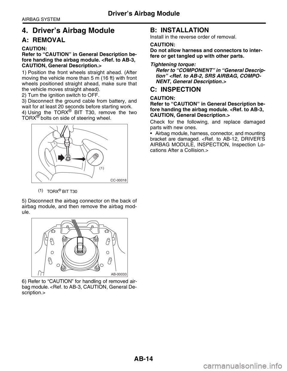
4) Using the TORX
® BIT T30, remove the two
TORX® bolts on side of steering wheel.
5) Disconnect the airbag connector on the back of
airbag module, and then remove the airbag mod-
ule.
6) Refer to “CAUTION” for handling of removed air-
bag module.
B: INSTALLATION
Install in the reverse order of removal.
CAUTION:
Do not allow harness and connectors to inter-
fere or get tangled up with other parts.
Tightening torque:
Refer to “COMPONENT” in “General Descrip-
tion”
C: INSPECTION
CAUTION:
Refer to “CAUTION” in General Description be-
fore handing the airbag module.
Check for the following, and replace damaged
parts with new ones.
Airbag module, harness, connector, and mounting
bracket are damaged.
cations After a Collision.>
(1)
TORX® BIT T30
CC-00018
(1)
AB-00033
Page 120 of 2870
AB-20
AIRBAG SYSTEM
Roll Connector
9. Roll Connector
A: REMOVAL
1) Turn the ignition switch to OFF.
2) Disconnect the ground cable from battery, and
wait for at least 20 seconds before starting work.
3) Remove the driver’s airbag module.
4) Remove the steering wheel.
5) Remove the steering column cover.
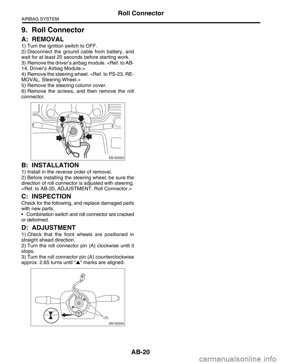
6) Remove the screws, and then remove the roll
connector.
B: INSTALLATION
1) Install in the reverse order of removal.
2) Before installing the steering wheel, be sure the
direction of roll connector is adjusted with steering.
C: INSPECTION
Check for the following, and replace damaged parts
with new parts.
Combination switch and roll connector are cracked
or deformed.
D: ADJUSTMENT
1) Check that the front wheels are positioned in
straight ahead direction.
2) Turn the roll connector pin (A) clockwise until it
stops.
3) Turn the roll connector pin (A) counterclockwise
approx. 2.65 turns until “▲” marks are aligned.
AB-00593
AB-00594
(A)
Page 127 of 2870
AB-27
AIRBAG SYSTEM
Disposal of Airbag Module (Deploying After Removal from Vehicle)
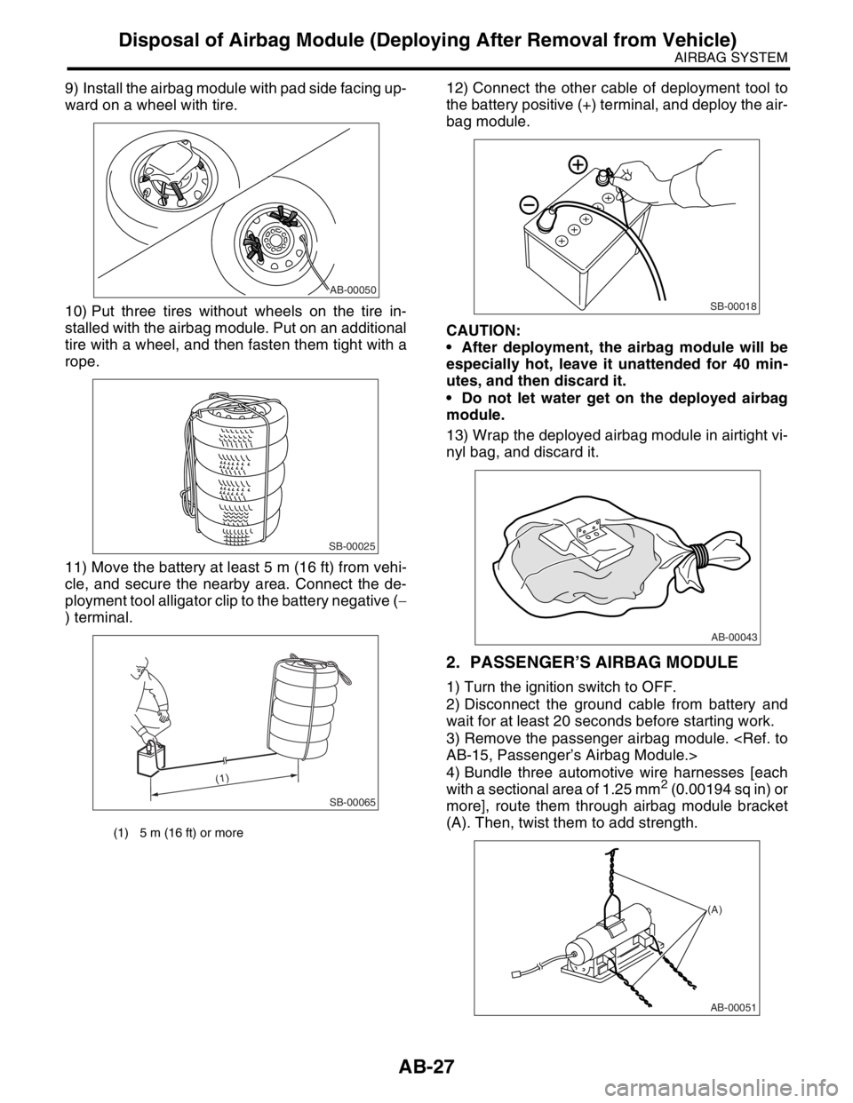
9) Install the airbag module with pad side facing up-
ward on a wheel with tire.
10) Put three tires without wheels on the tire in-
stalled with the airbag module. Put on an additional
tire with a wheel, and then fasten them tight with a
rope.
11) Move the battery at least 5 m (16 ft) from vehi-
cle, and secure the nearby area. Connect the de-
ployment tool alligator clip to the battery negative (−
) terminal.12) Connect the other cable of deployment tool to
the battery positive (+) terminal, and deploy the air-
bag module.
CAUTION:
After deployment, the airbag module will be
especially hot, leave it unattended for 40 min-
utes, and then discard it.
Do not let water get on the deployed airbag
module.
13) Wrap the deployed airbag module in airtight vi-
nyl bag, and discard it.
2. PASSENGER’S AIRBAG MODULE
1) Turn the ignition switch to OFF.
2) Disconnect the ground cable from battery and
wait for at least 20 seconds before starting work.
3) Remove the passenger airbag module.
4) Bundle three automotive wire harnesses [each
with a sectional area of 1.25 mm
2 (0.00194 sq in) or
more], route them through airbag module bracket
(A). Then, twist them to add strength.
(1) 5 m (16 ft) or more
AB-00050
SB-00025
SB-00065
(1)
SB-00018
AB-00043
AB-00051
(A)
Page 128 of 2870
AB-28
AIRBAG SYSTEM
Disposal of Airbag Module (Deploying After Removal from Vehicle)
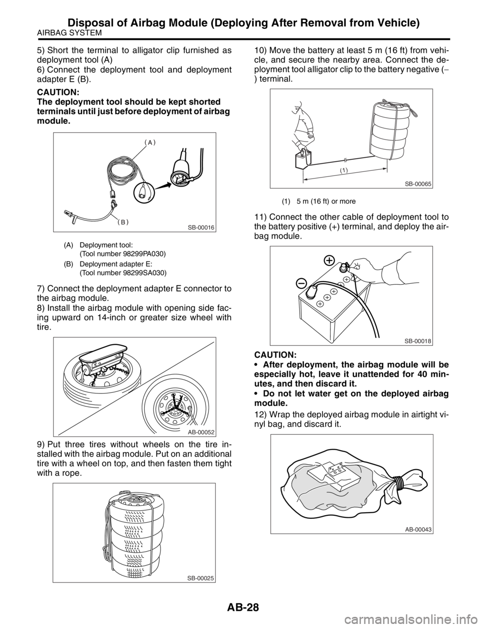
5) Short the terminal to alligator clip furnished as
deployment tool (A)
6) Connect the deployment tool and deployment
adapter E (B).
CAUTION:
The deployment tool should be kept shorted
terminals until just before deployment of airbag
module.
7) Connect the deployment adapter E connector to
the airbag module.
8) Install the airbag module with opening side fac-
ing upward on 14-inch or greater size wheel with
tire.
9) Put three tires without wheels on the tire in-
stalled with the airbag module. Put on an additional
tire with a wheel on top, and then fasten them tight
with a rope.10) Move the battery at least 5 m (16 ft) from vehi-
cle, and secure the nearby area. Connect the de-
ployment tool alligator clip to the battery negative (−
) terminal.
11) Connect the other cable of deployment tool to
the battery positive (+) terminal, and deploy the air-
bag module.
CAUTION:
After deployment, the airbag module will be
especially hot, leave it unattended for 40 min-
utes, and then discard it.
Do not let water get on the deployed airbag
module.
12) Wrap the deployed airbag module in airtight vi-
nyl bag, and discard it.
(A) Deployment tool:
(Tool number 98299PA030)
(B) Deployment adapter E:
(Tool number 98299SA030)
SB-00016
AB-00052
SB-00025
(1) 5 m (16 ft) or more
SB-00065
(1)
SB-00018
AB-00043
Page 129 of 2870
AB-29
AIRBAG SYSTEM
Disposal of Airbag Module (Deploying After Removal from Vehicle)
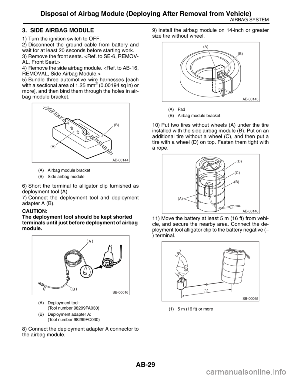
3. SIDE AIRBAG MODULE
1) Turn the ignition switch to OFF.
2) Disconnect the ground cable from battery and
wait for at least 20 seconds before starting work.
3) Remove the front seats.
4) Remove the side airbag module.
5) Bundle three automotive wire harnesses [each
with a sectional area of 1.25 mm
2 (0.00194 sq in) or
more], and then bind them through the holes in air-
bag module bracket.
6) Short the terminal to alligator clip furnished as
deployment tool (A)
7) Connect the deployment tool and deployment
adapter A (B).
CAUTION:
The deployment tool should be kept shorted
terminals until just before deployment of airbag
module.
8) Connect the deployment adapter A connector to
the airbag module.9) Install the airbag module on 14-inch or greater
size tire without wheel.
10) Put two tires without wheels (A) under the tire
installed with the side airbag module (B). Put on an
additional tire without a wheel (C), and then put a
tire with a wheel (D) on top. Fasten them tight with
a rope.
11) Move the battery at least 5 m (16 ft) from vehi-
cle, and secure the nearby area. Connect the de-
ployment tool alligator clip to the battery negative (−
) terminal.
(A) Airbag module bracket
(B) Side airbag module
(A) Deployment tool:
(Tool number 98299PA030)
(B) Deployment adapter A:
(Tool number 98299FC030)
AB-00144
(A)(B)
SB-00016
(A) Pad
(B) Airbag module bracket
(1) 5 m (16 ft) or more
AB-00145
(A)
(B)
AB-00146
(A)
(B)
(C)
(D)
SB-00065
(1)
Page 135 of 2870

AB-3
AIRBAG SYSTEM (DIAGNOSTIC)
Check List for Interview
2. Check List for Interview
A: CHECK
Customer’s Name Inspector’s Name
Date Vehicle Brought In / / Registration No.
Odometer Readingkm
milesVIN
Date Problem Occurred / / Registration Year / /
Weather❏ Fine ❏ Cloudy ❏ Rainy ❏ Snowy ❏ Other:
Temperature°C (°F)
Road Condition❏ Level road❏ Uphill ❏ Downhill❏ Rough road ❏ Others:
Vehicle Operation❏ Starting❏ Idling
❏ Driving (❏ Constant speed❏ Acceleration❏ Deceleration
❏ Steering wheel turn❏ Others: )
Details of Problem
Check Airbag Warning Light❏ Normal (After turning the ignition switch to ON, lit for 7 seconds and goes off.)
❏ Remains ON❏ Remains OFF
Check DTC❏ Normal Code❏ DTC: (Code: )