2004 SUBARU FORESTER wheel
[x] Cancel search: wheelPage 138 of 2870

AB-6
AIRBAG SYSTEM (DIAGNOSTIC)
General Description
The removed front seat with the airbag module
must be kept at least 200 mm (8 in) away from walls
and other objects.
When painting or performing sheet metal work
on the front part of the vehicle, including the front
wheel apron, front fender, and front side frame, re-
move the front sub sensors and wire harness of the
airbag system.
When painting or performing sheet metal work
on the side of the vehicle, including the side sill,
center pillar, and front and rear doors, remove the
side airbag sensors and wiring harness of the air-
bag system.
Do not discard undeployed airbag modules.
They could easily cause a serious accident if acci-
dentally deployed.
(1) More than 200 mm (8 in)
AB-00128
(1)
AB-00129
Page 243 of 2870

SB-9
SEAT BELT SYSTEM
Seat Belt Warning System
14 CHECK HARNESS BETWEEN TCU AND
SEAT BELT TIMER MODULE.
Measure the resistance between seat belt
timer module harness connector and chassis
ground.
Connector & terminal
(B44) No. 7 — Chassis ground:Is the resistance less than 10
Ω?Go to step 15.Repair the short of
harness.
15 CHECK SEAT BELT TIMER MODULE OUT-
PUT SIGNAL.
1) Turn the ignition switch to ON.
2) Measure the voltage between seat belt
timer module harness connector and chassis
ground.
Connector & terminal
(B44) No. 2 (+) — Chassis ground (–):Is the voltage more than 10 V? Go to step 16.Check the wiring
harness and com-
bination meter,
and then repair or
replace them.
16 CHECK POOR CONTACT.
Check the poor contact of seat belt warning
light circuit.Is there any poor contact
occurs?Repair the poor
contact.Go to step 17.
17 CHECK SEAT BELT TIMER MODULE.
1) Connect all connectors.
2) Lift-up the vehicle and place rigid racks.
NOTE:
Raise all wheels off floor.
3) Hold the tang plate disconnected from seat
belt buckle.
4) Start the engine, and set the vehicle speed
less than 19 km/h (12 MPH)
N
OTE:
The speed difference between front and rear
wheels may light the ABS warning light, but this
indicates no malfunction. When diagnosis is fin-
ished, perform the ABS memory clearance pro-
cedure of OBD system.
Check seat belt warning light comes on.Does the seat belt warning
light come on?Go to step 18.Replace the seat
belt timer module.
18 CHECK SEAT BELT TIMER MODULE.
1) Connect all connectors.
2) Lift-up the vehicle and place rigid racks.
N
OTE:
Raise all wheels off floor.
3) Hold the tang plate disconnected from seat
belt buckle.
4) Start the engine, and set the vehicle speed
more than 25 km/h (16 MPH).
NOTE:
The speed difference between front and rear
wheels may light the ABS warning light, but this
indicates no malfunction. When diagnosis is fin-
ished, perform the ABS memory clearance pro-
cedure of OBD system.
Check seat belt warning light comes on and
buzzer beeps.Does the seat belt warning
light come on and buzzer
beep?Temporary poor
contact of connec-
tor or harness may
be the cause.
Check the poor
contact.Replace the seat
belt timer module. Step Check Yes No
Page 250 of 2870

SB-16
SEAT BELT SYSTEM
Disposal of Pretensioner
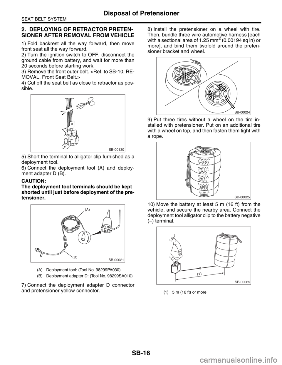
2. DEPLOYING OF RETRACTOR PRETEN-
SIONER AFTER REMOVAL FROM VEHICLE
1) Fold backrest all the way forward, then move
front seat all the way forward.
2) Turn the ignition switch to OFF, disconnect the
ground cable from battery, and wait for more than
20 seconds before starting work.
3) Remove the front outer belt.
4) Cut off the seat belt as close to retractor as pos-
sible.
5) Short the terminal to alligator clip furnished as a
deployment tool.
6) Connect the deployment tool (A) and deploy-
ment adapter D (B).
CAUTION:
The deployment tool terminals should be kept
shorted until just before deployment of the pre-
tensioner.
7) Connect the deployment adapter D connector
and pretensioner yellow connector.8) Install the pretensioner on a wheel with tire.
Then, bundle three wire automotive harness [each
with a sectional area of 1.25 mm
2 (0.00194 sq in) or
more], and bind them twofold around the preten-
sioner bracket and wheel.
9) Put three tires without a wheel on the tire in-
stalled with pretensioner. Put on an additional tire
with a wheel on top, and then fasten them tight with
a rope.
10) Move the battery at least 5 m (16 ft) from the
vehicle, and secure the nearby area. Connect the
deployment tool alligator clip to the battery negative
(−) terminal.
(A) Deployment tool: (Tool No. 98299PA030)
(B) Deployment adapter D: (Tool No. 98299SA010)
SB-00130
SB-00021
(A)
(B)
(1) 5 m (16 ft) or more
SB-00024
SB-00025
SB-00065
(1)
Page 251 of 2870

SB-17
SEAT BELT SYSTEM
Disposal of Pretensioner
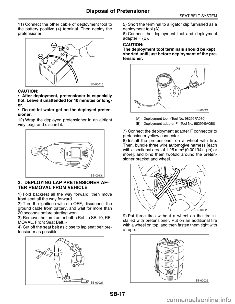
11) Connect the other cable of deployment tool to
the battery positive (+) terminal. Then deploy the
pretensioner.
CAUTION:
After deployment, pretensioner is especially
hot. Leave it unattended for 40 minutes or long-
er.
Do not let water get on the deployed preten-
sioner.
12) Wrap the deployed pretensioner in an airtight
vinyl bag, and discard it.
3. DEPLOYING LAP PRETENSIONER AF-
TER REMOVAL FROM VEHICLE
1) Fold backrest all the way forward, then move
front seat all the way forward.
2) Turn the ignition switch to OFF, disconnect the
ground cable from battery, and wait for more than
20 seconds before starting work.
3) Remove the fornt outer belt.
4) Cut off the seat belt as close to lap seat belt pre-
tensioner as possible.5) Short the terminal to alligator clip furnished as a
deployment tool (A).
6) Connect the deployment tool and deployment
adapter F (B).
CAUTION:
The deployment tool terminals should be kept
shorted until just before deployment of the pre-
tensioner.
7) Connect the deployment adapter F connector to
pretensioner yellow connector.
8) Install the pretensioner on a wheel with tire.
Then, bundle three wire automotive harness [each
with a sectional area of 1.25 mm
2 (0.00194 sq in) or
more], and bind them twofold around the preten-
sioner bracket and wheel.
9) Put three tires without a wheel on the tire in-
stalled with pretensioner. Put on an additional tire
with a wheel on top, and then fasten them tight with
a rope.
SB-00018
SB-00131
SB-00027
(A) Deployment tool: (Tool No. 98299PA030)
(B) Deployment adapter F: (Tool No. 98299SA050)
SB-00021
(A)
(B)
SB-00028
SB-00025
Page 327 of 2870

COM-5
COMMUNICATION SYSTEM
Horn Switch
4. Horn Switch
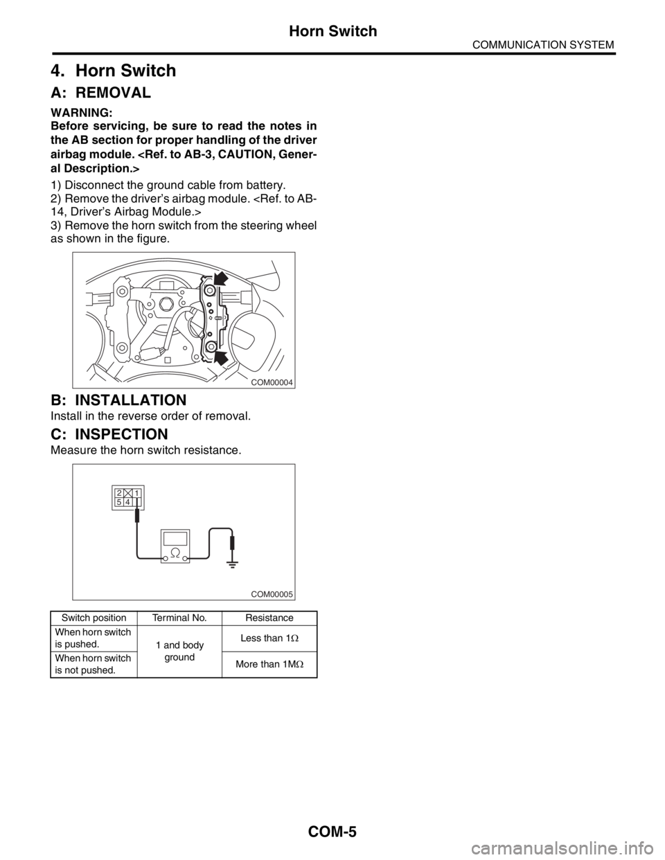
A: REMOVAL
WARNING:
Before servicing, be sure to read the notes in
the AB section for proper handling of the driver
airbag module.
1) Disconnect the ground cable from battery.
2) Remove the driver’s airbag module.
3) Remove the horn switch from the steering wheel
as shown in the figure.
B: INSTALLATION
Install in the reverse order of removal.
C: INSPECTION
Measure the horn switch resistance.
Switch position Terminal No. Resistance
When horn switch
is pushed.
1 and body
groundLess than 1Ω
When horn switch
is not pushed.More than 1MΩ
COM00004
2
5
4
COM00005
1
Page 389 of 2870

IDI-5
INSTRUMENTATION/DRIVER INFO
Combination Meter System
2. CHECK POWER SUPPLY AND GROUND CIRCUIT
3. CHECK VEHICLE SPEED SENSOR
Step Check Yes No
1 CHECK POWER SUPPLY FOR COMBINA-
TION METER.
1) Remove the combination meter.
Assembly.>
2) Disconnect the combination meter harness
connector.
3) Turn the ignition switch to ON.
4) Measure the voltage between combination
meter connector and chassis ground.
Connector & terminal
(i10) No. 9 (+) — Chassis ground (
−):Is the voltage more than 10 V? Go to step 2.Check the harness
for open or short
between ignition
switch and combi-
nation meter.
2 CHECK POWER SUPPLY FOR COMBINA-
TION METER.
Measure the voltage between combination
meter connector and chassis ground.
Connector & terminal
(i10) No. 8 (+) — Chassis ground (
−):Is the voltage more than 10 V? Go to step 3.Check the harness
for open or short
between fuse and
combination
meter.
3 CHECK GROUND CIRCUIT OF COMBINA-
TION METER.
1) Turn the ignition switch to OFF.
2) Measure the resistance of harness
between combination meter connector and
chassis ground.
Connector & terminal
(i10) No. 10 — Chassis ground:Is the resistance less than 10
Ω?Replace the com-
bination meter
printed circuit.Repair the wiring
harness.
Step Check Yes No
1 CHECK VEHICLE SPEED SENSOR.
1) Lift-up the vehicle and support it with rigid
racks.
2) Remove the combination meter with har-
ness connector.
3) Drive the vehicle at a speed greater than 20
km/h (12 MPH).
Warning:
Be careful not to get caught in the running
wheels.
4) Measure the voltage between combination
meter connector and chassis ground.
Connector & terminal
(i10) No. 12 (+) — Chassis ground (
−):Is the voltage 1 V ← → 5 V? Check the speed-
ometer.
TION, Speedome-
ter.>Go to step 2.
2 CHECK VEHICLE SPEED SENSOR POWER
SUPPLY.
1) Turn the ignition switch to OFF.
2) Disconnect the vehicle speed sensor har-
ness connector.
3) Turn the ignition switch to ON.
4) Measure the voltage between vehicle
speed sensor connector and engine ground.
Connector & terminal
(B17) No. 3 (+) — Engine ground (
−):Is the voltage more than 10 V? Go to step 3.Check the harness
for open or short
between ignition
switch and vehicle
speed sensor.
Page 390 of 2870

IDI-6
INSTRUMENTATION/DRIVER INFO
Combination Meter System
4. CHECK TRANSMISSION CONTROL MODULE (TCM)
3 CHECK HARNESS BETWEEN VEHICLE
SPEED SENSOR AND ENGINE GROUND.
1) Turn the ignition switch to OFF.
2) Measure the resistance between vehicle
speed sensor connector and engine ground.
Connector & terminal
(B17) No. 2 — Engine ground:Is the resistance less than 10
Ω?Go to step 4.Repair the wiring
harness.
4 CHECK HARNESS BETWEEN VEHICLE
SPEED SENSOR AND COMBINATION
METER.
1) Disconnect the connector from combination
meter.
2) Measure the resistance between vehicle
speed sensor harness connector and combi-
nation meter harness connector.
Connector & terminal
(B17) No. 1 — (i10) No. 12:Is the resistance less than 10
Ω?Replace the vehi-
cle speed sensor.Repair the wiring
harness.
Step Check Yes No
1 CHECK TCM SIGNAL.
1) Lift-up the vehicle and support it with rigid
racks.
2) Drive the vehicle faster than 10 km/h (6
MPH).
Warning:
Be careful not to get caught in the running
wheels.
3) Measure the voltage between TCM con-
nector and chassis ground.
Connector & terminal
(B56) No. 17 (+) — Chassis ground (
−):Is the voltage 1 V ← → 5 V? Go to step 2.Check TCM.
Basic Diagnostic
Procedure.>
2 CHECK HARNESS BETWEEN TCM AND
COMBINATION METER.
1) Turn the ignition switch to OFF.
2) Disconnect the connector from TCM and
combination meter.
3) Measure the resistance between TCM har-
ness connector and combination meter har-
ness connector.
Connector & terminal
(B56) No. 17 — (i10) No. 12:Is the resistance less than 10
Ω?Check the speedo
meter.
Speedometer.>Repair the wiring
harness. Step Check Yes No
Page 504 of 2870

EI-28
EXTERIOR/INTERIOR TRIM
Front Bumper
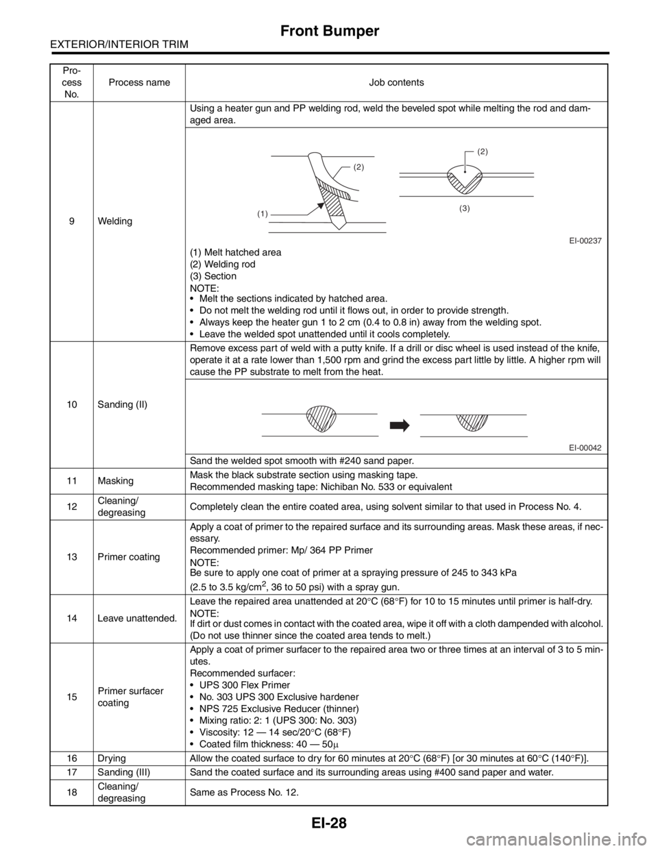
9 WeldingUsing a heater gun and PP welding rod, weld the beveled spot while melting the rod and dam-
aged area.
(1) Melt hatched area
(2) Welding rod
(3) Section
N
OTE:
Melt the sections indicated by hatched area.
Do not melt the welding rod until it flows out, in order to provide strength.
Always keep the heater gun 1 to 2 cm (0.4 to 0.8 in) away from the welding spot.
Leave the welded spot unattended until it cools completely.
10 Sanding (II)Remove excess part of weld with a putty knife. If a drill or disc wheel is used instead of the knife,
operate it at a rate lower than 1,500 rpm and grind the excess part little by little. A higher rpm will
cause the PP substrate to melt from the heat.
Sand the welded spot smooth with #240 sand paper.
11 MaskingMask the black substrate section using masking tape.
Recommended masking tape: Nichiban No. 533 or equivalent
12Cleaning/
degreasingCompletely clean the entire coated area, using solvent similar to that used in Process No. 4.
13 Primer coatingApply a coat of primer to the repaired surface and its surrounding areas. Mask these areas, if nec-
essary.
Recommended primer: Mp/ 364 PP Primer
N
OTE:
Be sure to apply one coat of primer at a spraying pressure of 245 to 343 kPa
(2.5 to 3.5 kg/cm
2, 36 to 50 psi) with a spray gun.
14 Leave unattended.Leave the repaired area unattended at 20°C (68°F) for 10 to 15 minutes until primer is half-dry.
N
OTE:
If dirt or dust comes in contact with the coated area, wipe it off with a cloth dampended with alcohol.
(Do not use thinner since the coated area tends to melt.)
15Primer surfacer
coatingApply a coat of primer surfacer to the repaired area two or three times at an interval of 3 to 5 min-
utes.
Recommended surfacer:
UPS 300 Flex Primer
No. 303 UPS 300 Exclusive hardener
NPS 725 Exclusive Reducer (thinner)
Mixing ratio: 2: 1 (UPS 300: No. 303)
Viscosity: 12 — 14 sec/20°C (68°F)
Coated film thickness: 40 — 50µ
16 Drying Allow the coated surface to dry for 60 minutes at 20°C (68°F) [or 30 minutes at 60°C (140°F)].
17 Sanding (III) Sand the coated surface and its surrounding areas using #400 sand paper and water.
18Cleaning/
degreasingSame as Process No. 12. Pro-
cess
No.Process name Job contents
EI-00237 (1)(2)(2)
(3)
EI-00042