2004 SUBARU FORESTER lock-up
[x] Cancel search: lock-upPage 1106 of 2870
EN(H4SO)-8
ENGINE (DIAGNOSTIC)
General Description
The OBD-II diagnostics procedure is different
from the usual diagnosis procedure. When trouble-
shooting the OBD-II models, connect Subaru Se-
lect Monitor or the OBD-II general scan tool to the
vehicle.
2. ENGINE AND EMISSION CONTROL SYS-
TEM
MFI system is a system that supplies the opti-
mum air-fuel mixture to the engine for all the vari-
ous operating conditions through the use of the
latest electronic technology.
With this system fuel, which is pressurized at a con-
stant pressure, is injected into the intake air pas-
sage of the cylinder head. The injection quantity of
fuel is controlled by an intermittent injection system
where the electro-magnetic injection valve (fuel in-
jector) opens only for a short period of time, de-
pending on the quantity of air required for one cycle
of operation. In actual operation, the injection quan-
tity is determined by the duration of an electric sig-
nal applied to the fuel injector and this permits
simple, yet highly precise metering of the fuel.
Further, all the operating conditions of the engine
are converted into electric signals, and this results
in additional features of the system, such as large
improved adaptability, easier addition of compen-
sating element, etc.The MFI system also has the following features:
Reduced emission of harmful exhaust gases.
Reduced in fuel consumption.
Increased engine output.
Superior acceleration and deceleration.
Excellent engine start and warm-up perfor-
mance by the correction of engine coolant tem-
perature and intake air temperature.3. AUTOMATIC TRANSMISSION AND
ELECTRONIC-HYDRAULIC CONTROL SYS-
TEM
The electronic-hydraulic control system consists of
various sensors and switches, TCM and the hy-
draulic controller including solenoid valves. The
system controls the transmission body including
shift control, lock-up control, overrunning clutch
control, line pressure control and shift timing con-
trol. It also controls the AWD transfer clutch. In oth-
er words, the system detects various operating
conditions from various input signals and sends
output signals to shift solenoids 1, 2 and low clutch
timing solenoid and 2-4 brake timing solenoid, line
pressure duty solenoid, lock-up duty solenoid,
transfer duty solenoid and 2-4 brake duty solenoid
(a total of eight solenoids).
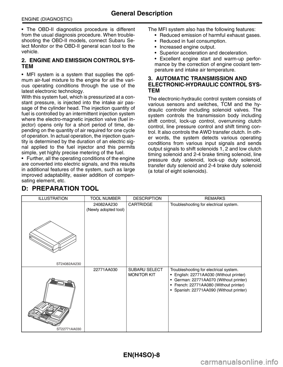
D: PREPARATION TOOL
ILLUSTRATION TOOL NUMBER DESCRIPTION REMARKS
24082AA230
(Newly adopted tool)CARTRIDGE Troubleshooting for electrical system.
22771AA030 SUBARU SELECT
MONITOR KITTroubleshooting for electrical system.
English: 22771AA030 (Without printer)
German: 22771AA070 (Without printer)
French: 22771AA080 (Without printer)
Spanish: 22771AA090 (Without printer)
ST24082AA230
ST22771AA030
Page 1118 of 2870
EN(H4SO)-20
ENGINE (DIAGNOSTIC)
Electrical Component Location
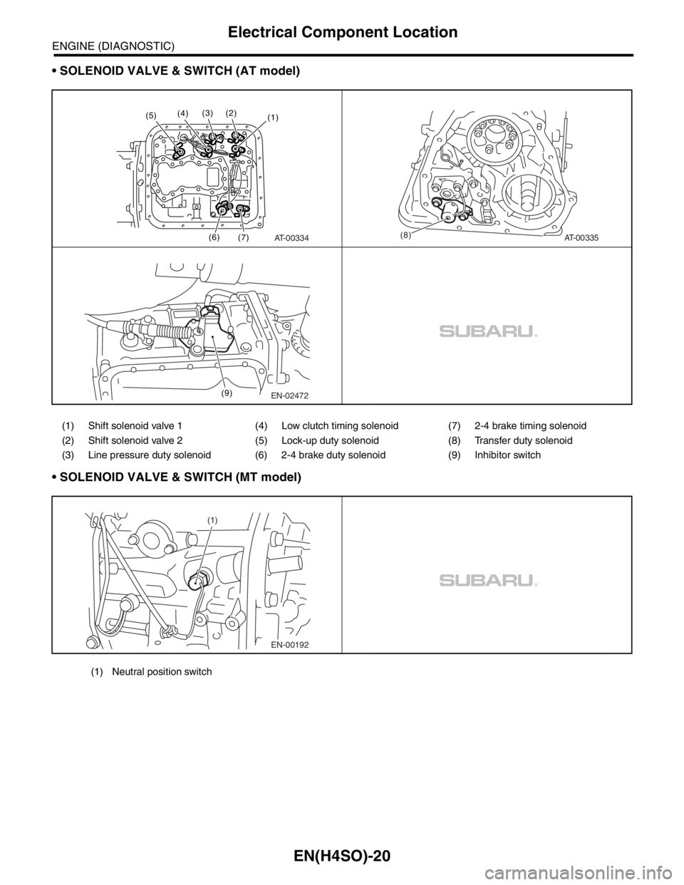
SOLENOID VALVE & SWITCH (AT model)
SOLENOID VALVE & SWITCH (MT model)
(1) Shift solenoid valve 1 (4) Low clutch timing solenoid (7) 2-4 brake timing solenoid
(2) Shift solenoid valve 2 (5) Lock-up duty solenoid (8) Transfer duty solenoid
(3) Line pressure duty solenoid (6) 2-4 brake duty solenoid (9) Inhibitor switch
AT-00334
(1)
(6)
(7) (2)(3)(4)(5)
AT-00335(8)
EN-02472 (9)
EN-00192 (1)
(1) Neutral position switch
Page 1173 of 2870

EN(H4SO)-75
ENGINE (DIAGNOSTIC)
List of Diagnostic Trouble Code (DTC)
P0720 AT Vehicle Speed Sensor Circuit
Malfunction
P0726 Engine Speed Input Circuit Malfunc-
tion
P0731 Gear 1 Incorrect Ratio
P0732 Gear 2 Incorrect Ratio
P0733 Gear 3 Incorrect Ratio
P0734 Gear 4 Incorrect Ratio
P0741 Torque Converter Clutch Circuit Per-
formance or Stuck Off
Diagnostic Trouble Code (DTC).>
P0743 Torque Converter Clutch Circuit Elec-
trical
P0748 Pressure Control Solenoid “A” Elec-
trical
P0753 Shift Solenoid “A” Electrical
P0758 Shift Solenoid “B” Electrical
P0771 Low clutch timing solenoid
P0778 Pressure Control Solenoid “B” Elec-
trical
P0785 Shift/Timing Solenoid
P0851 Neutral Switch Input Circuit Low
(MT MODEL), Diagnostic Procedure with Diagnostic Trouble Code (DTC).>
P0852 Neutral Switch Input Circuit High
P0864 TCM Communication Circuit Range/
Pe r fo r ma nc e
Code (DTC).>
P0865 TCM Communication Circuit Low
P0866 TCM Communication Circuit Low
P1110 Atmospheric Pressure Sensor Circuit
Malfunction (Low Input)
Diagnostic Trouble Code (DTC).>
P1111 Atmospheric Pressure Sensor Circuit
Malfunction (High Input)
Diagnostic Trouble Code (DTC).>
P1134 A/F Sensor Micro-Computer Problem
P1137 O
2 Sensor Circuit (Lambda= 1)
(Bank 1 Sensor 1)
(DTC).>
P1492 EGR Valve Signal #1 Circuit Malfunc-
tion (Low Input)
ble Code (DTC).> DTC Item NOTE
Page 1308 of 2870

EN(H4SO)-210
ENGINE (DIAGNOSTIC)
Diagnostic Procedure with Diagnostic Trouble Code (DTC)
BK:DTC P0741 TORQUE CONVERTER CLUTCH CIRCUIT PERFORMANCE OR
STUCK OFF
DTC DETECTING CONDITION:
Two consecutive driving cycles with fault
TROUBLE SYMPTOM:
No lock-up (after engine warm-up)
No shift or excessive tight corner “braking”
CAUTION:
After repair or replacement of faulty parts, conduct Clear Memory Mode
Step Check Yes No
1 CHECK ANY OTHER DTC ON DISPLAY.Is any other DTC displayed? Inspect the rele-
vant DTC using
“List of Diagnostic
Trouble Code
(DTC)”.
of Diagnostic Trou-
ble Code (DTC).>Go to step 2.
2 CHECK LOCK-UP DUTY SOLENOID CIR-
CUIT.
Check lock-up duty solenoid circuit.
SOLENOID, Diagnostic Procedure with Diag-
nostic Trouble Code (DTC).>Is there any trouble in lock-up
duty solenoid circuit?Repair or replace
the lock-up duty
solenoid circuit.Go to step 3.
3 CHECK THROTTLE POSITION SENSOR
CIRCUIT.
Check the throttle position sensor circuit.
TION SENSOR, Diagnostic Procedure with
Diagnostic Trouble Code (DTC).>Is there any trouble in throttle
position sensor circuit?Repair or replace
the throttle posi-
tion sensor circuit.Go to step 4.
4 CHECK TORQUE CONVERTER TURBINE
SPEED SENSOR CIRCUIT.
Check torque converter turbine speed sensor
circuit.
SENSOR, Diagnostic Procedure with Diagnos-
tic Trouble Code (DTC).>Is there any trouble in torque
converter turbine speed sensor
circuit?Repair or replace
the torque con-
ver ter turbine
speed sensor cir-
cuit.Go to step 5.
5 CHECK ENGINE SPEED INPUT CIRCUIT.
Check engine speed input circuit.
NAL, Diagnostic Procedure with Diagnostic
Trouble Code (DTC).>Is there any trouble in engine
speed input circuit?Repair or replace
the engine speed
input circuit.Go to step 6.
6 CHECK INHIBITOR SWITCH CIRCUIT.
Check inhibitor switch circuit.
Diagnostic Procedure without Diagnostic Trou-
ble Code (DTC).>Is there any trouble in inhibitor
switch circuit?Repair or replace
the inhibitor switch
circuit.Go to step 7.
7 CHECK BRAKE LIGHT SWITCH CIRCUIT.
Check brake light switch circuit.
Diagnostic Procedure without Diagnostic Trou-
ble Code (DTC).>Is there any trouble in brake
light switch circuit?Repair or replace
the brake light
switch circuit.Go to step 8.
Page 1652 of 2870
EN(H4DOTC)-22
ENGINE (DIAGNOSTIC)
Electrical Component Location
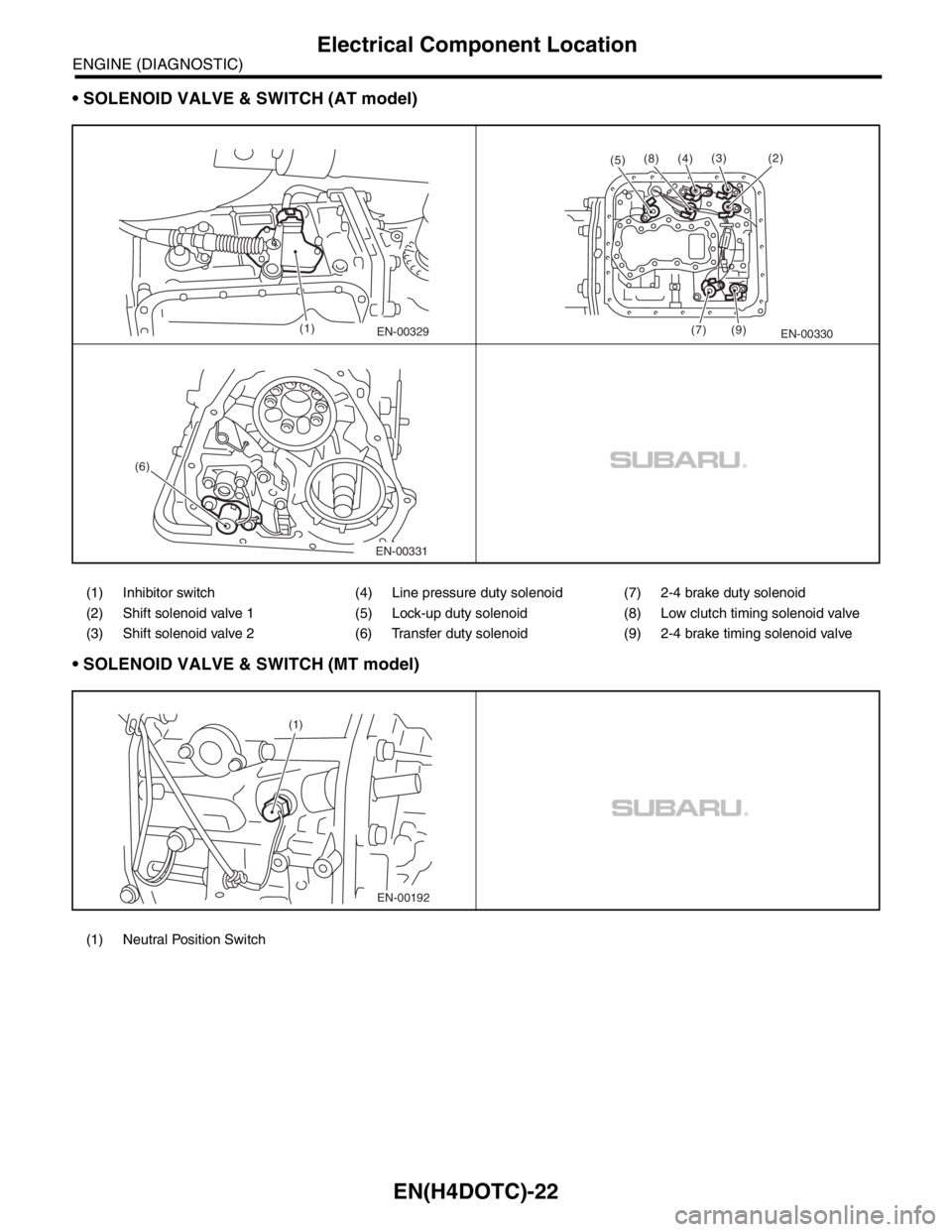
SOLENOID VALVE & SWITCH (AT model)
SOLENOID VALVE & SWITCH (MT model)
(1) Inhibitor switch (4) Line pressure duty solenoid (7) 2-4 brake duty solenoid
(2) Shift solenoid valve 1 (5) Lock-up duty solenoid (8) Low clutch timing solenoid valve
(3) Shift solenoid valve 2 (6) Transfer duty solenoid (9) 2-4 brake timing solenoid valve
(1) Neutral Position Switch
EN-00329(1)
(2)(3)
EN-00330 (4)
(8)
(5)
(7) (9)
EN-00331 (6)
EN-00192 (1)
Page 2321 of 2870
4AT-9
AUTOMATIC TRANSMISSION
General Description
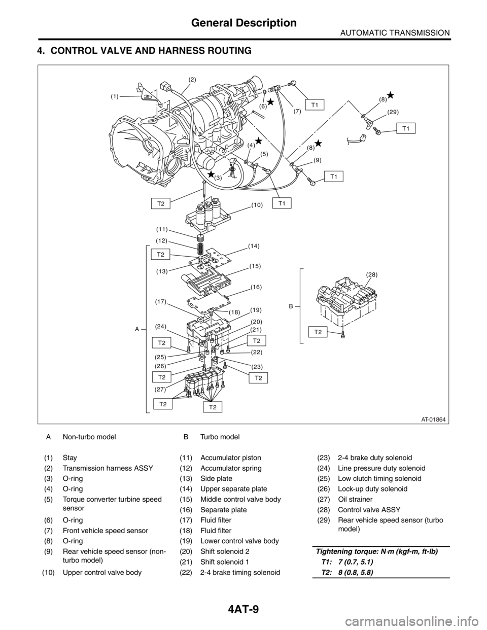
4. CONTROL VALVE AND HARNESS ROUTING
A Non-turbo model B Turbo model
(1) Stay (11) Accumulator piston (23) 2-4 brake duty solenoid
(2) Transmission harness ASSY (12) Accumulator spring (24) Line pressure duty solenoid
(3) O-ring (13) Side plate (25) Low clutch timing solenoid
(4) O-ring (14) Upper separate plate (26) Lock-up duty solenoid
(5) Torque converter turbine speed
sensor(15) Middle control valve body (27) Oil strainer
(16) Separate plate (28) Control valve ASSY
(6) O-ring (17) Fluid filter (29) Rear vehicle speed sensor (turbo
model)
(7) Front vehicle speed sensor (18) Fluid filter
(8) O-ring (19) Lower control valve body
(9) Rear vehicle speed sensor (non-
turbo model)(20) Shift solenoid 2Tightening torque: N
⋅m (kgf-m, ft-lb)
(21) Shift solenoid 1T1: 7 (0.7, 5.1)
(10) Upper control valve body (22) 2-4 brake timing solenoidT2: 8 (0.8, 5.8)
AT-01864
T1T2
T2
T2
T2
T2
T2
T2T2
T2
T1
(1)(2)
(3)(4)
(5)
(6)
(7)
(10)
(11)
(12)
(14)
(13)(15)
(16)
(17)
A(24)(19)
(18)
(20)
(21)
(22)
(23) (26) (25)
(27)
(28)
B
T1
(8)
(9)
T1
(8)
(29)
Page 2344 of 2870

4AT-32
AUTOMATIC TRANSMISSION
Road Test
4. Road Test
A: INSPECTION
1. GENERAL PRECAUTION
Road tests should be conducted to properly diag-
nose the condition of the automatic transmission.
NOTE:
When performing the test, do not exceed posted
speed limit.
2. D RANGE SHIFT FUNCTION
Check shifting between 1st ←→ 2nd ←→ 3rd ←→
4th while driving on normal city streets.
3. D RANGE SHIFT SHOCK
Check the shock level when shifting up during nor-
mal driving.
4. KICK-DOWN FUNCTION
Check kick-down for each gear. Also check the
kick-down shock level.
5. ENGINE BRAKE OPERATION
Check the 3rd gear engine brake when shifting
down from D ←→ 3rd range while driving in 4th
gear of D range [50 — 60 km/h (31 — 37 MPH)].
Check the 2nd gear engine brake when shifting
between 3rd ←→ 2nd range while driving in the 3rd
range of 3rd gear [40 — 50 km/h (25 — 31 MPH)].
Check the 1st gear engine brake when shifting
between 2nd ←→ 1st range while driving in the 2nd
range of 2nd gear [20 — 30 km/h (12 — 19 MPH)].
6. LOCK-UP FUNCTION
Check that rpm does not change sharply when
the axle pedal is lightly depressed when driving on
flat roads at 60 km/h (37 MPH).
Check slip lock-up with following procedure.
Subaru Select Monitor is needed for checking (EC,
EK model).
Before start checking, check that the DTC is not ex-
isted using Subaru Select Monitor. When the DTC
is existed, perform the collective action with DTC
and check that the DTC is not existed again, and
then start the checking.
1) The check performed on flat and straight road or
free roller.
NOTE:
Slip lock-up does not operate when the vehicle is
lifted up, because of not occurring surface resis-
tance.
Also checking on the free roller, check with de-
pressing foot brake lightly to make the checking
easier, because the surface resistance will be defi-
cient2) Connect the Subaru Select Monitor.
3) Check ATF temperature using Subaru Select
Monitor.
NOTE:
ATF temperature is between 50 — 100°C (122
— 212°F).
When the temperature is low, warm-up the ATF
by running the vehicle or etc.
4) Start the engine, and make the lock-up duty be
able to read on data display of Subaru Select Mon-
itor.
5) 35 — 40 Drive the vehicle at a constant speed of
35 — 40 km/h (22 — 25 MPH).
6) Read the lock-up duty while vehicle is running.
Standard value:
25 — 45%
NOTE:
On the free roller, the value sometimes lowers.
Slip lock-up control is not operating when the
lock-up duty is less than 5%, or when the lock-up
duty goes down immediately after starts rise. On
these cases, improper ATF or deterioration of ATF
may be the cause. Check the amount of ATF or re-
place them, and then recheck it.
7. P RANGE OPERATION
Stop the vehicle on an uphill grade of 5% or more
and shift to “P” range. Check that the vehicle does
not move when the parking brake is released.
8. NOISE AND VIBRATION
Check for unusual sounds and vibration while driv-
ing and during shifting.
9. CLIMBING CONTROL FUNCTION
Check that the gear remains in 3rd when going
up a grade.
Check that the gear remains in 3rd when apply-
ing the brakes while going down a grade.
10.TRANSFER CLUTCH
Check tight corner braking when the vehicle started
with steering fully turned.
11.OIL LEAKS
After the driving test, inspect for oil leaks.
Page 2369 of 2870
4AT-56
AUTOMATIC TRANSMISSION
Front Vehicle Speed Sensor
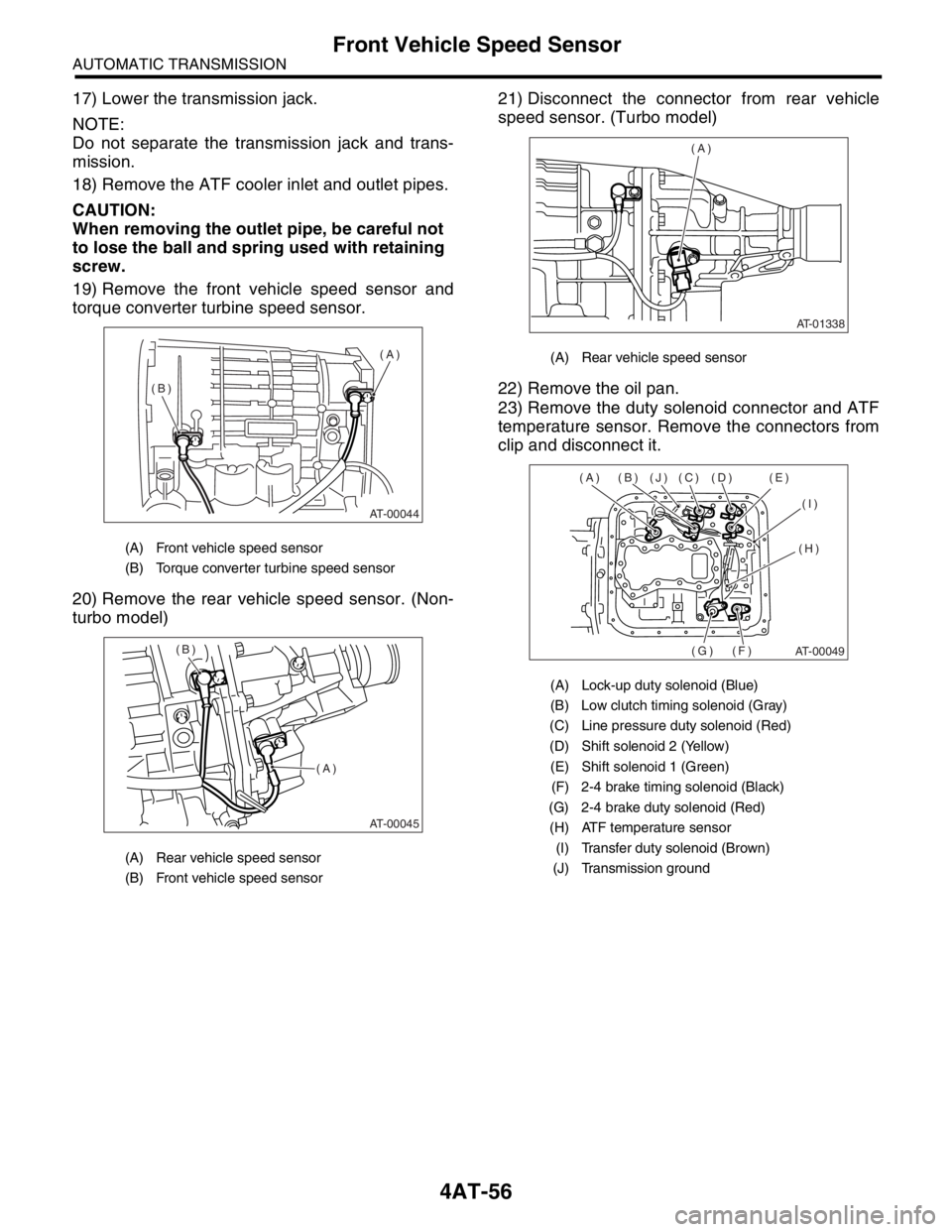
17) Lower the transmission jack.
NOTE:
Do not separate the transmission jack and trans-
mission.
18) Remove the ATF cooler inlet and outlet pipes.
CAUTION:
When removing the outlet pipe, be careful not
to lose the ball and spring used with retaining
screw.
19) Remove the front vehicle speed sensor and
torque converter turbine speed sensor.
20) Remove the rear vehicle speed sensor. (Non-
turbo model)21) Disconnect the connector from rear vehicle
speed sensor. (Turbo model)
22) Remove the oil pan.
23) Remove the duty solenoid connector and ATF
temperature sensor. Remove the connectors from
clip and disconnect it.
(A) Front vehicle speed sensor
(B) Torque converter turbine speed sensor
(A) Rear vehicle speed sensor
(B) Front vehicle speed sensor
AT-00044
(A)
(B)
AT-00045
(A) (B)
(A) Rear vehicle speed sensor
(A) Lock-up duty solenoid (Blue)
(B) Low clutch timing solenoid (Gray)
(C) Line pressure duty solenoid (Red)
(D) Shift solenoid 2 (Yellow)
(E) Shift solenoid 1 (Green)
(F) 2-4 brake timing solenoid (Black)
(G) 2-4 brake duty solenoid (Red)
(H) ATF temperature sensor
(I) Transfer duty solenoid (Brown)
(J) Transmission ground
AT-01338
(A)
AT-00049
(A) (B) (J) (C) (D) (E)
(I)
(H)
(F) (G)