2004 SUBARU FORESTER lock-up
[x] Cancel search: lock-upPage 2635 of 2870
4AT(H4DOTC)-59
AUTOMATIC TRANSMISSION (DIAGNOSTIC)
Diagnostic Procedure with Diagnostic Trouble Code (DTC)
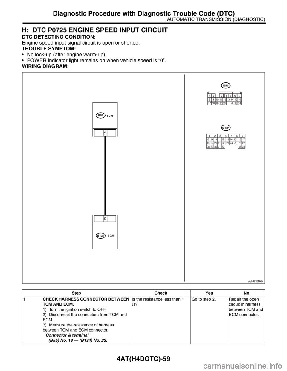
H: DTC P0725 ENGINE SPEED INPUT CIRCUIT
DTC DETECTING CONDITION:
Engine speed input signal circuit is open or shorted.
TROUBLE SYMPTOM:
No lock-up (after engine warm-up).
POWER indicator light remains on when vehicle speed is “0”.
WIRING DIAGRAM:
Step Check Yes No
1 CHECK HARNESS CONNECTOR BETWEEN
TCM AND ECM.
1) Turn the ignition switch to OFF.
2) Disconnect the connectors from TCM and
ECM.
3) Measure the resistance of harness
between TCM and ECM connector.
Connector & terminal
(B55) No. 13 — (B134) No. 23:Is the resistance less than 1
Ω?Go to step 2.Repair the open
circuit in harness
between TCM and
ECM connector.
AT-01846
B55
23
13
B134
ECM
B55
TCM
B134
12
7
8956 3410 11 12
19 20 2113 14 15 16
17 1822
23
24
56 7
82 1
94 310
24 22 23 25 11 12 13 14 15
26 27
2816 17
18 19 20 21
33 34 29
32 30 31
Page 2641 of 2870

4AT(H4DOTC)-65
AUTOMATIC TRANSMISSION (DIAGNOSTIC)
Diagnostic Procedure with Diagnostic Trouble Code (DTC)
O: DTC P0743 TORQUE CONVERTER CLUTCH CIRCUIT ELECTRICAL
DTC DETECTING CONDITION:
Output signal circuit of lock-up duty solenoid is open or shorted.
TROUBLE SYMPTOM:
No “lock-up” (after engine warm-up).
WIRING DIAGRAM:
Step Check Yes No
1 CHECK DTC.Are multiple DTCs indicated? Go to another
DTC.Go to step 2.
2 CHECK HARNESS CONNECTOR BETWEEN
TCM AND TRANSMISSION.
1) Turn the ignition switch to OFF.
2) Disconnect the connector from TCM and
transmission.
3) Measure the resistance of harness
between TCM and transmission connector.
Connector & terminal
(B56) No. 5 — (B11) No. 12:Is the resistance less than 1
Ω?Go to step 3.Repair the open
circuit in harness
between TCM and
transmission con-
nector.
AT-01117
B11
B56
AT12
1
234
56
78
9
1314
15
20
19 1716 10 1112
18
5
B56
B11
AT12
T4 TCM12 4
12 78 956 34
10 11 12 19 20 21
29 30 31 13 14 15 16 17
27 2818
22 23 24 25 26
13
4562
LOCK-UP
DUTY
SOLENOID
TRANSMISSION
Page 2642 of 2870

4AT(H4DOTC)-66
AUTOMATIC TRANSMISSION (DIAGNOSTIC)
Diagnostic Procedure with Diagnostic Trouble Code (DTC)
3 CHECK HARNESS CONNECTOR BETWEEN
TCM AND TRANSMISSION.
Measure the resistance of harness connector
between TCM connector and chassis ground.
Connector & terminal
(B56) No. 5 — Chassis ground:Is the resistance more than 1
MΩ?Go to step 4.Repair the short
circuit in harness
between TCM and
transmission con-
nector.
4 CHECK LOCK-UP DUTY SOLENOID.
Measure the resistance between transmission
connector receptacle’s terminals.
Connector & terminal
(T4) No. 12 — No. 19:Is the resistance 2.0 — 4.5 Ω? Go to step 5.Go to step 11.
5 PREPARE SUBARU SELECT MONITOR.Do you have a Subaru Select
Monitor?Go to step 8.Go to step 6.
6 CHECK OUTPUT SIGNAL EMITTED FROM
TCM.
1) Connect the connectors to TCM and trans-
mission.
2) Lift-up the vehicle and place rigid racks.
NOTE:
Raise all wheels off ground.
3) Start the engine and warm-up the engine
until ATF temperature is above 80°C (176°F).
NOTE:
If ambient temperature is below 0°C (32°F),
drive the vehicle until ATF reaches its operating
temperature.
4) Shift the select lever to “D” range and
slowly increase vehicle speed to 60 km/h
(37 MPH).
NOTE:
The speed difference between front and rear
wheels may light the ABS warning light, but this
indicates no malfunction. When AT control diag-
nosis is finished, perform the ABS memory
clearance procedure of on-board diagnostics
system.
5) Measure the voltage between TCM con-
nector and chassis ground.
Connector & terminal
(B56) No. 5 (+) — Chassis ground (
−):Is the voltage more than 10.5
V?Go to step 7.Go to step 10.
7 CHECK OUTPUT SIGNAL FROM TCM.
1) Return the engine to idling speed and shift
select lever to “N” range.
2) Measure the voltage between TCM con-
nector and chassis ground.
Connector & terminal
(B56) No. 5 (+) — Chassis ground (
−):Is the voltage less than 1 V? Even if the POWER
indicator light was
blinking, the circuit
has returned to a
normal condition at
this time. A tempo-
rary poor contact of
the connector or
harness may be the
cause. Repair the
harness or connec-
tor in TCM and
transmission.Go to step 10. Step Check Yes No
Page 2643 of 2870

4AT(H4DOTC)-67
AUTOMATIC TRANSMISSION (DIAGNOSTIC)
Diagnostic Procedure with Diagnostic Trouble Code (DTC)
8 CHECK OUTPUT SIGNAL FROM TCM US-
ING SUBARU SELECT MONITOR.
1) Connect the connectors to TCM and trans-
mission.
2) Lift-up the vehicle and place rigid racks.
N
OTE:
Raise all wheels off ground.
3) Connect the Subaru Select Monitor to data
link connector.
4) Start the engine and turn Subaru Select
Monitor switch to ON.
5) Start the engine and warm-up the engine
until ATF temperature is above 80°C (176°F).
N
OTE:
If ambient temperature is below 0°C (32°F),
drive the vehicle until ATF reaches its operating
temperature.
6) Read the data of lock-up duty solenoid
using Subaru Select Monitor.
Lock-up duty solenoid is indicated in “%”.
7) Shift the select lever to “D” range and
slowly increase vehicle speed to 60 km/h
(37 MPH). Wheels will lock-up.
NOTE:
The speed difference between front and rear
wheels may light the ABS warning light, but this
indicates no malfunction. When AT control diag-
nosis is finished, perform the ABS memory
clearance procedure of on-board diagnostics
system.
9 CHECK OUTPUT SIGNAL FROM TCM US-
ING SUBARU SELECT MONITOR.
Return the engine to idling speed and shift
select lever to “N” range, read the data.
N
OTE:
The speed difference between front and rear
wheels may light the ABS warning light, but this
indicates no malfunction. When AT control diag-
nosis is finished, perform the ABS memory
clearance procedure of on-board diagnostics
system.
indicator light was
blinking, the circuit
has returned to a
normal condition at
this time. A tempo-
rary poor contact of
the connector or
harness may be the
cause. Repair the
harness or connec-
tor in TCM and
transmission.Go to step 10.
10 CHECK POOR CONTACT.Is there poor contact in lock-up
duty solenoid circuit?Repair poor con-
tact.Replace the TCM.
trol Module
(TCM).> Step Check Yes No
Page 2644 of 2870

4AT(H4DOTC)-68
AUTOMATIC TRANSMISSION (DIAGNOSTIC)
Diagnostic Procedure with Diagnostic Trouble Code (DTC)
11 CHECK LOCK-UP DUTY SOLENOID (IN
TRANSMISSION).
1) Disconnect the transmission connector.
2) Drain the ATF.
CAUTION:
Do not drain the ATF until it cools down.
3) Remove the oil pan and disconnect con-
nector from lock-up duty solenoid.
4) Measure the resistance between lock-up
duty solenoid and transmission ground.
Connector & terminal
(AT12) No. 4 — Transmission ground:Is the resistance 2.0 — 4.5 Ω? Go to step 12.Replace control
valve body.
Valve Body.>
12 CHECK HARNESS CONNECTOR BETWEEN
LOCK-UP DUTY SOLENOID AND TRANS-
MISSION.
Measure the resistance of harness between
lock-up duty solenoid and transmission con-
nector.
Connector & terminal
(T4) No. 12 — (AT12) No. 4:Is the resistance less than 1
Ω?Go to step 13.Repair the open
circuit in harness
between TCM and
transmission con-
nector.
13 CHECK HARNESS CONNECTOR BETWEEN
LOCK-UP DUTY SOLENOID AND TRANS-
MISSION.
Measure the resistance of harness between
transmission connector and transmission
ground.
Connector & terminal
(T4) No. 12 — Transmission ground:Is the resistance more than 1
MΩ?Even if the POWER
indicator light was
blinking, the circuit
has returned to a
normal condition at
this time. A tempo-
rary poor contact of
the connector or
harness may be the
cause. Repair the
harness or connec-
tor in lock-up duty
solenoid and trans-
mission.Repair the short
circuit in harness
between lock-up
duty solenoid and
transmission con-
nector. Step Check Yes No
Page 2664 of 2870
4AT(H4DOTC)-88
AUTOMATIC TRANSMISSION (DIAGNOSTIC)
Diagnostic Procedure with Diagnostic Trouble Code (DTC)
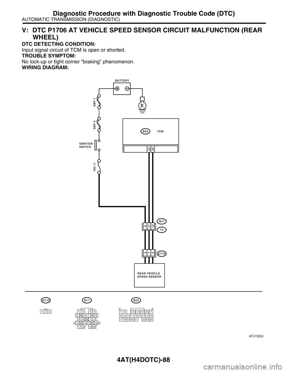
V: DTC P1706 AT VEHICLE SPEED SENSOR CIRCUIT MALFUNCTION (REAR
WHEEL)
DTC DETECTING CONDITION:
Input signal circuit of TCM is open or shorted.
TROUBLE SYMPTOM:
No lock-up or tight corner “braking” phenomenon.
WIRING DIAGRAM:
AT-01850
2324
B11
AT10
T491713
312
B55 TCM BATTERY
IGNITION
SWITCH
REAR VEHICLE
SPEED SENSOR
ESBF-1
SBF-4 NO.11
123
AT10B11
12 34
5678
9
13 14 15
20 19 1716 10 11 1218
B55
12 7
8956 34
10 11 12
19 20 2113 14 15 16
17 18 22 23 24
Page 2702 of 2870

4AT(H4DOTC)-126
AUTOMATIC TRANSMISSION (DIAGNOSTIC)
Symptom Related Diagnostic
15.Symptom Related Diagnostic
A: INSPECTION
Symptom Problem parts
Starter does not rotate when select lever is in “P” or “N” range,
starter rotates when select lever is in “R”, “D”, “3” or “2” range. Inhibitor switch
Select cable
Select lever
Starter motor and harness
Abnormal noise when select lever is in “P” or “N” range. Strainer
Transfer duty solenoid
Oil pump
Drive plate
ATF level too high or too low
Hissing noise occurs during standing start. Strainer
ATF level too high or too low
Noise occurs while driving in “D1”. Final gear
Planetary gear
Reduction gear
Differential gear oil level too high or too low Noise occurs while driving in “D2”.
Noise occurs while driving in “D3”. Final gear
Low & reverse brake
Reduction gear
Differential gear oil level too high or too low
Noise occurs while driving in “D4”. Final gear
Low & reverse brake
Planetary gear
Reduction gear
Differential gear oil level too high or too low
Engine stalls while shifting from “1” range to another. Control valve
Lock-up damper
Engine performance
Input shaft
Vehicle moves when select lever is in “N” range. Select cable
Inhibitor switch
TCM
Low clutch
Shock occurs when select lever is shifted from “N” to “D” range. Accelerator pedal position sensor
ATF temperature sensor
Line pressure linear solenoid
Low clutch duty solenoid
Low clutch
TCM
Harness
Control valve
ATF deterioration
Excessive time lag occurs when select lever is shifted from “N”
to “D” range. Control valve
Low clutch
Line pressure duty solenoid
Seal ring
Front gasket of transmission case
Shock occurs when select lever is shifted from “N” to “R” range. Accelerator pedal position sensor
ATF temperature sensor
Line pressure linear solenoid
TCM
Harness
Control valve
ATF deterioration
Page 2704 of 2870

4AT(H4DOTC)-128
AUTOMATIC TRANSMISSION (DIAGNOSTIC)
Symptom Related Diagnostic
No shift occurs from 1st to 2nd gear.TCM
Rear vehicle speed sensor
Front vehicle speed sensor
Throttle position sensor
Control valve
2-4 brake
No shift occurs from 2nd to 3rd gear.TCM
Control valve
High clutch
No shift occurs from 3rd to 4th gear.TCM
ATF temperature sensor
Control valve
2-4 brake
Engine brake is not effected when select lever is in “3” range. Inhibitor switch
TCM
Throttle position sensor
Control valve
Engine brake is not effected when select lever is in “3” or “2”
range.Control valve
Engine brake is not effected when select lever is in “1” range. Control valve
Low & reverse brake
Shift characteristics are erroneous. Inhibitor switch
TCM
Front vehicle speed sensor
Rear vehicle speed sensor
Throttle position sensor
Control valve
Ground earth
No lock-up occurs.TCM
Torque converter turbine speed sensor
Throttle position sensor
ATF temperature sensor
Control valve
Lock-up facing
Engine speed signal
Parking brake is not effected. Select cable
Select lever
Parking mechanism Shift lever cannot be moved or is hard to move from “P” range.
ATF spurts out. ATF level too high
Differential oil spurts out. Differential gear oil too high
Differential oil level changes excessively. Seal pipe
Double oil seal
Odor is produced from ATF supply pipe.High clutch
2-4 brake
Low & reverse clutch
Reverse clutch
Lock-up facing
ATF deterioration
Shock occurs from 1st to 2nd gear.TCM
Torque converter turbine speed sensor
Accelerator pedal position sensor
2-4 brake duty solenoid
ATF temperature sensor
Line pressure linear solenoid
Control valve
2-4 brake
ATF deterioration
Engine performance
Low & reverse duty solenoid Symptom Problem parts