2004 SUBARU FORESTER coolant reservoir
[x] Cancel search: coolant reservoirPage 732 of 2870
PI-9
PRE-DELIVERY INSPECTION
Pre-delivery Inspection
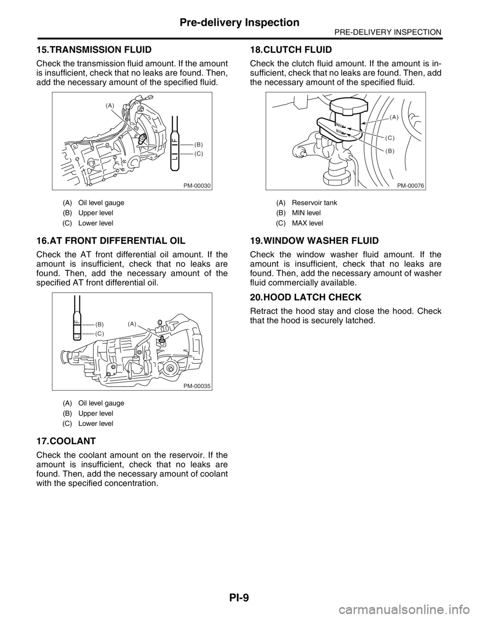
15.TRANSMISSION FLUID
Check the transmission fluid amount. If the amount
is insufficient, check that no leaks are found. Then,
add the necessary amount of the specified fluid.
16.AT FRONT DIFFERENTIAL OIL
Check the AT front differential oil amount. If the
amount is insufficient, check that no leaks are
found. Then, add the necessary amount of the
specified AT front differential oil.
17.COOLANT
Check the coolant amount on the reservoir. If the
amount is insufficient, check that no leaks are
found. Then, add the necessary amount of coolant
with the specified concentration.
18.CLUTCH FLUID
Check the clutch fluid amount. If the amount is in-
sufficient, check that no leaks are found. Then, add
the necessary amount of the specified fluid.
19.WINDOW WASHER FLUID
Check the window washer fluid amount. If the
amount is insufficient, check that no leaks are
found. Then, add the necessary amount of washer
fluid commercially available.
20.HOOD LATCH CHECK
Retract the hood stay and close the hood. Check
that the hood is securely latched.
(A) Oil level gauge
(B) Upper level
(C) Lower level
(A) Oil level gauge
(B) Upper level
(C) Lower level
PM-00030
(B)
(C) (A)
PM-00035
(B)
(C)(A)
(A) Reservoir tank
(B) MIN level
(C) MAX level
PM-00076
(A)
(B) (C)
Page 735 of 2870
PI-12
PRE-DELIVERY INSPECTION
Pre-delivery Inspection
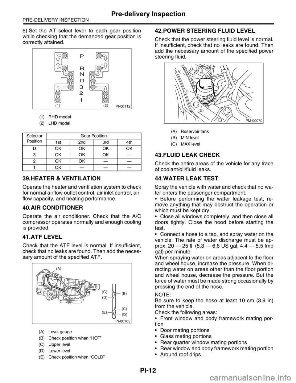
6) Set the AT select lever to each gear position
while checking that the demanded gear position is
correctly attained.
39.HEATER & VENTILATION
Operate the heater and ventilation system to check
for normal airflow outlet control, air inlet control, air-
flow capacity, and heating performance.
40.AIR CONDITIONER
Operate the air conditioner. Check that the A/C
compressor operates normally and enough cooling
is provided.
41.ATF LEVEL
Check that the ATF level is normal. If insufficient,
check that no leaks are found. Then add the neces-
sary amount of the specified ATF.
42.POWER STEERING FLUID LEVEL
Check that the power steering fluid level is normal.
If insufficient, check that no leaks are found. Then
add the necessary amount of the specified power
steering fluid.
43.FLUID LEAK CHECK
Check the entire areas of the vehicle for any trace
of coolant/oil/fluid leaks.
44.WATER LEAK TEST
Spray the vehicle with water and check that no wa-
ter enters the passenger compartment.
Before performing the water leakage test, re-
move anything that may obstruct the operation or
which must be kept dry.
Close all windows completely, and then close all
doors tightly. Close the hood before starting the
test.
Connect a hose to a tap, and spray water on the
vehicle. The rate of water discharge must be ap-
prox. 20 — 252 (5.3 — 6.6 US gal, 4.4 — 5.5 Imp
gal) per minute.
When spraying water on areas adjacent to the floor
and wheel house, increase the pressure. When di-
recting water on areas other than the floor portion
and wheel house, decrease the pressure. But the
force of water must be made strong occasionally by
pressing the end of the hose.
NOTE:
Be sure to keep the hose at least 10 cm (3.9 in)
from the vehicle.
Check the following areas:
Front window and body framework mating por-
tion
Door mating portions
Glass mating portions
Rear quarter window mating portions
Rear window and body framework mating portion
Around roof drips
(1) RHD model
(2) LHD model
Selector
Po si t io nGear Position
1st 2nd 3rd 4th
D OKOKOKOK
3 OKOKOK —
2OKOK——
1OK———
(A) Level gauge
(B) Check position when “HOT”
(C) Upper level
(D) Lower level
(E) Check position when “COLD”
PI-00112(1) (2)
P
R
N
D
3
2
1
PI-00105
COLD
LFHOT LF
(A)
(C)
(D)
(C)
(D)
(E)
(B)
(A) Reservoir tank
(B) MIN level
(C) MAX level
PM-00070
(A)
(C)
(B)
Page 758 of 2870
PM-21
PERIODIC MAINTENANCE SERVICE
Engine Coolant
12.Engine Coolant
A: REPLACEMENT
1. REPLACEMENT OF ENGINE COOLANT
WARNING:
The radiator is of the pressurized type. Do not
attempt to open the radiator cap immediately
after the engine has been stopped.
1) Lift-up the vehicle.
2) Remove the under cover.
3) Place a container under drain pipe.
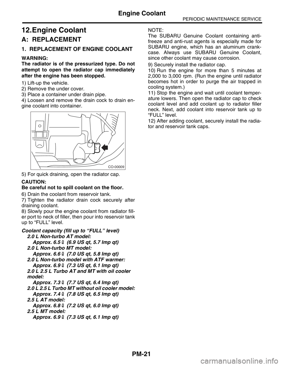
4) Loosen and remove the drain cock to drain en-
gine coolant into container.
5) For quick draining, open the radiator cap.
CAUTION:
Be careful not to spill coolant on the floor.
6) Drain the coolant from reservoir tank.
7) Tighten the radiator drain cock securely after
draining coolant.
8) Slowly pour the engine coolant from radiator fill-
er port to neck of filler, then pour into reservoir tank
up to “FULL” level.
Coolant capacity (fill up to “FULL” level)
2.0 L Non-turbo AT model:
Approx. 6.52 (6.9 US qt, 5.7 Imp qt)
2.0 L Non-turbo MT model:
Approx. 6.62 (7.0 US qt, 5.8 Imp qt)
2.0 L Non-turbo model with ATF warmer:
Approx. 6.92 (7.3 US qt, 6.1 Imp qt)
2.0 L 2.5 L Turbo AT and MT with oil cooler
model:
Approx. 7.32 (7.7 US qt, 6.4 Imp qt)
2.0 L 2.5 L Turbo MT without oil cooler model:
Approx. 7.42 (7.8 US qt, 6.5 Imp qt)
2.5 L AT model:
Approx. 6.82 (7.2 US qt, 6.0 Imp qt)
2.5 L MT model:
Approx. 6.92 (7.3 US qt, 6.1 Imp qt)NOTE:
The SUBARU Genuine Coolant containing anti-
freeze and anti-rust agents is especially made for
SUBARU engine, which has an aluminum crank-
case. Always use SUBARU Genuine Coolant,
since other coolant may cause corrosion.
9) Securely install the radiator cap.
10) Run the engine for more than 5 minutes at
2,000 to 3,000 rpm. (Run the engine until radiator
becomes hot in order to purge the air trapped in
cooling system.)
11) Stop the engine and wait until coolant temper-
ature lowers. Then open the radiator cap to check
coolant level and add coolant up to radiator filler
neck. Next, add coolant into reservoir tank up to
“FULL” level.
12) After adding coolant, securely install the radia-
tor and reservoir tank caps.
CO-00009
Page 800 of 2870
FU(H4SO)-18
FUEL INJECTION (FUEL SYSTEM)
Intake Manifold
10) Connect the brake booster hose.
11) Connect the engine coolant hose (A) to the
throttle body.
12) Connect the PCV hose to the intake manifold.
13) Connect the spark plug cords to the spark
plugs.
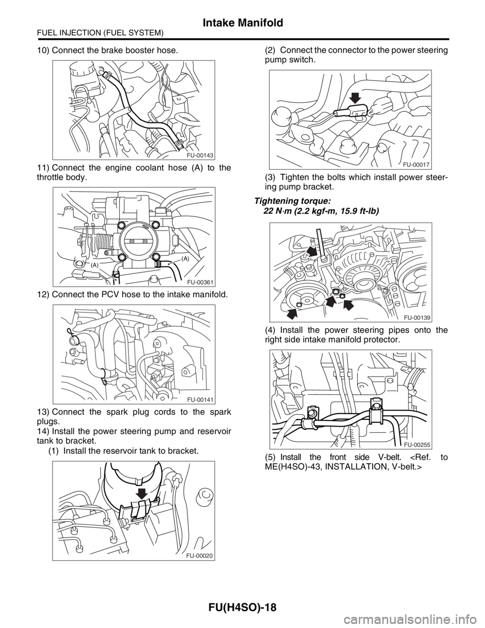
14) Install the power steering pump and reservoir
tank to bracket.
(1) Install the reservoir tank to bracket.(2) Connect the connector to the power steering
pump switch.
(3) Tighten the bolts which install power steer-
ing pump bracket.
Tightening torque:
22 N
⋅m (2.2 kgf-m, 15.9 ft-lb)
(4) Install the power steering pipes onto the
right side intake manifold protector.
(5) Install the front side V-belt.
FU-00143
FU-00361
(A)(A)
FU-00141
FU-00020
FU-00017
FU-00139
FU-00255
Page 984 of 2870

COOLING
CO(H4SO)
Page
1. General Description ....................................................................................2
2. Radiator Fan System ................................................................................13
3. Engine Coolant..........................................................................................19
4. Water Pump ..............................................................................................21
5. Thermostat ................................................................................................26
6. Radiator.....................................................................................................28
7. Radiator Cap .............................................................................................34
8. Radiator Main Fan and Fan Motor ............................................................35
9. Radiator Sub Fan and Fan Motor..............................................................40
10. Reservoir Tank ..........................................................................................41
11. Coolant Filler Tank ....................................................................................42
12. Engine Cooling System Trouble in General ..............................................43
Page 990 of 2870
CO(H4SO)-7
COOLING
General Description
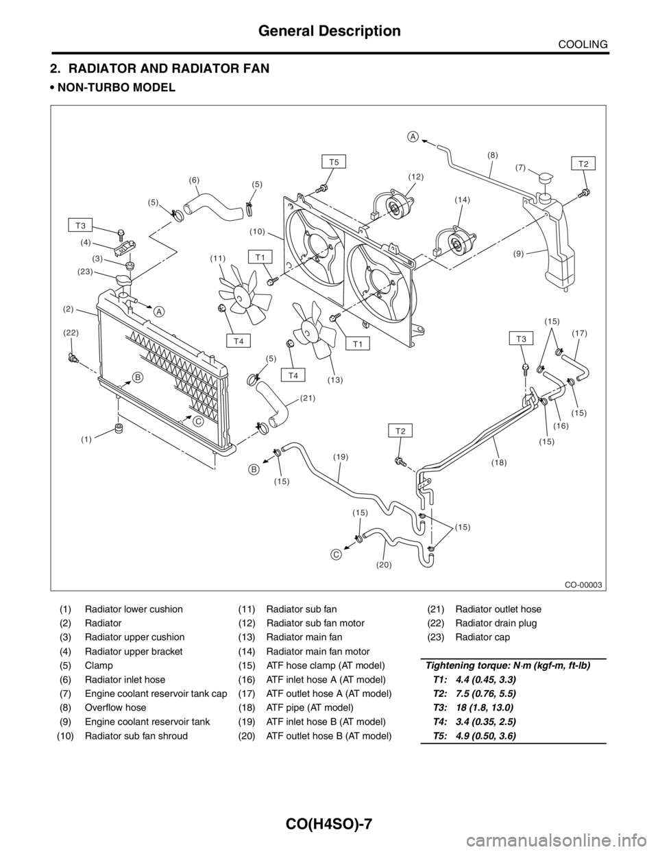
2. RADIATOR AND RADIATOR FAN
NON-TURBO MODEL
(1) Radiator lower cushion (11) Radiator sub fan (21) Radiator outlet hose
(2) Radiator (12) Radiator sub fan motor (22) Radiator drain plug
(3) Radiator upper cushion (13) Radiator main fan (23) Radiator cap
(4) Radiator upper bracket (14) Radiator main fan motor
(5) Clamp (15) ATF hose clamp (AT model)Tightening torque: N
⋅m (kgf-m, ft-lb)
(6) Radiator inlet hose (16) ATF inlet hose A (AT model)T1: 4.4 (0.45, 3.3)
(7) Engine coolant reservoir tank cap (17) ATF outlet hose A (AT model)T2: 7.5 (0.76, 5.5)
(8) Overflow hose (18) ATF pipe (AT model)T3: 18 (1.8, 13.0)
(9) Engine coolant reservoir tank (19) ATF inlet hose B (AT model)T4: 3.4 (0.35, 2.5)
(10) Radiator sub fan shroud (20) ATF outlet hose B (AT model)T5: 4.9 (0.50, 3.6)
CO-00003
(9)
(1)(10)(8)
(2)
T3
T2
T2
T4
T4(14)
(20) (22)(3) (4)
(19)(16)
(18)(7)
(17)
(15) (15)
(15)
(15) (15) (15)(12)
(11)
(13)
T5
T1
T1
(5) (5)
(5)(6)
(21)
A
A
C
T3
B
B
C
(23)
Page 992 of 2870

CO(H4SO)-9
COOLING
General Description
(1) Radiator lower cushion (18) ATF pipe (AT model) (31) Oil cooler inlet hose B (MT model
with oil cooler)
(2) Radiator (19) ATF inlet hose B (AT model)
(3) Radiator upper cushion (20) ATF outlet hose B (AT model) (32) Oil cooler outlet hose B (MT
model with oil cooler)
(4) Radiator upper bracket (21) Radiator outlet hose
(5) Clamp (22) Radiator drain plug (33) Spacer (MT model with oil cooler)
(6) Radiator inlet hose (23) Engine coolant filler tank (34) Cushion (MT model with oil
cooler)
(7) Engine coolant reservoir tank cap (24) Engine coolant filler tank cap
(8) Over flow hose (25) Engine overflow hose (35) Setting washer (MT model with oil
cooler)
(9) Engine coolant reservoir tank (26) Radiator under cover (AT model)
(10) Radiator fan shroud (27) Engine air breather hose
(11) Radiator sub fan (28) Oil cooler inlet hose A (MT model
with oil cooler)Tightening torque: N
⋅m (kgf-m, ft-lb)
(12) Radiator sub fan motorT1: 4.4 (0.45, 3.3)
(13) Radiator main fan (29) Oil cooler outlet hose A (MT
model with oil cooler)T2: 7.5 (0.76, 5.5)
(14) Radiator main fan motorT3: 18 (1.8, 13.0)
(15) ATF hose clamp (AT model) (30) Oil cooler pipe (MT model with oil
cooler)T4: 3.4 (0.35, 2.5)
(16) ATF inlet hose A (AT model)T5: 4.9 (0.50, 3.6)
(17) ATF outlet hose A (AT model)
Page 1002 of 2870
CO(H4SO)-19
COOLING
Engine Coolant
3. Engine Coolant
A: REPLACEMENT
1. DRAINING OF ENGINE COOLANT
1) Lift-up the vehicle.
2) Remove the under cover.
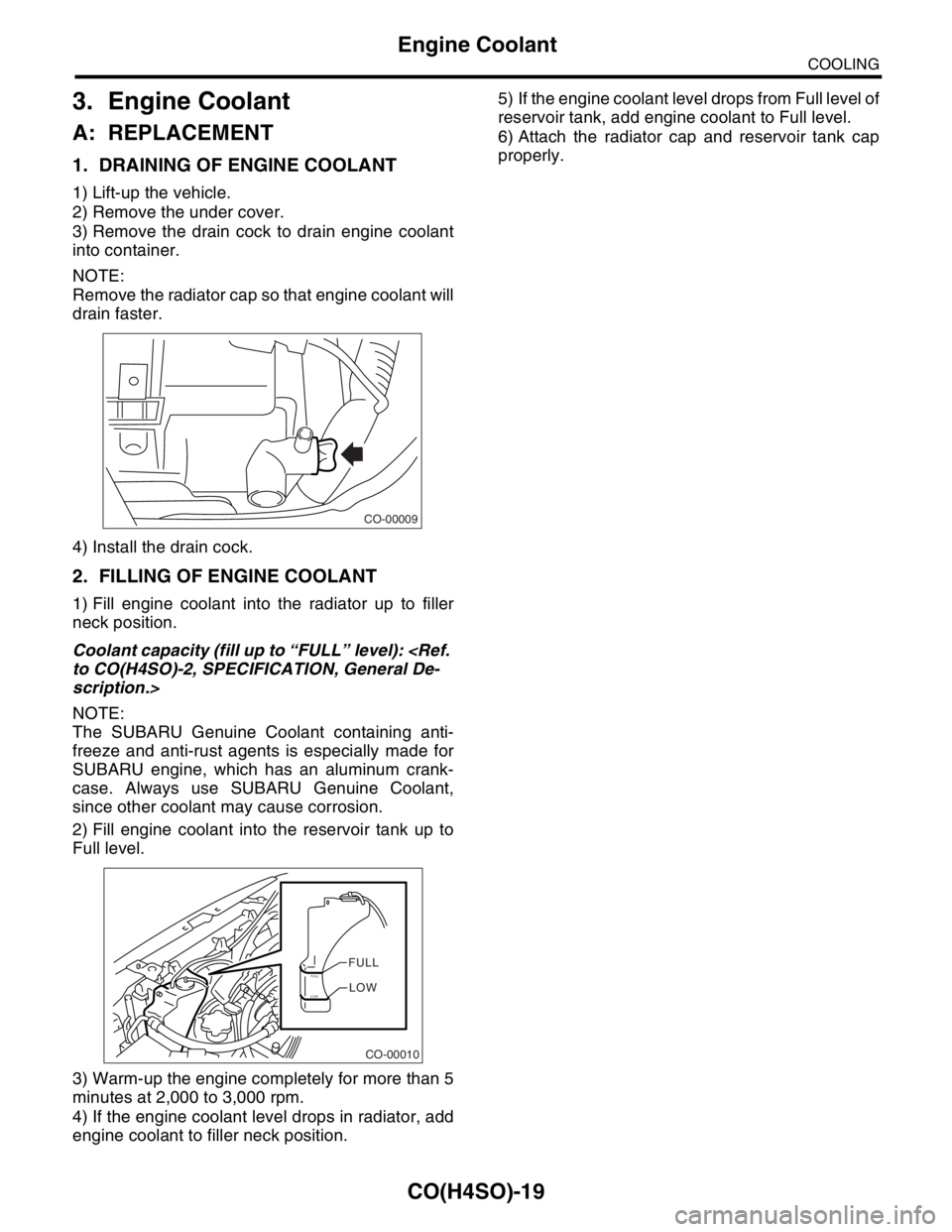
3) Remove the drain cock to drain engine coolant
into container.
NOTE:
Remove the radiator cap so that engine coolant will
drain faster.
4) Install the drain cock.
2. FILLING OF ENGINE COOLANT
1) Fill engine coolant into the radiator up to filler
neck position.
Coolant capacity (fill up to “FULL” level):
scription.>
NOTE:
The SUBARU Genuine Coolant containing anti-
freeze and anti-rust agents is especially made for
SUBARU engine, which has an aluminum crank-
case. Always use SUBARU Genuine Coolant,
since other coolant may cause corrosion.
2) Fill engine coolant into the reservoir tank up to
Full level.
3) Warm-up the engine completely for more than 5
minutes at 2,000 to 3,000 rpm.
4) If the engine coolant level drops in radiator, add
engine coolant to filler neck position.5) If the engine coolant level drops from Full level of
reservoir tank, add engine coolant to Full level.
6) Attach the radiator cap and reservoir tank cap
properly.
CO-00009
CO-00010
FULLFULLLOWLOW