2004 SUBARU FORESTER gearbox
[x] Cancel search: gearboxPage 721 of 2870

RM-6
RECOMMENDED MATERIAL
Recommended Materials
8. ADHESIVES
Use the adhesives shown in the table below, or equivalent.
Grease MT main shaft FX 2200 clutch grease 000040901 —
Clutch master cylinder
push rodSlicolube G-40M 004404003 —
Gear shift lever
Select lever
Clutch operating cyl-
inder
Accelerator pedal
Clutch pedal
Brake pedal
Hill holder
Clutch bearing
Clutch release lever
Steering shaft bear-
ingSUNLIGHT2 003602010 —
Steering gearbox Valiant grease M-2 003608001 —
Disc brake Niglube RX-2 K0779GA102 —
Drum brake
Drum brake wheel
cylinderMolykote No. 7439 003602001 —
Brake pad
Brake shoeMolykote AS-880N K0777YA010 —
Front axle AARi One luber C — —
Front axle AC HTBJ — —
Rear axle BJ Molylex No. 2 003601001 —
Rear axle EBJ NTG2218 — —
Rear axle DOJ VU-3A702 23223GA050 —
Water pump
Door latch
Door strikerSlicolube G-30M 004404002 —
Adhesive Application point Recommended Item number Alternative
Adhesive Windshield and body Dow Automotive’s
Adhesive: Gurit-ESSEX
Betaseal 1502 or equivalent
Glass primer: Betawipe VP
04604 or Betawipe 5001
Paint surface primer: Betap-
rime 5402——
Soft vinyl Cemedine 540 — 3M’s EC-776 EC-847 or EC-1022
(Spray type)
Momentary sealant Cemedine 3000 — Armstrong’s Eastman 910
Inner rearview mirror
baseREPAIR KIT IN MR 65029FC000 — Grease Application point Recommended Item number Alternative
Page 778 of 2870

PM-41
PERIODIC MAINTENANCE SERVICE
Steering System (Power Steering)
26.Steering System (Power
Steering)
A: INSPECTION
1. STEERING WHEEL
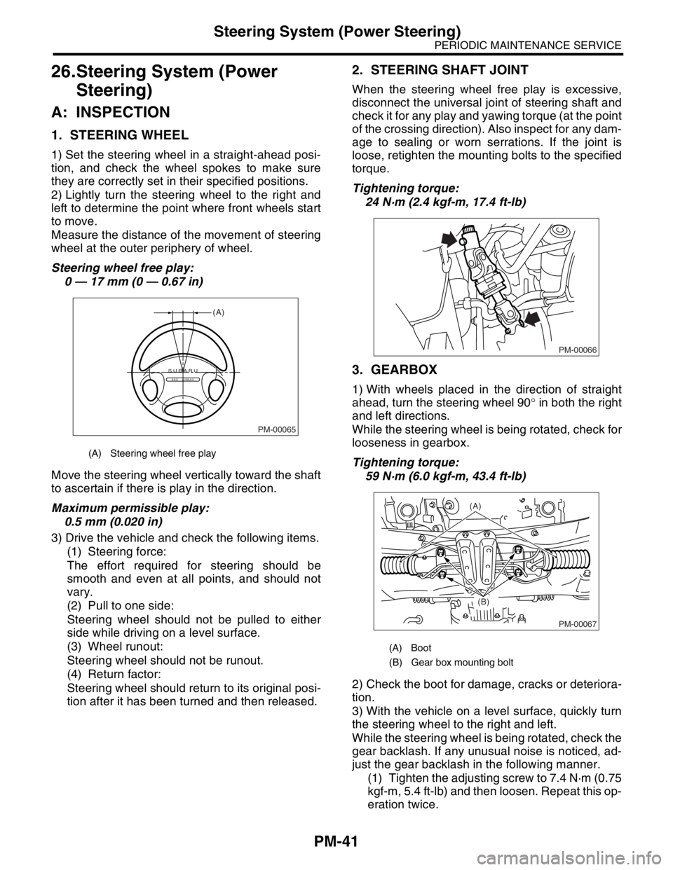
1) Set the steering wheel in a straight-ahead posi-
tion, and check the wheel spokes to make sure
they are correctly set in their specified positions.
2) Lightly turn the steering wheel to the right and
left to determine the point where front wheels start
to move.
Measure the distance of the movement of steering
wheel at the outer periphery of wheel.
Steering wheel free play:
0 — 17 mm (0 — 0.67 in)
Move the steering wheel vertically toward the shaft
to ascertain if there is play in the direction.
Maximum permissible play:
0.5 mm (0.020 in)
3) Drive the vehicle and check the following items.
(1) Steering force:
The effort required for steering should be
smooth and even at all points, and should not
vary.
(2) Pull to one side:
Steering wheel should not be pulled to either
side while driving on a level surface.
(3) Wheel runout:
Steering wheel should not be runout.
(4) Return factor:
Steering wheel should return to its original posi-
tion after it has been turned and then released.
2. STEERING SHAFT JOINT
When the steering wheel free play is excessive,
disconnect the universal joint of steering shaft and
check it for any play and yawing torque (at the point
of the crossing direction). Also inspect for any dam-
age to sealing or worn serrations. If the joint is
loose, retighten the mounting bolts to the specified
torque.
Tightening torque:
24 N·m (2.4 kgf-m, 17.4 ft-lb)
3. GEARBOX
1) With wheels placed in the direction of straight
ahead, turn the steering wheel 90° in both the right
and left directions.
While the steering wheel is being rotated, check for
looseness in gearbox.
Tightening torque:
59 N·m (6.0 kgf-m, 43.4 ft-lb)
2) Check the boot for damage, cracks or deteriora-
tion.
3) With the vehicle on a level surface, quickly turn
the steering wheel to the right and left.
While the steering wheel is being rotated, check the
gear backlash. If any unusual noise is noticed, ad-
just the gear backlash in the following manner.
(1) Tighten the adjusting screw to 7.4 N·m (0.75
kgf-m, 5.4 ft-lb) and then loosen. Repeat this op-
eration twice.
(A) Steering wheel free play
PM-00065
(A)
SUBARUSRS AIRBAG
(A) Boot
(B) Gear box mounting bolt
PM-00066
PM-00067
(A)
(B)
Page 779 of 2870

PM-42
PERIODIC MAINTENANCE SERVICE
Steering System (Power Steering)
(2) Retighten the adjusting screw to 7.4 N·m
(0.75 kgf-m, 5.4 ft-lb) and back off 25°.
(3) Apply Liquid gasket to at least 1/3 of entire
perimeter of adjusting screw thread.
(4) Install the lock nut. While holding the adjust-
ing screw with a wrench, tighten the lock nut us-
ing ST.
ST 926230000 SPANNER
Tightening torque (Lock nut):
39 N·m (4.0 kgf-m, 29 ft-lb)
Hold the adjusting screw with a wrench to pre-
vent it from turning it, while tightening the lock
nut.
4. TIE-ROD
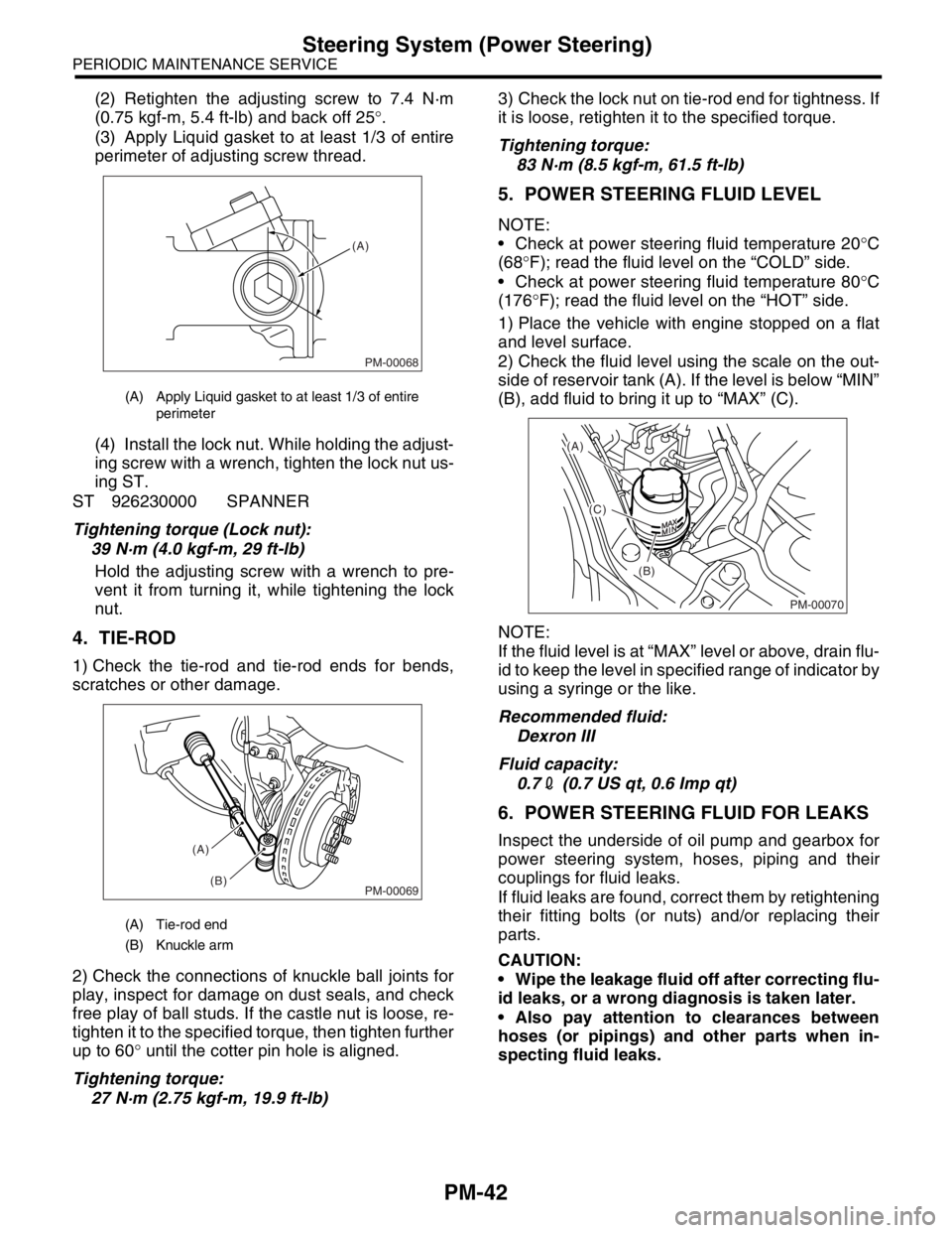
1) Check the tie-rod and tie-rod ends for bends,
scratches or other damage.
2) Check the connections of knuckle ball joints for
play, inspect for damage on dust seals, and check
free play of ball studs. If the castle nut is loose, re-
tighten it to the specified torque, then tighten further
up to 60° until the cotter pin hole is aligned.
Tightening torque:
27 N·m (2.75 kgf-m, 19.9 ft-lb)3) Check the lock nut on tie-rod end for tightness. If
it is loose, retighten it to the specified torque.
Tightening torque:
83 N·m (8.5 kgf-m, 61.5 ft-lb)
5. POWER STEERING FLUID LEVEL
NOTE:
Check at power steering fluid temperature 20°C
(68°F); read the fluid level on the “COLD” side.
Check at power steering fluid temperature 80°C
(176°F); read the fluid level on the “HOT” side.
1) Place the vehicle with engine stopped on a flat
and level surface.
2) Check the fluid level using the scale on the out-
side of reservoir tank (A). If the level is below “MIN”
(B), add fluid to bring it up to “MAX” (C).
NOTE:
If the fluid level is at “MAX” level or above, drain flu-
id to keep the level in specified range of indicator by
using a syringe or the like.
Recommended fluid:
Dexron III
Fluid capacity:
0.72 (0.7 US qt, 0.6 Imp qt)
6. POWER STEERING FLUID FOR LEAKS
Inspect the underside of oil pump and gearbox for
power steering system, hoses, piping and their
couplings for fluid leaks.
If fluid leaks are found, correct them by retightening
their fitting bolts (or nuts) and/or replacing their
parts.
CAUTION:
Wipe the leakage fluid off after correcting flu-
id leaks, or a wrong diagnosis is taken later.
Also pay attention to clearances between
hoses (or pipings) and other parts when in-
specting fluid leaks.
(A) Apply Liquid gasket to at least 1/3 of entire
perimeter
(A) Tie-rod end
(B) Knuckle arm
PM-00068
(A)
PM-00069
(A)
(B)
PM-00070
(A)
(C)
(B)
Page 780 of 2870

PM-43
PERIODIC MAINTENANCE SERVICE
Steering System (Power Steering)
7. HOSES OF OIL PUMP FOR DAMAGES
Check the pressure hose and return hose of oil
pump for crack, swell or damage. Replace the hose
with a new one if necessary.
CAUTION:
Prevent the hoses from revolving and/or turn-
ing when installing hoses.
8. POWER STEERING PIPES FOR DAM-
AGE
Check the power steering pipes for corrosion and
damage.
Replace the pipes with a new one if necessary.
9. GEARBOX BOOTS
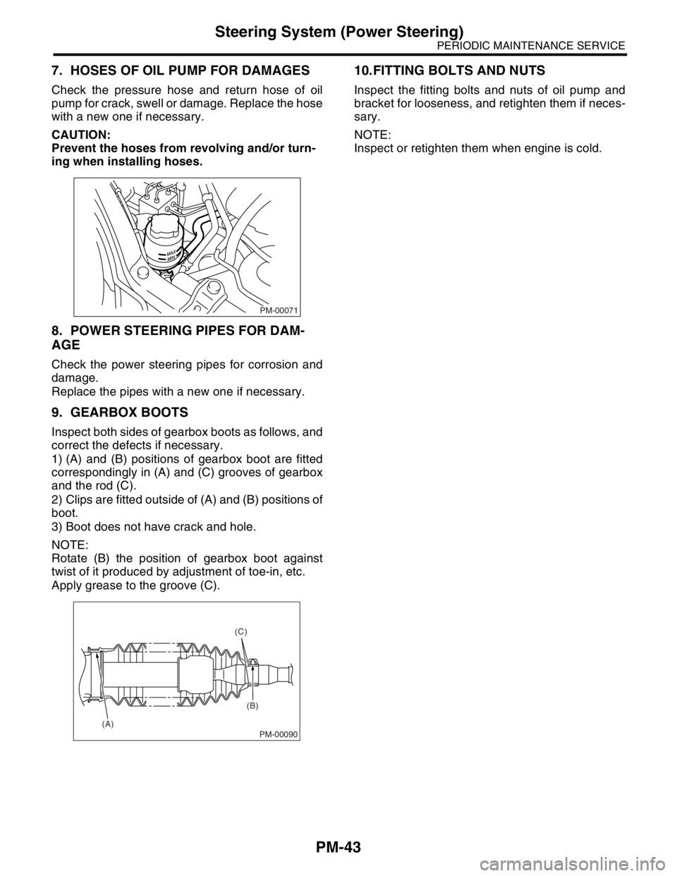
Inspect both sides of gearbox boots as follows, and
correct the defects if necessary.
1) (A) and (B) positions of gearbox boot are fitted
correspondingly in (A) and (C) grooves of gearbox
and the rod (C).
2) Clips are fitted outside of (A) and (B) positions of
boot.
3) Boot does not have crack and hole.
NOTE:
Rotate (B) the position of gearbox boot against
twist of it produced by adjustment of toe-in, etc.
Apply grease to the groove (C).
10.FITTING BOLTS AND NUTS
Inspect the fitting bolts and nuts of oil pump and
bracket for looseness, and retighten them if neces-
sary.
NOTE:
Inspect or retighten them when engine is cold.
PM-00071
PM-00090
(C)
(B)
(A)
Page 1598 of 2870

EX(H4DOTC)-12
EXHAUST
Center Exhaust Pipe
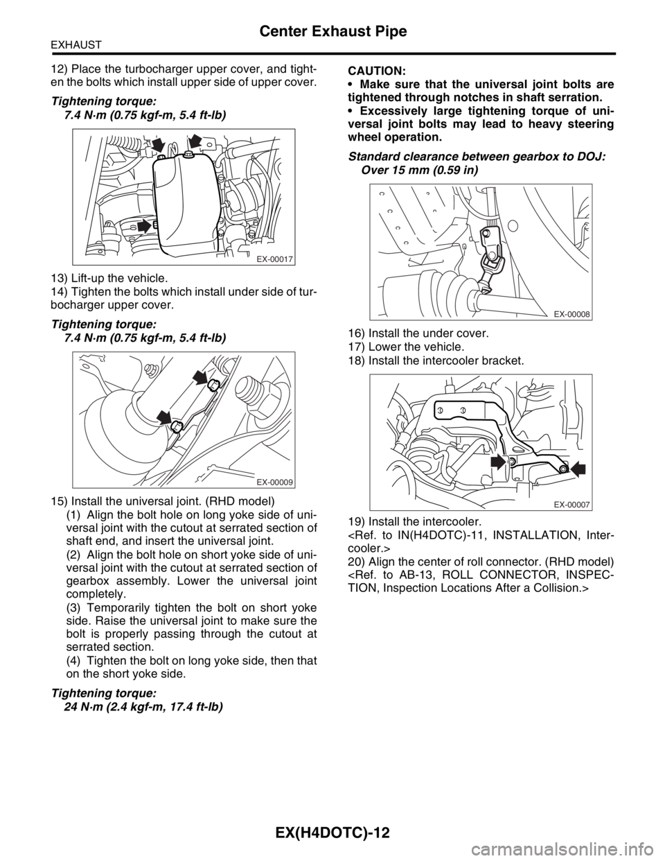
12) Place the turbocharger upper cover, and tight-
en the bolts which install upper side of upper cover.
Tightening torque:
7.4 N·m (0.75 kgf-m, 5.4 ft-lb)
13) Lift-up the vehicle.
14) Tighten the bolts which install under side of tur-
bocharger upper cover.
Tightening torque:
7.4 N·m (0.75 kgf-m, 5.4 ft-lb)
15) Install the universal joint. (RHD model)
(1) Align the bolt hole on long yoke side of uni-
versal joint with the cutout at serrated section of
shaft end, and insert the universal joint.
(2) Align the bolt hole on short yoke side of uni-
versal joint with the cutout at serrated section of
gearbox assembly. Lower the universal joint
completely.
(3) Temporarily tighten the bolt on short yoke
side. Raise the universal joint to make sure the
bolt is properly passing through the cutout at
serrated section.
(4) Tighten the bolt on long yoke side, then that
on the short yoke side.
Tightening torque:
24 N·m (2.4 kgf-m, 17.4 ft-lb)CAUTION:
Make sure that the universal joint bolts are
tightened through notches in shaft serration.
Excessively large tightening torque of uni-
versal joint bolts may lead to heavy steering
wheel operation.
Standard clearance between gearbox to DOJ:
Over 15 mm (0.59 in)
16) Install the under cover.
17) Lower the vehicle.
18) Install the intercooler bracket.
19) Install the intercooler.
20) Align the center of roll connector. (RHD model)
EX-00017
EX-00009
EX-00008
EX-00007