2004 SUBARU FORESTER engine oil
[x] Cancel search: engine oilPage 768 of 2870
PM-31
PERIODIC MAINTENANCE SERVICE
Brake Line
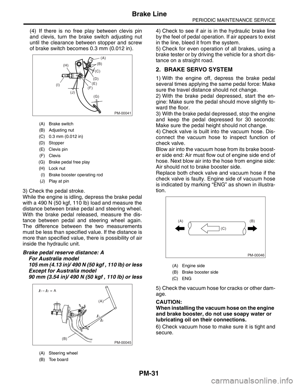
(4) If there is no free play between clevis pin
and clevis, turn the brake switch adjusting nut
until the clearance between stopper and screw
of brake switch becomes 0.3 mm (0.012 in).
3) Check the pedal stroke.
While the engine is idling, depress the brake pedal
with a 490 N (50 kgf, 110 lb) load and measure the
distance between brake pedal and steering wheel.
With the brake pedal released, measure the dis-
tance between pedal and steering wheel again.
The difference between the two measurements
must be less than specified value. If the distance is
more than specified value, there is possibility of air
inside the hydraulic unit.
Brake pedal reserve distance: A
For Australia model
105 mm (4.13 in)/ 490 N (50 kgf , 110 lb) or less
Except for Australia model
90 mm (3.54 in)/ 490 N (50 kgf , 110 lb) or less4) Check to see if air is in the hydraulic brake line
by the feel of pedal operation. If air appears to exist
in the line, bleed it from the system.
5) Check for even operation of all brakes, using a
brake tester or by driving the vehicle for a short dis-
tance on a straight road.
2. BRAKE SERVO SYSTEM
1) With the engine off, depress the brake pedal
several times applying the same pedal force: Make
sure the travel distance should not change.
2) With the brake pedal depressed, start the en-
gine: Make sure the pedal should move slightly to-
ward the floor.
3) With the brake pedal depressed, stop the engine
and keep the pedal depressed for 30 seconds:
Make sure the pedal height should not change.
4) Check valve is built into the vacuum hose. Dis-
connect the vacuum hose to inspect function of
check valve.
Blow air into the vacuum hose from its brake boost-
er side end: Air must flow out of engine side end of
hose. Next blow air into the hose from engine side:
Air should not to brake booster side.
Replace both check valve and vacuum hose if the
check valve is faulty. Engine side of vacuum hose
is indicated by marking “ENG” as shown in illustra-
tion.
5) Check the vacuum hose for cracks or other dam-
age.
CAUTION:
When installing the vacuum hose on the engine
and brake booster, do not use soapy water or
lubricating oil on their connections.
6) Check vacuum hose to make sure it is tight and
secure.
(A) Brake switch
(B) Adjusting nut
(C) 0.3 mm (0.012 in)
(D) Stopper
(E) Clevis pin
(F) Clevis
(G) Brake pedal free play
(H) Lock nut
(I) Brake booster operating rod
(J) Play at pin
(A) Steering wheel
(B) Toe board
PM-00041
(B)
(G) (H)
(I)
(J)(C)
(D)
(E)
(F)(A)
PM-00045(B)(A) = A
1
12
2
(A) Engine side
(B) Brake booster side
(C) ENG
PM-00046
(B)
(C) (A)
Page 779 of 2870
PM-42
PERIODIC MAINTENANCE SERVICE
Steering System (Power Steering)
(2) Retighten the adjusting screw to 7.4 N·m
(0.75 kgf-m, 5.4 ft-lb) and back off 25°.
(3) Apply Liquid gasket to at least 1/3 of entire
perimeter of adjusting screw thread.
(4) Install the lock nut. While holding the adjust-
ing screw with a wrench, tighten the lock nut us-
ing ST.
ST 926230000 SPANNER
Tightening torque (Lock nut):
39 N·m (4.0 kgf-m, 29 ft-lb)
Hold the adjusting screw with a wrench to pre-
vent it from turning it, while tightening the lock
nut.
4. TIE-ROD
1) Check the tie-rod and tie-rod ends for bends,
scratches or other damage.
2) Check the connections of knuckle ball joints for
play, inspect for damage on dust seals, and check
free play of ball studs. If the castle nut is loose, re-
tighten it to the specified torque, then tighten further
up to 60° until the cotter pin hole is aligned.
Tightening torque:
27 N·m (2.75 kgf-m, 19.9 ft-lb)3) Check the lock nut on tie-rod end for tightness. If
it is loose, retighten it to the specified torque.
Tightening torque:
83 N·m (8.5 kgf-m, 61.5 ft-lb)
5. POWER STEERING FLUID LEVEL
NOTE:
Check at power steering fluid temperature 20°C
(68°F); read the fluid level on the “COLD” side.
Check at power steering fluid temperature 80°C
(176°F); read the fluid level on the “HOT” side.
1) Place the vehicle with engine stopped on a flat
and level surface.
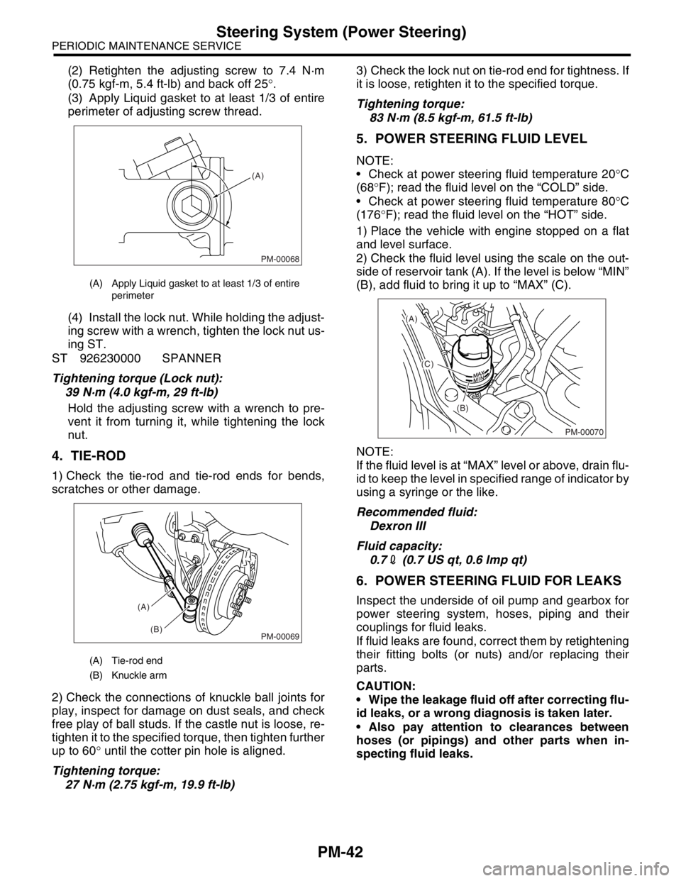
2) Check the fluid level using the scale on the out-
side of reservoir tank (A). If the level is below “MIN”
(B), add fluid to bring it up to “MAX” (C).
NOTE:
If the fluid level is at “MAX” level or above, drain flu-
id to keep the level in specified range of indicator by
using a syringe or the like.
Recommended fluid:
Dexron III
Fluid capacity:
0.72 (0.7 US qt, 0.6 Imp qt)
6. POWER STEERING FLUID FOR LEAKS
Inspect the underside of oil pump and gearbox for
power steering system, hoses, piping and their
couplings for fluid leaks.
If fluid leaks are found, correct them by retightening
their fitting bolts (or nuts) and/or replacing their
parts.
CAUTION:
Wipe the leakage fluid off after correcting flu-
id leaks, or a wrong diagnosis is taken later.
Also pay attention to clearances between
hoses (or pipings) and other parts when in-
specting fluid leaks.
(A) Apply Liquid gasket to at least 1/3 of entire
perimeter
(A) Tie-rod end
(B) Knuckle arm
PM-00068
(A)
PM-00069
(A)
(B)
PM-00070
(A)
(C)
(B)
Page 780 of 2870
PM-43
PERIODIC MAINTENANCE SERVICE
Steering System (Power Steering)
7. HOSES OF OIL PUMP FOR DAMAGES
Check the pressure hose and return hose of oil
pump for crack, swell or damage. Replace the hose
with a new one if necessary.
CAUTION:
Prevent the hoses from revolving and/or turn-
ing when installing hoses.
8. POWER STEERING PIPES FOR DAM-
AGE
Check the power steering pipes for corrosion and
damage.
Replace the pipes with a new one if necessary.
9. GEARBOX BOOTS
Inspect both sides of gearbox boots as follows, and
correct the defects if necessary.
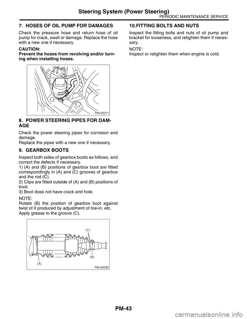
1) (A) and (B) positions of gearbox boot are fitted
correspondingly in (A) and (C) grooves of gearbox
and the rod (C).
2) Clips are fitted outside of (A) and (B) positions of
boot.
3) Boot does not have crack and hole.
NOTE:
Rotate (B) the position of gearbox boot against
twist of it produced by adjustment of toe-in, etc.
Apply grease to the groove (C).
10.FITTING BOLTS AND NUTS
Inspect the fitting bolts and nuts of oil pump and
bracket for looseness, and retighten them if neces-
sary.
NOTE:
Inspect or retighten them when engine is cold.
PM-00071
PM-00090
(C)
(B)
(A)
Page 799 of 2870
FU(H4SO)-17
FUEL INJECTION (FUEL SYSTEM)
Intake Manifold
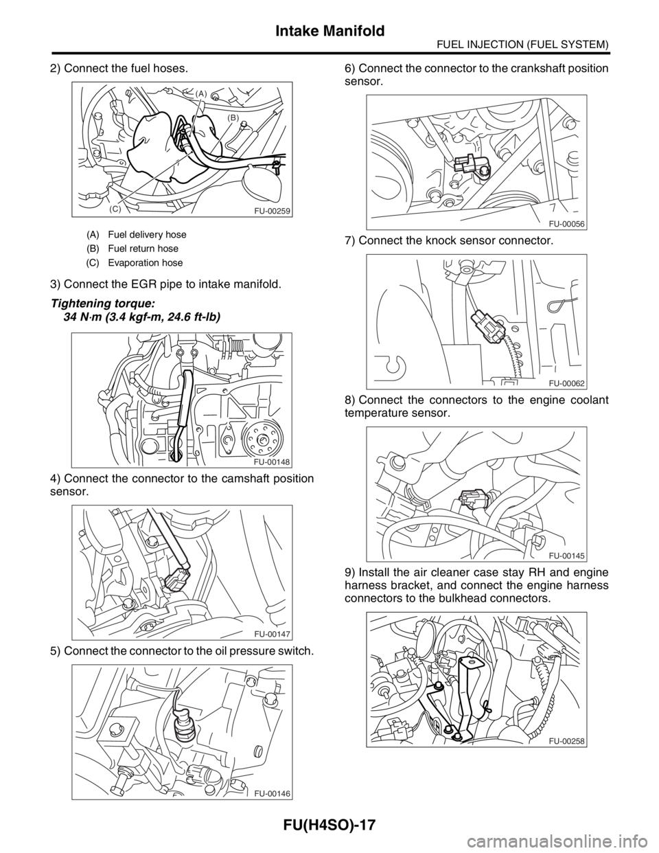
2) Connect the fuel hoses.
3) Connect the EGR pipe to intake manifold.
Tightening torque:
34 N
⋅m (3.4 kgf-m, 24.6 ft-lb)
4) Connect the connector to the camshaft position
sensor.
5) Connect the connector to the oil pressure switch.6) Connect the connector to the crankshaft position
sensor.
7) Connect the knock sensor connector.
8) Connect the connectors to the engine coolant
temperature sensor.
9) Install the air cleaner case stay RH and engine
harness bracket, and connect the engine harness
connectors to the bulkhead connectors.
(A) Fuel delivery hose
(B) Fuel return hose
(C) Evaporation hose
(B) (A)
(C)
FU-00259
FU-00148
FU-00147
FU-00146
FU-00056
FU-00062
FU-00145
FU-00258
Page 801 of 2870
FU(H4SO)-19
FUEL INJECTION (FUEL SYSTEM)
Intake Manifold
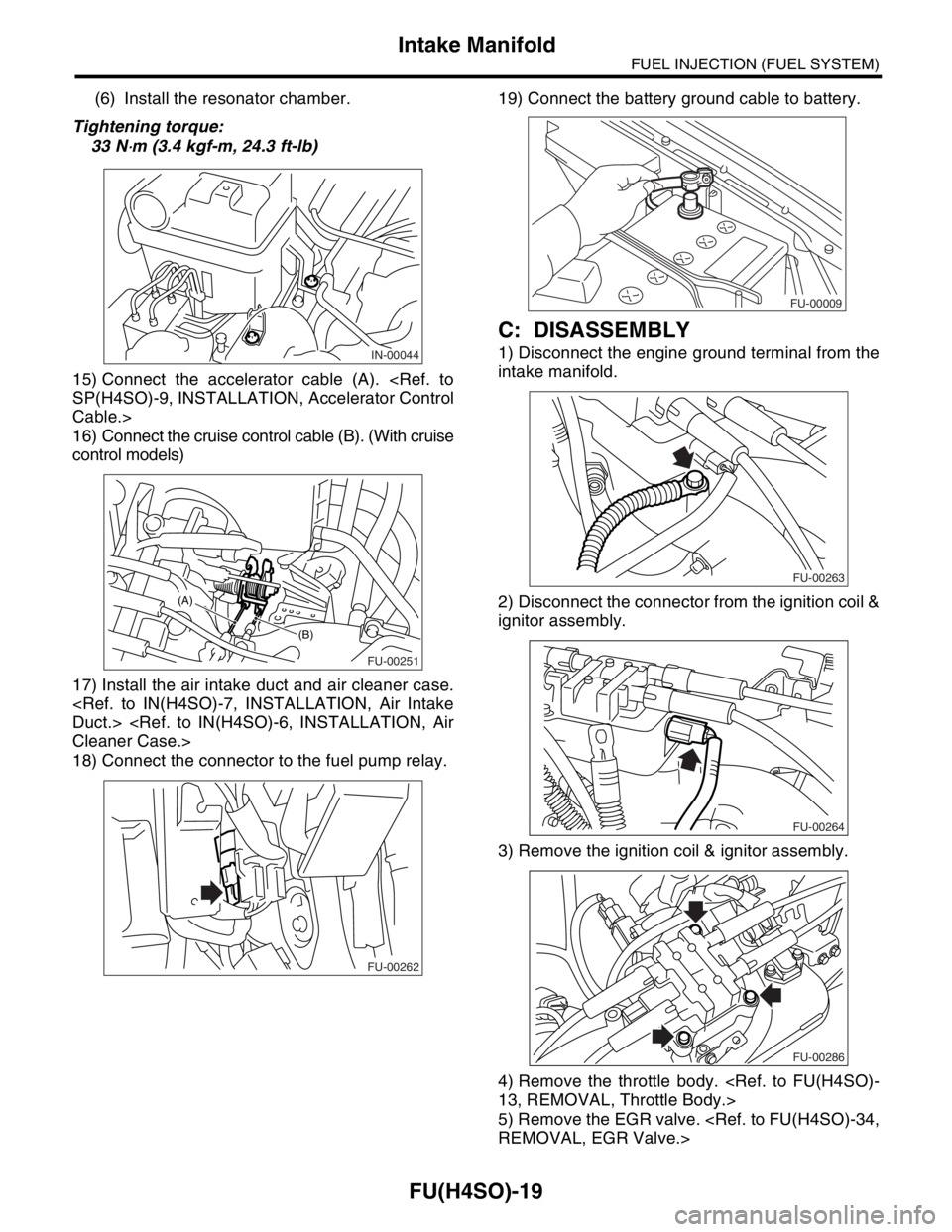
(6) Install the resonator chamber.
Tightening torque:
33 N
⋅m (3.4 kgf-m, 24.3 ft-lb)
15) Connect the accelerator cable (A).
Cable.>
16) Connect the cruise control cable (B). (With cruise
control models)
17) Install the air intake duct and air cleaner case.
18) Connect the connector to the fuel pump relay.19) Connect the battery ground cable to battery.
C: DISASSEMBLY
1) Disconnect the engine ground terminal from the
intake manifold.
2) Disconnect the connector from the ignition coil &
ignitor assembly.
3) Remove the ignition coil & ignitor assembly.
4) Remove the throttle body.
5) Remove the EGR valve.
FU-00251
(B)
(A)
FU-00262
FU-00009
FU-00263
FU-00264
FU-00286
Page 806 of 2870
FU(H4SO)-24
FUEL INJECTION (FUEL SYSTEM)
Intake Manifold
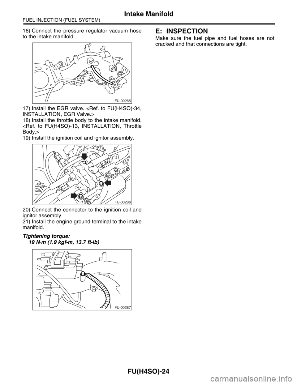
16) Connect the pressure regulator vacuum hose
to the intake manifold.
17) Install the EGR valve.
18) Install the throttle body to the intake manifold.
19) Install the ignition coil and ignitor assembly.
20) Connect the connector to the ignition coil and
ignitor assembly.
21) Install the engine ground terminal to the intake
manifold.
Tightening torque:
19 N
⋅m (1.9 kgf-m, 13.7 ft-lb)
E: INSPECTION
Make sure the fuel pipe and fuel hoses are not
cracked and that connections are tight.
FU-00265
FU-00286
FU-00287
Page 870 of 2870

MECHANICAL
ME(H4SO)
Page
1. General Description ....................................................................................2
2. Compression .............................................................................................25
3. Idle Speed .................................................................................................26
4. Ignition Timing ...........................................................................................27
5. Intake Manifold Vacuum............................................................................28
6. Engine Oil Pressure ..................................................................................29
7. Fuel Pressure ............................................................................................30
8. Valve Clearance ........................................................................................31
9. Engine Assembly ......................................................................................34
10. Engine Mounting .......................................................................................41
11. Preparation for Overhaul ...........................................................................42
12. V-belt .........................................................................................................43
13. Crank Pulley ..............................................................................................45
14. Timing Belt Cover......................................................................................47
15. Timing Belt ................................................................................................48
16. Cam Sprocket ...........................................................................................53
17. Crank Sprocket .........................................................................................55
18. Valve Rocker Assembly ............................................................................56
19. Camshaft ...................................................................................................58
20. Cylinder Head ...........................................................................................62
21. Cylinder Block ...........................................................................................69
22. Engine Trouble in General ........................................................................91
23. Engine Noise .............................................................................................96
Page 871 of 2870

ME(H4SO)-2
MECHANICAL
General Description
1. General Description
A: SPECIFICATION
NOTE:
STD: Standard I.D.: Inner Diameter O.D.: Outer Diameter US: Undersize OS: Oversize
EngineModel 2.0 L 2.5 L
Ty p eHorizontally opposed, liquid cooled, 4-cylinder, 4-stroke gaso-
line engine
Valve arrangement Belt driven, single over-head camshaft, 4-valve/cylinder
Bore×Stroke mm (in) 92×75 (3.62×2.95)99.5×79.0
(3.917×3.110)
Displacement
cm
3 (cu in)1,994 (121.67) 2,457 (150)
Compression ratio 10.0
Compression pressure
(at 200 — 300 rpm)kPa (kg/cm
2, psi)1,079 — 1,275 (11.0 — 13.0, 156 — 185)
Number of piston rings Pressure ring: 2, Oil ring: 1
Intake valve timingOpen 4° BTDC 1° BTDC
Close 48° ABDC 51° ABDC
Exhaust valve timingOpen 48° BBDC 50° BBDC
Close 4° AT D C 6° AT D C
Valve clearance Intake mm (in) 0.20±0.04 (0.0079±0.0016)
Exhaust mm (in) 0.25±0.04 (0.0098±0.0016)
Idling speed [at neutral position on
MT, or “P” or “N” range on AT]rpm650±100 (No load)
850±100 (A/C switch ON)
Firing order 1 → 3 → 2 → 4
Ignition timing BTDC/rpm 10°±10°/650
Belt
tensioner
adjusterProtrusion of adjuster rod mm (in) 5.7 — 6.7 (0.224 — 0.263)
Belt
tensionerSpacer O.D. mm (in) 17.955 — 17.975 (0.7069 — 0.7077)
Tensioner bush I.D. mm (in) 18.00 — 18.08 (0.7087 — 0.7118)
Clearance between spacer and bush mm (in)STD 0.025 — 0.125 (0.0010 — 0.0049)
Limit 0.175 (0.0069)
Side clearance of spacer mm (in)STD 0.20 — 0.55 (0.0079 — 0.0217)
Limit 0.81 (0.0319)
Valve rocker
armClearance between shaft and arm mm (in)STD 0.020 — 0.054 (0.0008 — 0.0021)
Limit 0.10 (0.0039)
CamshaftBend limit mm (in) 0.025 (0.0010)
Thrust clearance mm (in)STD 0.030 — 0.090 (0.0012 — 0.0035)
Limit 0.10 (0.0039)
Cam lobe height mm (in)2.0 LIntakeSTD 38.732 — 38.832 (1.5249 — 1.5288)
Limit 38.632 (1.5209)
ExhaustSTD 39.259 — 39.359 (1.5456 — 1.5496)
Limit 39.157 (1.5417)
2.5 LIntakeSTD 39.485 — 39.585 (1.5545 — 1.5585)
Limit 39.385 (1.5506)
ExhaustSTD 39.259 — 39.359 (1.5456 — 1.5496)
Limit 39.159 (1.5417)
Camshaft journal O.D. mm (in) 31.928 — 31.945 (1.2570 — 1.2577)
Camshaft journal hole I.D. (Cylinder head) mm (in) 32.000 — 32.018 (1.2598 — 1.2605)
Oil clearance mm (in)STD 0.055 — 0.090 (0.0022 — 0.0035)
Limit 0.10 (0.0039)