Page 323 of 2870
COMMUNICATION SYSTEM
COM
Page
1. General Description ....................................................................................2
2. Horn System ...............................................................................................3
3. Horn ............................................................................................................4
4. Horn Switch .................................................................................................5
Page 325 of 2870
COM-3
COMMUNICATION SYSTEM
Horn System
2. Horn System
A: WIRING DIAGRAM
1. HORN
tem.>
B: INSPECTION
1. HORN RELAY
Measure the horn relay resistance between termi-
nals (indicated in table below) when connecting ter-
minal No. 4 to battery positive terminal and terminal
No. 3 to battery negative terminal.
Current Terminal No. Standard
Flow
1 and 2Less than 1Ω
No Flow More than 1MΩ
COM00001
(1)
(2) (1)
(4)(2)
(3)
(3)(4)
Page 326 of 2870
COM-4
COMMUNICATION SYSTEM
Horn
3. Horn
A: REMOVAL
1) Disconnect the ground cable from battery.
2) Remove the front fog light assembly (LH).
to LI-19, REMOVAL, Front Fog Light Assembly.>
3) Remove the horn bracket mounting bolt (A).
4) Disconnect the harness connector and remove
the horn assembly (B).
B: INSTALLATION
Install in the reverse order of removal.
C: INSPECTION
With 12 V direct current supplied between horn ter-
minal and case ground, check that the horn sounds
properly.
COM00002
(B)(A)
COM00003
Page 327 of 2870
COM-5
COMMUNICATION SYSTEM
Horn Switch
4. Horn Switch
A: REMOVAL
WARNING:
Before servicing, be sure to read the notes in
the AB section for proper handling of the driver
airbag module.
al Description.>
1) Disconnect the ground cable from battery.
2) Remove the driver’s airbag module.
14, Driver’s Airbag Module.>
3) Remove the horn switch from the steering wheel
as shown in the figure.
B: INSTALLATION
Install in the reverse order of removal.
C: INSPECTION
Measure the horn switch resistance.
Switch position Terminal No. Resistance
When horn switch
is pushed.
1 and body
groundLess than 1Ω
When horn switch
is not pushed.More than 1MΩ
COM00004
2
5
4
COM00005
1
Page 328 of 2870
COM-6
COMMUNICATION SYSTEM
Horn Switch
Page 561 of 2870

CC-9
CRUISE CONTROL SYSTEM
Cruise Control Command Switch
5. Cruise Control Command
Switch
A: REMOVAL
WARNING:
Before servicing, be sure to read the notes in
the AB section for proper handling of the driv-
er’s airbag module.
General Description.>
1) Set the front wheels in straight ahead position.
2) Turn the ignition switch to OFF.
3) Disconnect the ground cable from battery and
wait for at least 20 seconds before starting work.
4) Using the TORX
® BIT T30 (Tamper resistant type),
loosen the two TORX® bolts which secure driver’s air-
bag module.
5) Disconnect the airbag module connector on
back of airbag module.
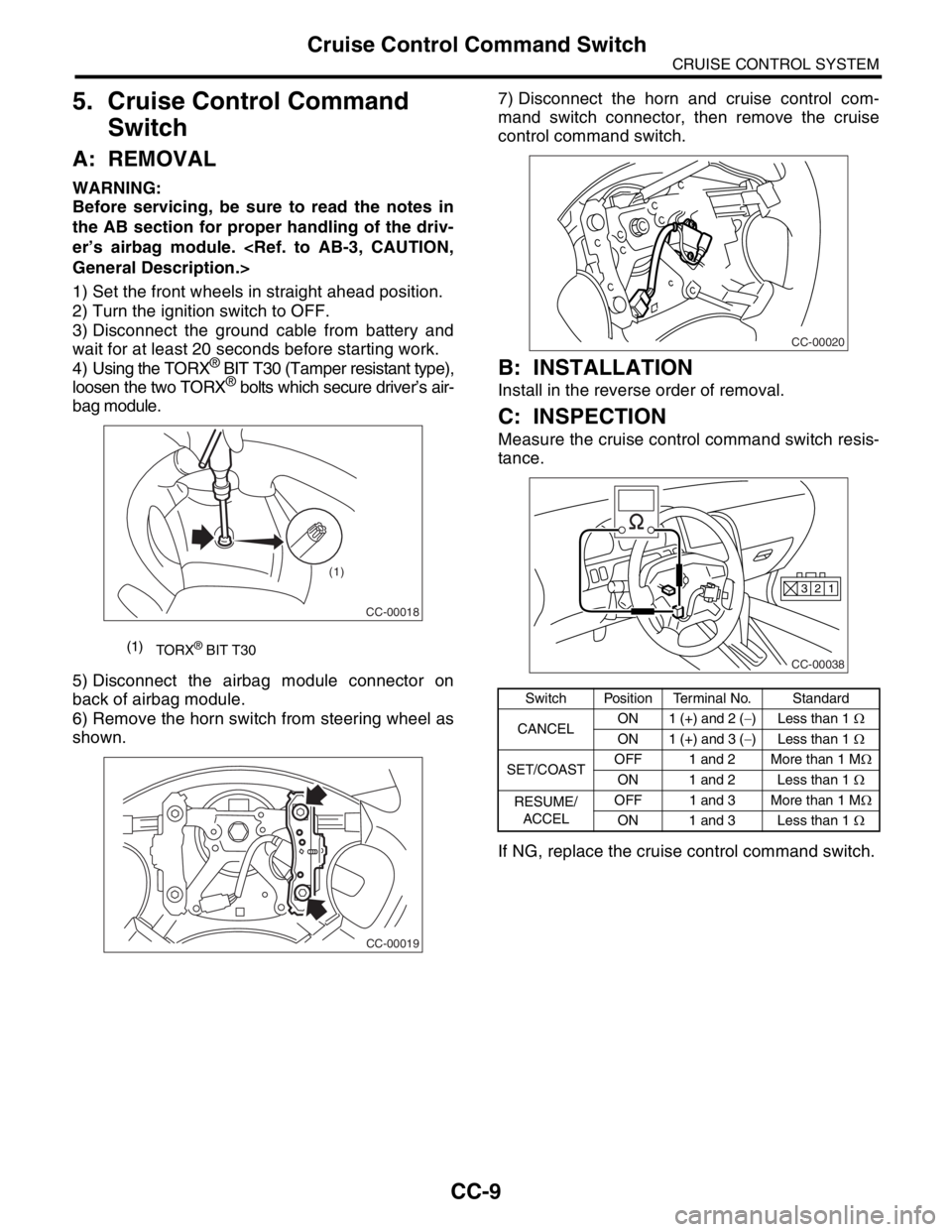
6) Remove the horn switch from steering wheel as
shown.7) Disconnect the horn and cruise control com-
mand switch connector, then remove the cruise
control command switch.
B: INSTALLATION
Install in the reverse order of removal.
C: INSPECTION
Measure the cruise control command switch resis-
tance.
If NG, replace the cruise control command switch.
(1)
TORX® BIT T30
CC-00018
(1)
CC-00019
Switch Position Terminal No. Standard
CANCELON 1 (+) and 2 (−) Less than 1 Ω
ON 1 (+) and 3 (−) Less than 1 Ω
SET/COASTOFF 1 and 2 More than 1 MΩ
ON 1 and 2 Less than 1 Ω
RESUME/
ACCELOFF 1 and 3 More than 1 MΩ
ON 1 and 3 Less than 1 Ω
CC-00020
CC-00038
1 2 3
Page 587 of 2870
CC(H4SO)-19
CRUISE CONTROL SYSTEM (DIAGNOSTIC)
Diagnostic Procedure with Symptom
E: CHECK CRUISE CONTROL COMMAND SWITCH
TROUBLE SYMPTOM:
Cruise control cannot be set. (Cancelled immediately.)
WIRING DIAGRAM:
CC-00040
B94F45B236S1F144
12345678910
11 12 13 14 15 16 17 18 19 20
412365
4
321
BATTERY
CRUISE CONTROL MODULECRUISE CONTROL
COMMAND SWITCH
STEERING
ROLL CONNECTORHORN HORN RELAY HORN SWITCH
RESUME/
ACCEL
SWITCHCANCEL
SWITCHSET/
COAST
SWITCH M/B No.6
B94
F37
B62F45
S1
321
910
B236
13
3 2
11
3245123
8910411 12 13 14 15 16567
F144
F37
RHD
RHD
LHD
LHD
RHD :
:LHD
: LHD MODEL
: RHD MODEL
LHD
RHDRHD LHD
RHD :
:LHD
Page 588 of 2870

CC(H4SO)-20
CRUISE CONTROL SYSTEM (DIAGNOSTIC)
Diagnostic Procedure with Symptom
Step Check Yes No
1 CHECK SET/COAST SWITCH CIRCUIT.
1) Turn the ignition switch to OFF.
2) Disconnect the cruise control module har-
ness connector.
3) Measure the voltage between harness con-
nector terminal and chassis ground when SET/
COAST switch is pressed and not pressed.
Connector & terminal
(B94) No. 10 (+) — Chassis ground (
−):Is the voltage 0 V when the
SET/COAST switch is not
pressed? Is the voltage more
than 10 V when the SET/
COAST switch is pressed?Go to step 2.Go to step 4.
2 CHECK RESUME/ACCEL SWITCH CIRCUIT.
Measure the voltage between harness connec-
tor terminal and chassis ground when
RESUME/ACCEL switch is pressed and not
pressed.
Connector & terminal
(B94) No. 9 (+) — Chassis ground (
−):Is the voltage 0 V when the
RESUME/ACCEL switch is not
pressed? Is the voltage more
than 10 V when the RESUME/
ACCEL switch is pressed?Go to step 3.Go to step 4.
3 CHECK CANCEL SWITCH CIRCUIT.
Measure the voltage between harness connec-
tor terminal and chassis ground when CAN-
CEL switch is pressed and not pressed.
Connector & terminal
(B94) No. 9 (+) — Chassis ground (
−):
(B94) No. 10 (+) — Chassis ground (
−): Is the voltage 0 V when the
CANCEL switch is not
pressed? Is the voltage more
than 10 V when the CANCEL
switch is pressed?Cruise control
command switch
circuit is OK.Go to step 4.
4 CHECK POWER SUPPLY FOR COMMAND
SWITCH.
Check the horn operation.Does the horn sound? Go to step 5. Check the fuse
No. 6 (in main fuse
box).
Check the horn
relay.
COM-3, INSPEC-
TION, Horn Sys-
tem.>
Check the har-
ness for open or
short between
cruise control
command switch
and fuse & relay
box.
5 CHECK CRUISE CONTROL COMMAND
SWITCH.
Remove and check the cruise control com-
mand switch.
Command Switch.>Is the cruise control command
switch OK?Check the harness
between cruise
control command
switch and cruise
control module.Replace the cruise
control command
switch.