CC(H4DOTC 2.5)-16
CRUISE CONTROL SYSTEM (DIAGNOSTIC)
Diagnostic Procedure with Diagnostic Trouble Code (DTC)
8. Diagnostic Procedure with Diagnostic Trouble Code (DTC)
A: DTC 11, 15, 21 AND 24 CRUISE CONTROL COMMAND SWITCH
TROUBLE SYMPTOM:
Cruise control cannot be set. (Cancelled immediately.)
Cruise control cannot be released.
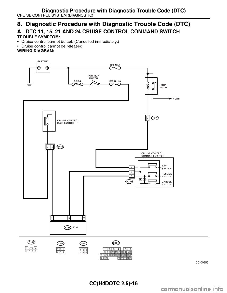
WIRING DIAGRAM:
CC-00256
F37B236
31264531245
B136
9
30 29 28 323120 19 18 22211012
1114
24
34 3327
261612345613
2315
25871735
B136M/B No.6
10113
B2361SET
SWITCH
CANCEL
SWITCHRESUME
SWITCH SBF-4F/B No.18
7
ECM BATTERY
HORN IGNITION
SWITCH
5
CRUISE CONTROL
MAIN SWITCH4
B161
2
3CRUISE CONTROL
COMMAND SWITCHF37HORN
RELAY
B161
12
3456
CC(H4DOTC 2.5)-17
CRUISE CONTROL SYSTEM (DIAGNOSTIC)
Diagnostic Procedure with Diagnostic Trouble Code (DTC)
Step Check Yes No
1 CHECK CRUISE CONTROL MAIN SWITCH
CIRCUIT.
1) Turn the ignition switch to OFF.
2) Disconnect the ECM harness connector.
3) Turn the ignition switch to ON.
4) Measure the voltage between harness con-
nector terminal and chassis ground when the
main switch is pressed and is not pressed.
Connector & terminal
(B136) No. 7 (+) — Chassis ground (
−):Is the voltage 0 V when the
main switch is not pressed? Is
the voltage more than 10 V
when the main switch is
pressed?Go to step 2. Check the fuse
No. 18 (in fuse &
relay box).
Check the har-
ness for open or
short between
cruise control
command switch
and fuse & relay
box. If no malfunc-
tion is found after
checking above,
Go to step 6.
2 CHECK SET/COAST SWITCH CIRCUIT.
1) Turn the ignition switch to OFF.
2) Disconnect the ECM harness connector.
3) Measure the voltage between harness con-
nector terminal and chassis ground when SET/
COAST switch is pressed and not pressed.
Connector & terminal
(B136) No. 11 (+) — Chassis ground (
−):Is the voltage 0 V when SET/
COAST switch is not pressed?
Is the voltage more than 10 V
when SET/COAST switch is
pressed?Go to step 3.Go to step 5.
3 CHECK RESUME/ACCEL SWITCH CIRCUIT.
Measure the voltage between harness connec-
tor terminal and chassis ground when
RESUME/ACCEL switch is pressed and not
pressed.
Connector & terminal
(B136) No. 10 (+) — Chassis ground (
−):Is the voltage 0 V when
RESUME/ACCEL switch is not
pressed? Is the voltage more
than 10 V when RESUME/
ACCEL switch is pressed?Go to step 4.Go to step 5.
4 CHECK CANCEL SWITCH CIRCUIT.
Measure the voltage between harness connec-
tor terminal and chassis ground when CAN-
CEL switch is pressed and not pressed.
Connector & terminal
(B136) No. 10 (+) — Chassis ground (
−):
(B136) No. 11 (+) — Chassis ground (
−): Is the voltage 0 V when CAN-
CEL switch is not pressed? Is
the voltage more than 10 V
when CANCEL switch is
pressed?Cruise control
command switch
circuit is OK.Go to step 5.
5 CHECK POWER SUPPLY FOR COMMAND
SWITCH.
Check the horn operation.Does the horn sound? Go to step 6. Check the fuse
No. 6 (in main fuse
box).
Check the horn
relay.
COM-3, HORN
RELAY, INSPEC-
TION, Horn Sys-
tem.>
Check the har-
ness for open or
short between
cruise control
command switch
and fuse & relay
box.
6 CHECK CRUISE CONTROL COMMAND
SWITCH.
Remove and check the cruise control com-
mand switch.
Command Switch.>Is the cruise control command
switch OK?Check the harness
between cruise
control command
switch and ECM.Replace the cruise
control command
switch.