2004 SUBARU FORESTER wheel alignment
[x] Cancel search: wheel alignmentPage 726 of 2870

PI-3
PRE-DELIVERY INSPECTION
Pre-delivery Inspection
B: PDI PROCEDURE
Follow the procedures shown in the table below.
Static Checks Just After Vehicle Receipt
Step Check point
1. Appearance check (1) If the vehicle is covered with protective coating, visually check the vehicle
body for damage and dents. If the protective coating has been removed,
visually check the body paints for small areas of damage or stains.
(2) Visually check the glass and light lenses for any damage and cracks or
excessive gaps to the body sheet metal.
(3) Visually check the plated parts for any damage.
2. Tire check (1) Check the tires for damage, abnormal conditions, and dents on the
wheels.
(2) Check the tire air pressure.
3. Fuse installation If the vehicle is about to be delivered to the customer, attach a room light
fuse.
4. Connection of air conditioner harness If the vehicle is about to be delivered to the customer, connect the air condi-
tioner harness.
5. Check the doors for lock/unlock and open/close
operations.(1) Using the key, check if the door can be locked and unlocked normally.
(2) Open and close all doors to see that there are no abnormal conditions.
6. Operation check of double lock Check that the double lock operates normally.
7. Operation check of the child safety lock system. Check the child safety lock system operates normally.
8. Check the rear gate for lock/unlock and open/
close operations.(1) Check if the rear gate can be unlocked normally from the emergency
door.
(2) Open and close the rear gate to see that there are no abnormal condi-
tions.
(3) Operate the power door locking switch to check that the rear gate is
locked and unlocked normally.
9. Operation check of fuel lid opener lock release
leverOperate the fuel lid opener to check that the fuel lid is unlocked normally.
10. Accessory check Check that the following accessories are provided:
Owner’s manual
Warranty booklet
Service booklet
Spare key
Jack
Tool set
Spare tire
11. Operation check of hood lock release system Operate the hood lock release lever to check that the hood opens normally.
12. Battery Check the battery for any abnormal conditions such as rust and trace of bat-
tery fluid leaks.
13. Brake fluid Check the fluid amount.
14. Engine oil Check the oil amount.
15. Transmission fluid (1) Check the fluid amount.
(2) For AT, check the front differential oil.
16. AT front differential oil Check the AT front differential oil amount.
17. Coolant Check the coolant amount.
18. Clutch fluid Check the clutch fluid amount.
19. Window washer fluid Check the window washer fluid amount.
20. Hood latch check Check that the hood is closed and latched securely.
21. Keyless entry system Check that the keyless entry system operates normally.
22. Security system Check that the security system operates normally.
23. Seat (1) Check the seat surfaces for smears or dirt.
(2) Check the seat installation conditions and functionality.
24. Seat belt Check the seat belt installation conditions and functionality.
25. Wheel alignment Check that the wheel alignments are properly adjusted.
Page 733 of 2870

PI-10
PRE-DELIVERY INSPECTION
Pre-delivery Inspection
21.KEYLESS ENTRY SYSTEM
Check the keyless entry system operations as fol-
lows:
Fully open all the door windows.
Remove the key from the ignition switch and
close all the doors including rear gate.
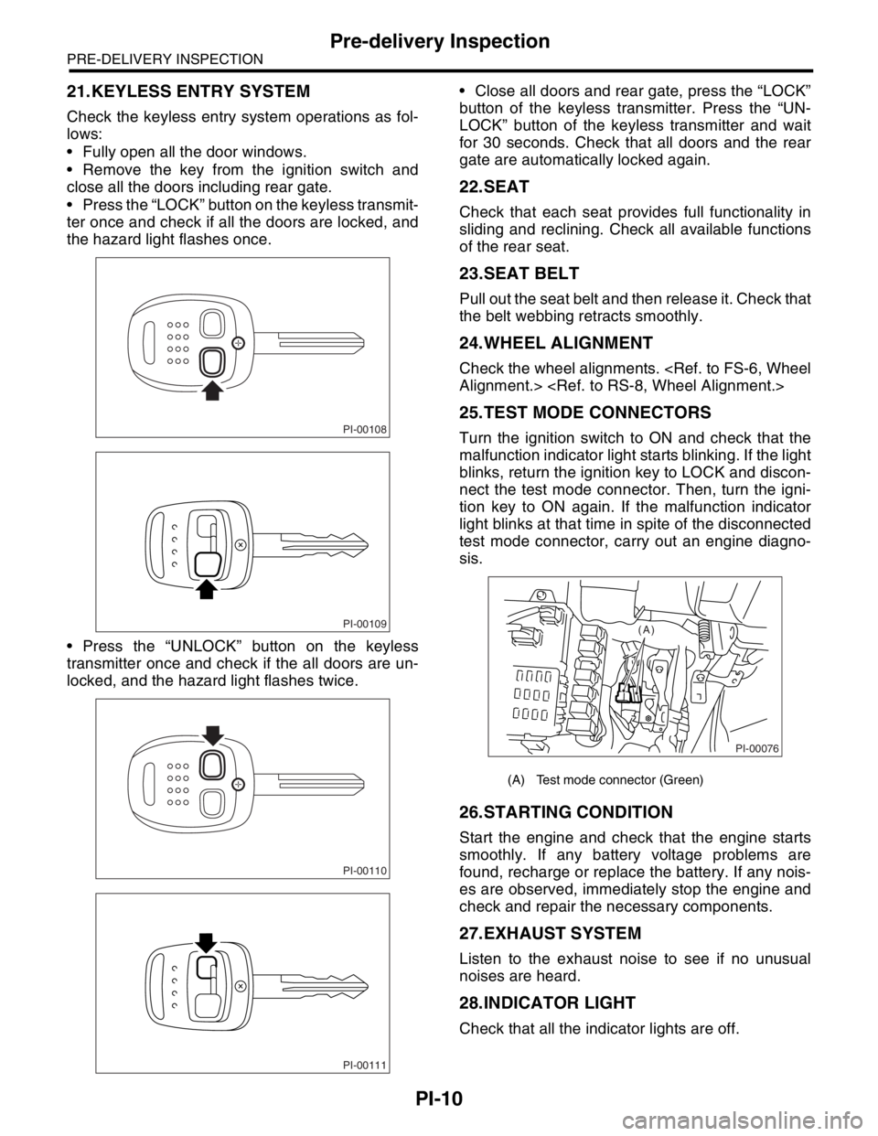
Press the “LOCK” button on the keyless transmit-
ter once and check if all the doors are locked, and
the hazard light flashes once.
Press the “UNLOCK” button on the keyless
transmitter once and check if the all doors are un-
locked, and the hazard light flashes twice. Close all doors and rear gate, press the “LOCK”
button of the keyless transmitter. Press the “UN-
LOCK” button of the keyless transmitter and wait
for 30 seconds. Check that all doors and the rear
gate are automatically locked again.
22.SEAT
Check that each seat provides full functionality in
sliding and reclining. Check all available functions
of the rear seat.
23.SEAT BELT
Pull out the seat belt and then release it. Check that
the belt webbing retracts smoothly.
24.WHEEL ALIGNMENT
Check the wheel alignments.
25.TEST MODE CONNECTORS
Turn the ignition switch to ON and check that the
malfunction indicator light starts blinking. If the light
blinks, return the ignition key to LOCK and discon-
nect the test mode connector. Then, turn the igni-
tion key to ON again. If the malfunction indicator
light blinks at that time in spite of the disconnected
test mode connector, carry out an engine diagno-
sis.
26.STARTING CONDITION
Start the engine and check that the engine starts
smoothly. If any battery voltage problems are
found, recharge or replace the battery. If any nois-
es are observed, immediately stop the engine and
check and repair the necessary components.
27.EXHAUST SYSTEM
Listen to the exhaust noise to see if no unusual
noises are heard.
28.INDICATOR LIGHT
Check that all the indicator lights are off.
PI-00108
PI-00109
PI-00110
PI-00111
(A) Test mode connector (Green)
PI-00076
(A)
Page 773 of 2870

PM-36
PERIODIC MAINTENANCE SERVICE
Suspension
22.Suspension
A: INSPECTION
1. SUSPENSION BALL JOINT
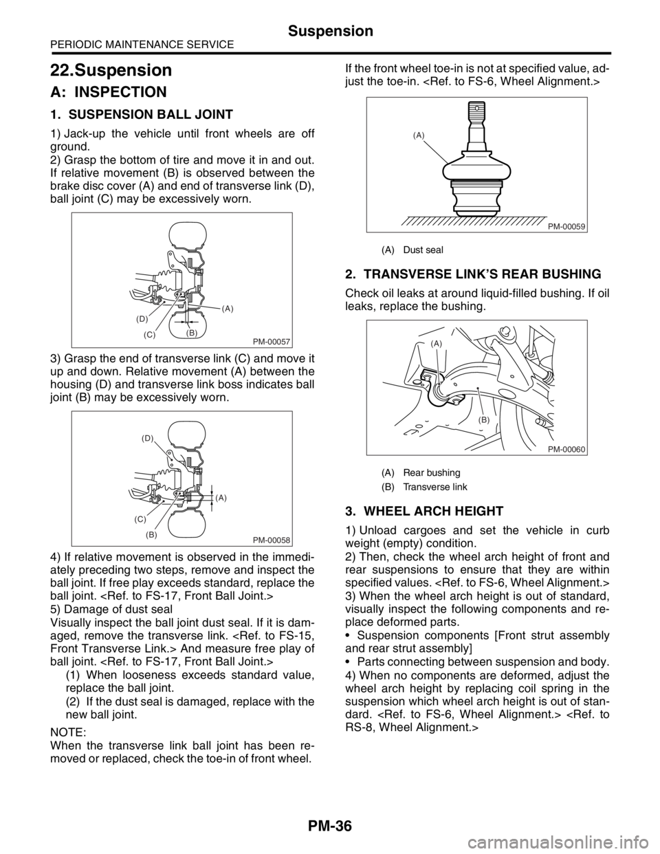
1) Jack-up the vehicle until front wheels are off
ground.
2) Grasp the bottom of tire and move it in and out.
If relative movement (B) is observed between the
brake disc cover (A) and end of transverse link (D),
ball joint (C) may be excessively worn.
3) Grasp the end of transverse link (C) and move it
up and down. Relative movement (A) between the
housing (D) and transverse link boss indicates ball
joint (B) may be excessively worn.
4) If relative movement is observed in the immedi-
ately preceding two steps, remove and inspect the
ball joint. If free play exceeds standard, replace the
ball joint.
5) Damage of dust seal
Visually inspect the ball joint dust seal. If it is dam-
aged, remove the transverse link.
ball joint.
(1) When looseness exceeds standard value,
replace the ball joint.
(2) If the dust seal is damaged, replace with the
new ball joint.
NOTE:
When the transverse link ball joint has been re-
moved or replaced, check the toe-in of front wheel. If the front wheel toe-in is not at specified value, ad-
just the toe-in.
2. TRANSVERSE LINK’S REAR BUSHING
Check oil leaks at around liquid-filled bushing. If oil
leaks, replace the bushing.
3. WHEEL ARCH HEIGHT
1) Unload cargoes and set the vehicle in curb
weight (empty) condition.
2) Then, check the wheel arch height of front and
rear suspensions to ensure that they are within
specified values.
3) When the wheel arch height is out of standard,
visually inspect the following components and re-
place deformed parts.
Suspension components [Front strut assembly
and rear strut assembly]
Parts connecting between suspension and body.
4) When no components are deformed, adjust the
wheel arch height by replacing coil spring in the
suspension which wheel arch height is out of stan-
dard.
PM-00057
(A)
(B)
(C) (D)
PM-00058
(A)
(B) (C)(D)
(A) Dust seal
(A) Rear bushing
(B) Transverse link
PM-00059
(A)
PM-00060
(A)
(B)
Page 774 of 2870

PM-37
PERIODIC MAINTENANCE SERVICE
Suspension
4. WHEEL ALIGNMENT OF FRONT SUS-
PENSION
1) Check the alignment of front suspension to en-
sure that following items conform to standard val-
ues.
Toe-in
Camber angle
Caster angle
Steering angle
2) When the caster angle does not conform to ref-
erence, visually inspect the following components
and replace deformed parts.
Suspension components [Strut assembly, cross-
member, transverse link, etc.]
Body parts to which suspensions are installed.
3) When the toe-in and camber are out of standard
value, adjust them so that they conform to respec-
tive service standard.
ment.>
4) When the right-and-left turning angles of tire are
out of standard, adjust to standard value.
Alignment.>
5. WHEEL ALIGNMENT OF REAR SUS-
PENSION
1) Check the alignment of rear suspension to en-
sure that following items are within standard val-
ues.
Toe-in
Camber angle
Thrust angle
2) When the camber angle does not conform to ref-
erence, visually inspect parts listed below. If defor-
mation is observed, replace the damaged parts.
Suspension components [Shock absorber, front
lateral links, rear lateral links, trailing link, etc.]
Body parts to which suspensions are installed.
3) When the toe-in and thrust angle are out of stan-
dard value, adjust them so that they conform to re-
spective service standard.
ment.>
6. OIL LEAKAGE OF STRUT
Visually inspect the front strut and rear strut for oil
leakage as instructed. If oil leakage reaches under
spring seat lower portion, replace the front strut and
rear strut.
7. TIGHTNESS OF BOLTS AND NUTS
Check the bolts and nuts shown in the figure for
looseness. Retighten the bolts and nuts to speci-
fied torque. If the self-lock nuts and bolts are re-
moved, replace them with new ones.
Front suspension:
Rear suspension:
8. DAMAGE TO SUSPENSION PARTS
Check the following parts and the fastening portion
of the vehicle body for deformation or excessive
rusting which impairs the suspension. Remove the
contaminations on spring seat lower portion with
care because dirt, sand, etc. tend to accumulate on
it. If necessary, replace the damaged parts with
new ones. If minor rust formation, pitting, etc. are
noted, remove the rust and apply remedial anti-cor-
rosion measures.
Front suspension
Transverse link
Crossmember
Strut
Rear suspension
Crossmember
Lateral links
Trailing link
Strut
In the district where salt is sprayed to melt snow
on a road in winter, check suspension parts for
damage caused by rust every 12 months after
lapse of 60 months. Take rust prevention measure
as required.
Page 777 of 2870

PM-40
PERIODIC MAINTENANCE SERVICE
Tire Rotation
25.Tire Rotation
A: INSPECTION
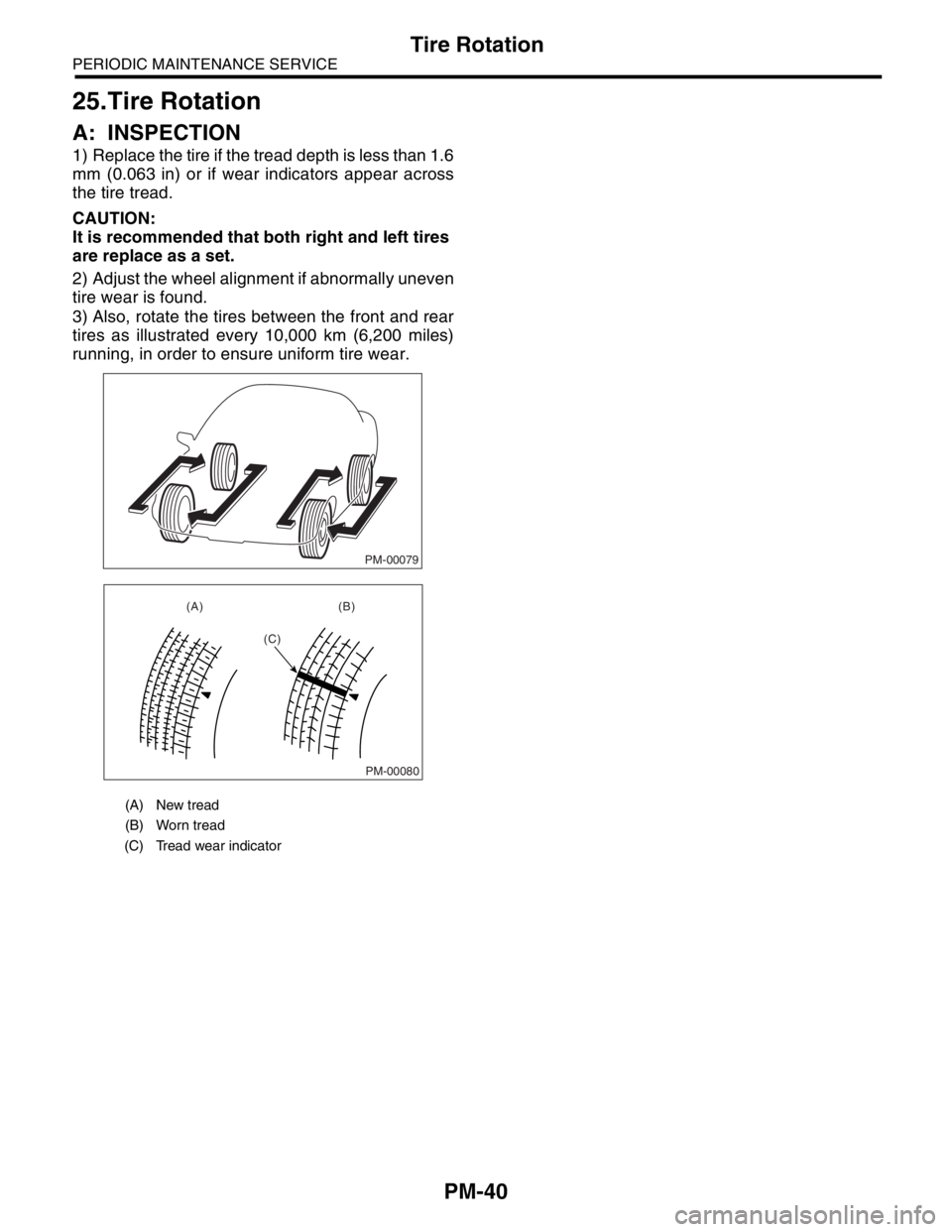
1) Replace the tire if the tread depth is less than 1.6
mm (0.063 in) or if wear indicators appear across
the tire tread.
CAUTION:
It is recommended that both right and left tires
are replace as a set.
2) Adjust the wheel alignment if abnormally uneven
tire wear is found.
3) Also, rotate the tires between the front and rear
tires as illustrated every 10,000 km (6,200 miles)
running, in order to ensure uniform tire wear.
(A) New tread
(B) Worn tread
(C) Tread wear indicator
PM-00079
PM-00080
(A) (B)
(C)