2004 SUBARU FORESTER fuel cap release
[x] Cancel search: fuel cap releasePage 903 of 2870
ME(H4SO)-34
MECHANICAL
Engine Assembly
9. Engine Assembly
A: REMOVAL
1) Set the vehicle on lift arms.
2) Open the front hood fully, and then support with
the front hood stay.
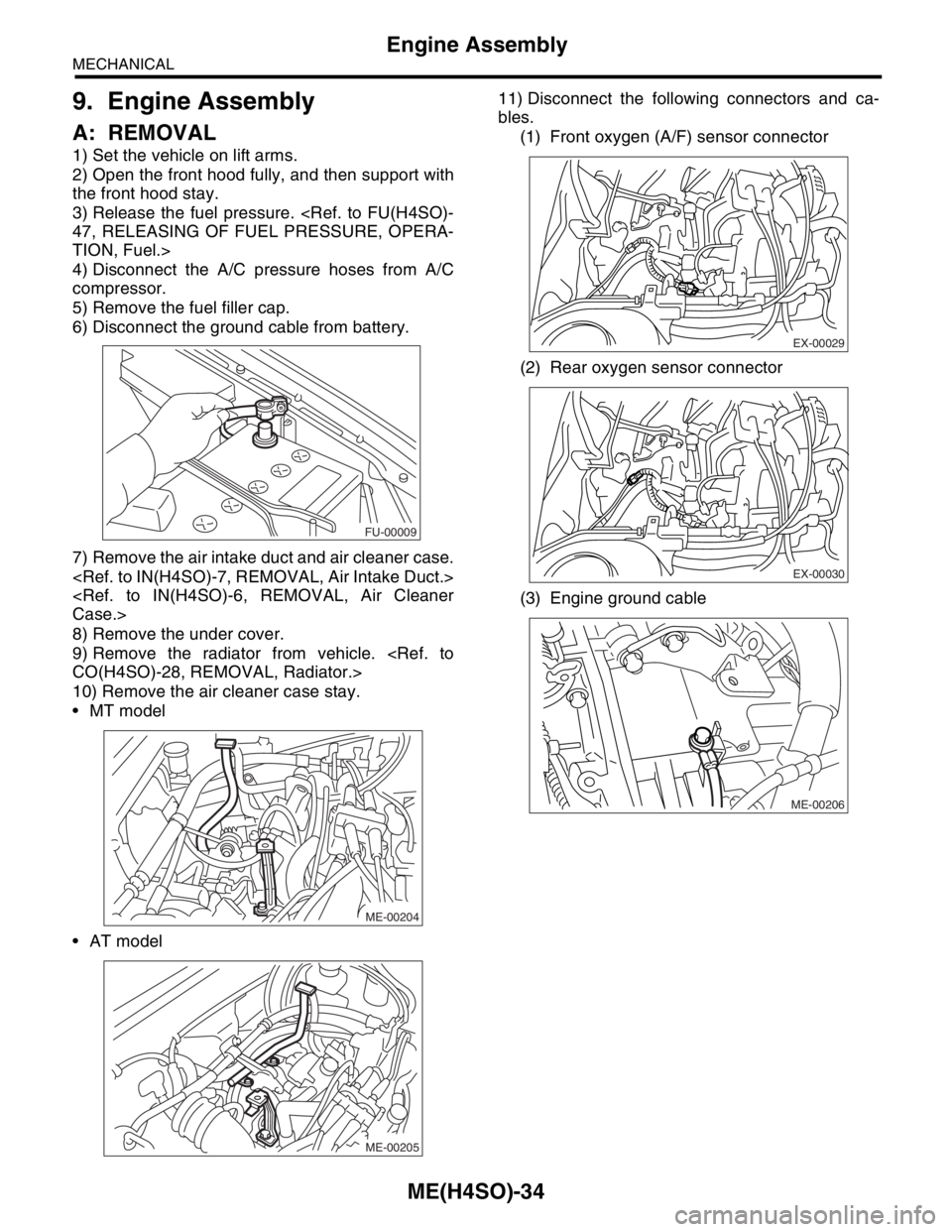
3) Release the fuel pressure.
TION, Fuel.>
4) Disconnect the A/C pressure hoses from A/C
compressor.
5) Remove the fuel filler cap.
6) Disconnect the ground cable from battery.
7) Remove the air intake duct and air cleaner case.
8) Remove the under cover.
9) Remove the radiator from vehicle.
10) Remove the air cleaner case stay.
MT model
AT model11) Disconnect the following connectors and ca-
bles.
(1) Front oxygen (A/F) sensor connector
(2) Rear oxygen sensor connector
(3) Engine ground cable
FU-00009
ME-00204
ME-00205
EX-00029
EX-00030
ME-00206
Page 1105 of 2870
EN(H4SO)-7
ENGINE (DIAGNOSTIC)
General Description
The antenna feeder must be placed as far
apart as possible from the ECM and MFI har-
ness.
Carefully adjust the antenna for correct
matching.
When mounting a large power type radio, pay
special attention to the three items above men-
tioned.
Incorrect installation of the radio may affect
the operation of the ECM.
13) Before disconnecting the fuel hose, disconnect
the fuel pump connector and crank the engine for
more than five seconds to release pressure in the
fuel system. If engine starts during this operation,
run it until it stops.
14) Problems in the electronic-controlled automatic
transmission may be caused by failure of the en-
gine, the electronic control system, the transmis-
sion proper, or by a combination of these. These
three causes must be distinguished clearly when
performing diagnostics.
15) Diagnostics should be conducted by rotating
with simple, easy operations and proceeding to
complicated, difficult operations. The most impor-
tant thing in diagnostics is to understand the cus-
tomer’s complaint, and distinguish between the
three causes.
16) In AT models, do not continue the stall for more
than five seconds. (from closed throttle, fully open
throttle to stall engine speed.)
17) On the model with ABS, when performing driv-
ing test in jacked-up or lifted-up position, some-
times the warning light may be lit, but this is not a
malfunction of the system. The reason for this is the
speed difference between the front and rear
wheels. After diagnosis of engine control system,
perform the ABS memory clearance procedure of
self-diagnosis function.
B: INSPECTION
Before performing diagnostics, check the following
items which might affect engine problems:
1. BATTERY
1) Measure battery voltage and specific gravity of
electrolyte.
Standard voltage: 12 V
Specific gravity: Above 1.260
2) Check the condition of the main and other fuses,
and harnesses and connectors. Also check for
proper grounding.
2. ENGINE GROUND
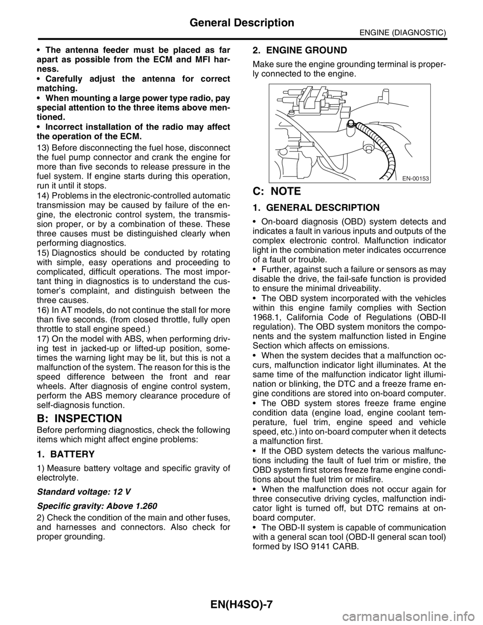
Make sure the engine grounding terminal is proper-
ly connected to the engine.
C: NOTE
1. GENERAL DESCRIPTION
On-board diagnosis (OBD) system detects and
indicates a fault in various inputs and outputs of the
complex electronic control. Malfunction indicator
light in the combination meter indicates occurrence
of a fault or trouble.
Further, against such a failure or sensors as may
disable the drive, the fail-safe function is provided
to ensure the minimal driveability.
The OBD system incorporated with the vehicles
within this engine family complies with Section
1968.1, California Code of Regulations (OBD-II
regulation). The OBD system monitors the compo-
nents and the system malfunction listed in Engine
Section which affects on emissions.
When the system decides that a malfunction oc-
curs, malfunction indicator light illuminates. At the
same time of the malfunction indicator light illumi-
nation or blinking, the DTC and a freeze frame en-
gine conditions are stored into on-board computer.
The OBD system stores freeze frame engine
condition data (engine load, engine coolant tem-
perature, fuel trim, engine speed and vehicle
speed, etc.) into on-board computer when it detects
a malfunction first.
If the OBD system detects the various malfunc-
tions including the fault of fuel trim or misfire, the
OBD system first stores freeze frame engine condi-
tions about the fuel trim or misfire.
When the malfunction does not occur again for
three consecutive driving cycles, malfunction indi-
cator light is turned off, but DTC remains at on-
board computer.
The OBD-II system is capable of communication
with a general scan tool (OBD-II general scan tool)
formed by ISO 9141 CARB.
EN-00153
Page 1237 of 2870

EN(H4SO)-139
ENGINE (DIAGNOSTIC)
Diagnostic Procedure with Diagnostic Trouble Code (DTC)
AB:DTC P0172 SYSTEM TOO RICH (BANK 1)
DTC DETECTING CONDITION:
Two consecutive driving cycles with fault
TROUBLE SYMPTOM:
Erroneous idling
Engine stalls.
Poor driving performance
CAUTION:
After repair or replacement of faulty parts, conduct Clear Memory Mode
Step Check Yes No
1 CHECK EXHAUST SYSTEM.Are there holes or loose bolts
on exhaust system?Repair exhaust
system.Go to step 2.
2 CHECK EGR VALVE.Is the EGR valve stuck? Replace the EGR
valve.Go to step 3.
3 CHECK AIR INTAKE SYSTEM.Are there holes, loose bolts or
disconnection of hose on air
intake system?Repair air intake
system.Go to step 4.
4 CHECK PURGE CONTROL SOLENOID
VALVE.Is the purge control solenoid
valve stuck?Replace the purge
control solenoid
valve.Go to step 5.
5 CHECK PCV VALVE.Is the PCV valve stuck? Replace the PCV
valve.Go to step 6.
6 CHECK FUEL PRESSURE.
Warning:
Place “NO FIRE” signs near the working
area.
Be careful not to spill fuel.
1) Release the fuel pressure.
(1) Disconnect the connector from fuel
pump relay.
(2) Start the engine and run it until it stalls.
(3) After the engine stalls, crank it for five
more seconds.
(4) Turn the ignition switch to OFF.
2) Connect the connector to fuel pump relay.
3) Disconnect the fuel delivery hose, and con-
nect the fuel pressure gauge.
4) Install the fuel filler cap.
5) Start the engine and idle while gear posi-
tion is neutral.
6) Measure the fuel pressure while discon-
necting pressure regulator vacuum hose from
intake manifold.
Warning:
Release fuel pressure before removing the
fuel pressure gauge.
NOTE:
If fuel pressure does not increase, squeeze fuel
return hose 2 to 3 times, then measure fuel
pressure again.Is measured value 284 — 314
kPa (2.9 — 3.2 kg/cm
2, 41 —
46 psi)?Go to step 7.Repair the follow-
ing items.
Fuel pressure is
too high:
Clogged fuel
return line or
bent hose
Fuel pressure is
too low:
Improper fuel
pump discharge
Clogged fuel
supply line
Page 1369 of 2870
FU(H4DOTC)-14
FUEL INJECTION (FUEL SYSTEM)
Intake Manifold
3. Intake Manifold
A: REMOVAL
1) Release the fuel pressure.
TION, Fuel.>
2) Open the fuel filler flap lid and remove the fuel
filler cap.
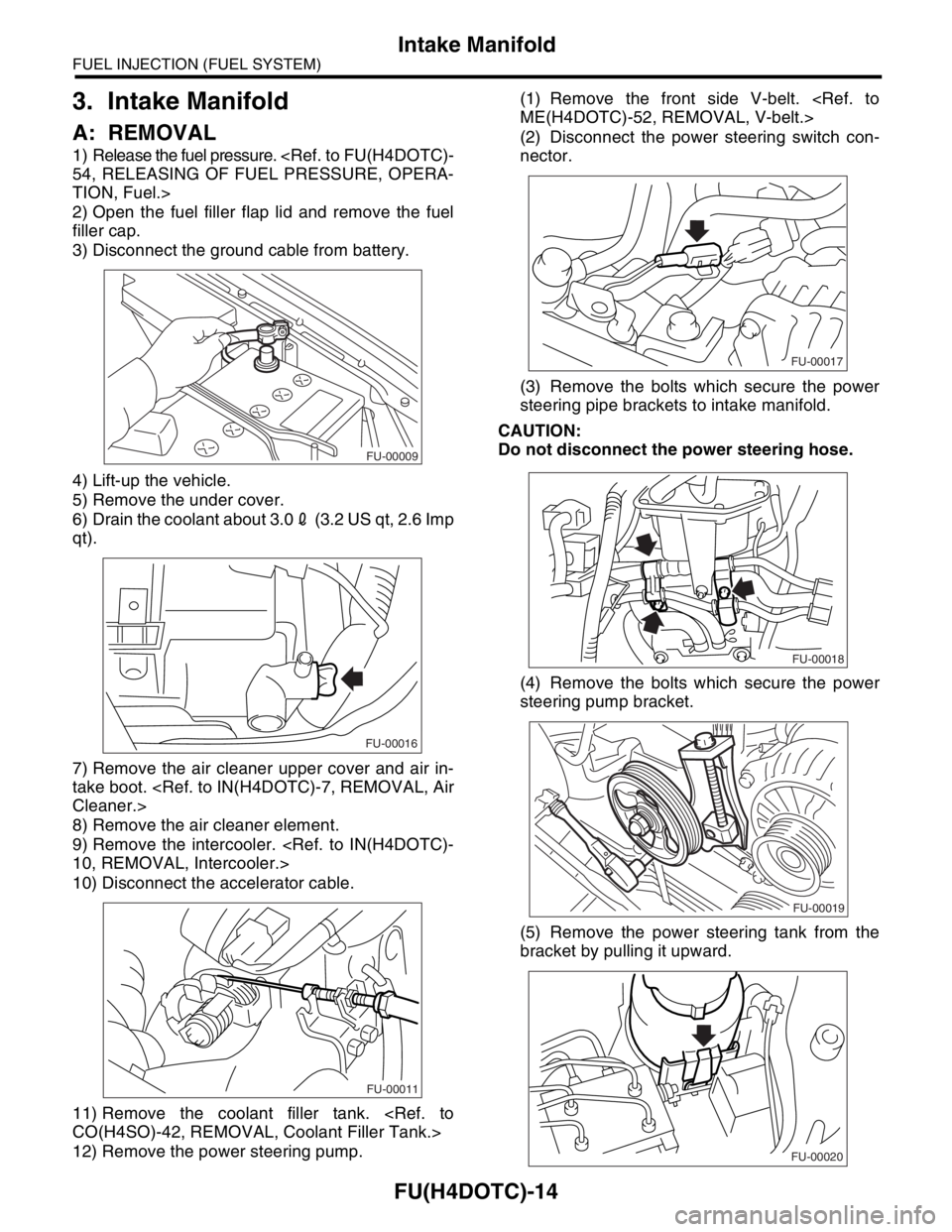
3) Disconnect the ground cable from battery.
4) Lift-up the vehicle.
5) Remove the under cover.
6) Drain the coolant about 3.02 (3.2 US qt, 2.6 Imp
qt).
7) Remove the air cleaner upper cover and air in-
take boot.
8) Remove the air cleaner element.
9) Remove the intercooler.
10) Disconnect the accelerator cable.
11) Remove the coolant filler tank.
12) Remove the power steering pump.(1) Remove the front side V-belt.
(2) Disconnect the power steering switch con-
nector.
(3) Remove the bolts which secure the power
steering pipe brackets to intake manifold.
CAUTION:
Do not disconnect the power steering hose.
(4) Remove the bolts which secure the power
steering pump bracket.
(5) Remove the power steering tank from the
bracket by pulling it upward.
FU-00009
FU-00016
FU-00011
FU-00017
FU-00018
FU-00019
FU-00020
Page 1393 of 2870
FU(H4DOTC)-38
FUEL INJECTION (FUEL SYSTEM)
Fuel Injector
13.Fuel Injector
A: REMOVAL
1. RH SIDE
1) Release the fuel pressure.
TION, Fuel.>
2) Open the fuel filler flap lid and remove the fuel
filler cap.
3) Disconnect the ground cable from battery.
4) Remove the intake manifold.
5) Remove the fuel pipe protector RH.
NOTE:
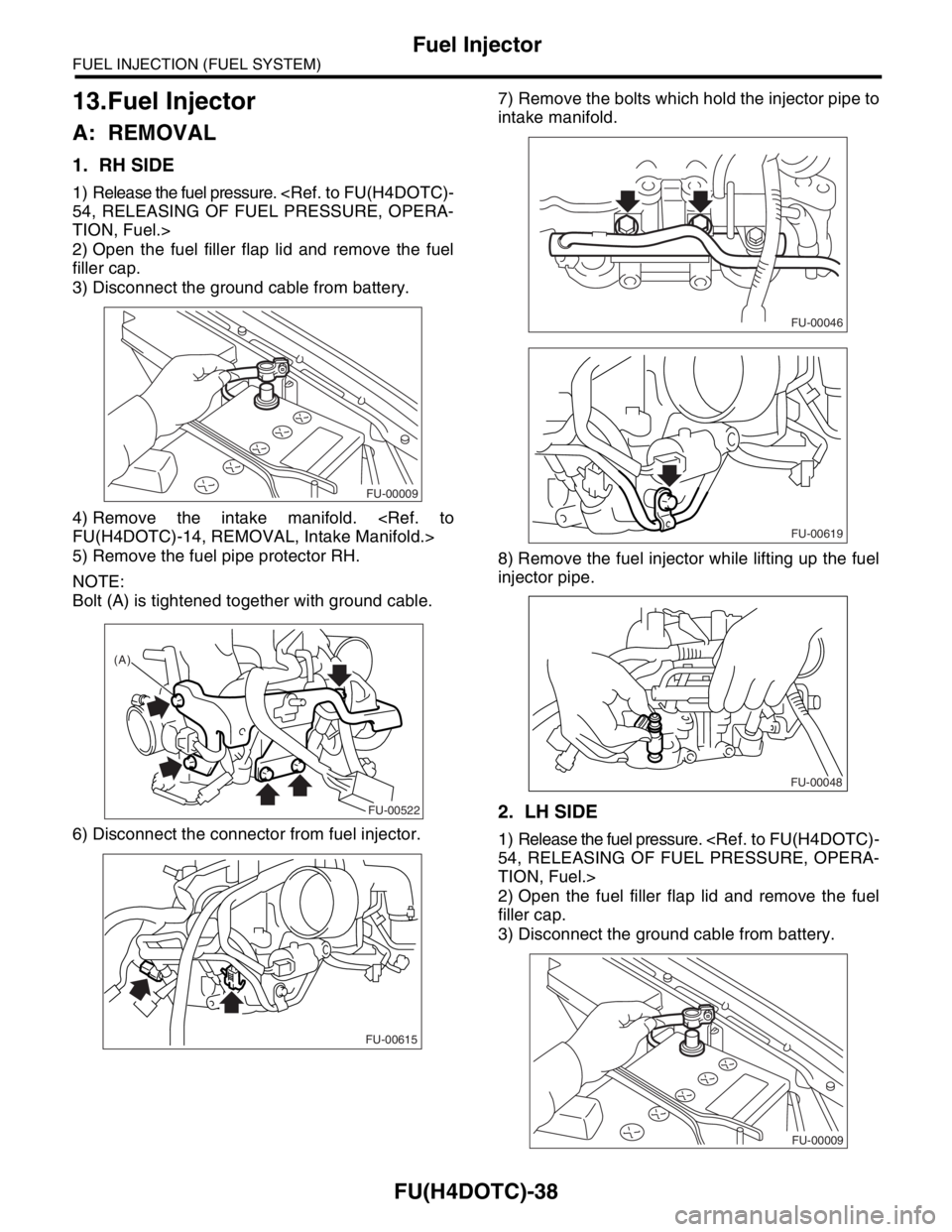
Bolt (A) is tightened together with ground cable.
6) Disconnect the connector from fuel injector.7) Remove the bolts which hold the injector pipe to
intake manifold.
8) Remove the fuel injector while lifting up the fuel
injector pipe.
2. LH SIDE
1) Release the fuel pressure.
TION, Fuel.>
2) Open the fuel filler flap lid and remove the fuel
filler cap.
3) Disconnect the ground cable from battery.
FU-00009
FU-00522
(A)
FU-00615
FU-00046
FU-00619
FU-00048
FU-00009
Page 1397 of 2870
FU(H4DOTC)-42
FUEL INJECTION (FUEL SYSTEM)
Tumble Generator Valve Assembly
14.Tumble Generator Valve As-
sembly
A: REMOVAL
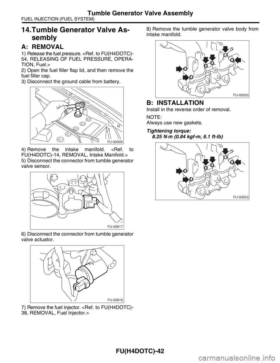
1) Release the fuel pressure.
TION, Fuel.>
2) Open the fuel filler flap lid, and then remove the
fuel filler cap.
3) Disconnect the ground cable from battery.
4) Remove the intake manifold.
5) Disconnect the connector from tumble generator
valve sensor.
6) Disconnect the connector from tumble generator
valve actuator.
7) Remove the fuel injector.
intake manifold.
B: INSTALLATION
Install in the reverse order of removal.
NOTE:
Always use new gaskets.
Tightening torque:
8.25 N
⋅m (0.84 kgf-m, 6.1 ft-lb)
FU-00009
FU-00617
FU-00616
FU-00053
FU-00053
Page 1398 of 2870
FU(H4DOTC)-43
FUEL INJECTION (FUEL SYSTEM)
Tumble Generator Valve Actuator
15.Tumble Generator Valve Ac-
tuator
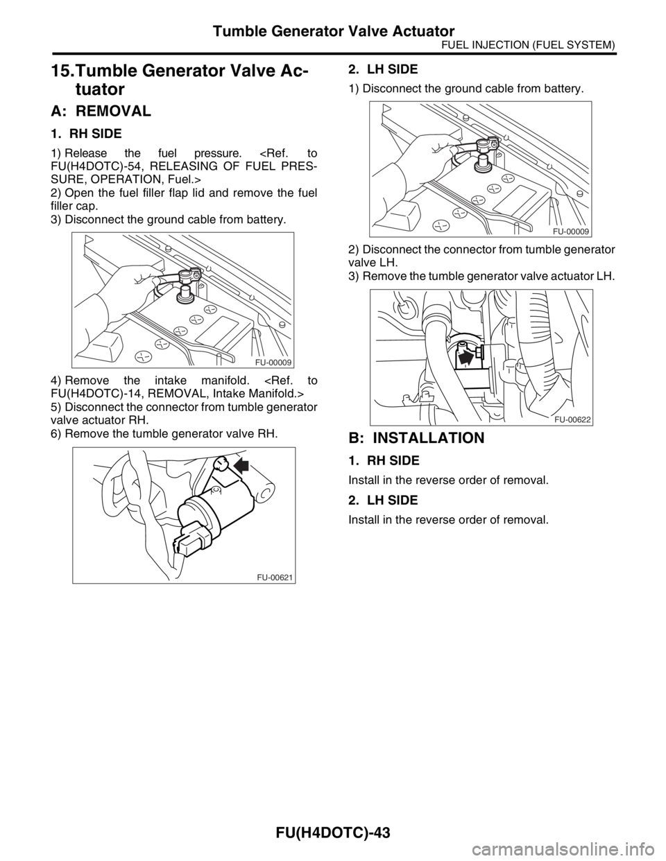
A: REMOVAL
1. RH SIDE
1) Release the fuel pressure.
SURE, OPERATION, Fuel.>
2) Open the fuel filler flap lid and remove the fuel
filler cap.
3) Disconnect the ground cable from battery.
4) Remove the intake manifold.
5) Disconnect the connector from tumble generator
valve actuator RH.
6) Remove the tumble generator valve RH.
2. LH SIDE
1) Disconnect the ground cable from battery.
2) Disconnect the connector from tumble generator
valve LH.
3) Remove the tumble generator valve actuator LH.
B: INSTALLATION
1. RH SIDE
Install in the reverse order of removal.
2. LH SIDE
Install in the reverse order of removal.
FU-00009
FU-00621
FU-00009
FU-00622
Page 1413 of 2870
FU(H4DOTC)-58
FUEL INJECTION (FUEL SYSTEM)
Fuel Filler Pipe
26.Fuel Filler Pipe
A: REMOVAL
WARNING:
Place “NO FIRE” signs near working area.
Be careful not to spill fuel on floor.
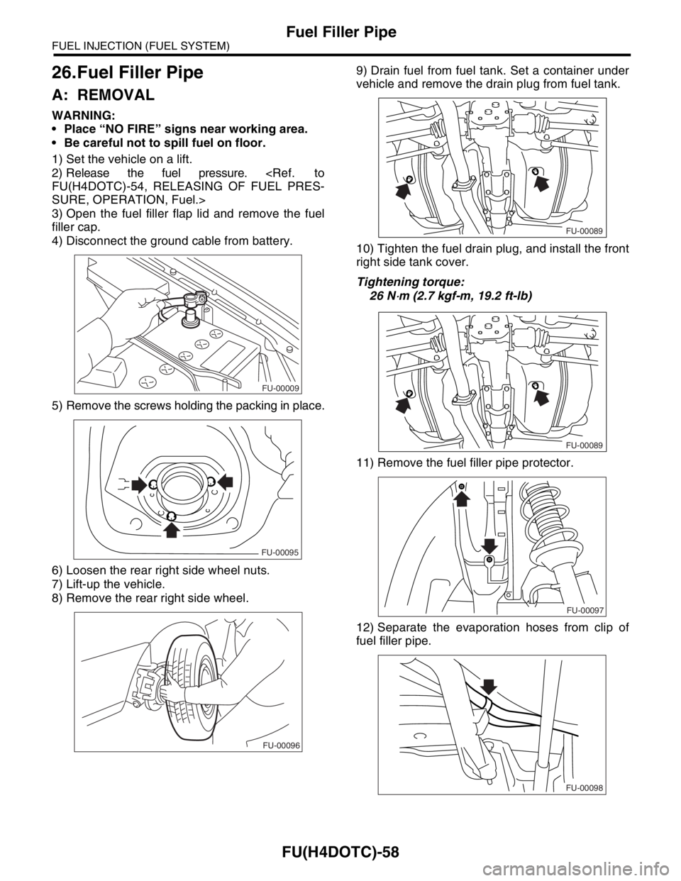
1) Set the vehicle on a lift.
2) Release the fuel pressure.
SURE, OPERATION, Fuel.>
3) Open the fuel filler flap lid and remove the fuel
filler cap.
4) Disconnect the ground cable from battery.
5) Remove the screws holding the packing in place.
6) Loosen the rear right side wheel nuts.
7) Lift-up the vehicle.
8) Remove the rear right side wheel.9) Drain fuel from fuel tank. Set a container under
vehicle and remove the drain plug from fuel tank.
10) Tighten the fuel drain plug, and install the front
right side tank cover.
Tightening torque:
26 N
⋅m (2.7 kgf-m, 19.2 ft-lb)
11) Remove the fuel filler pipe protector.
12) Separate the evaporation hoses from clip of
fuel filler pipe.
FU-00009
FU-00095
FU-00096
FU-00089
FU-00089
FU-00097
FU-00098