2004 SUBARU FORESTER Engine mount
[x] Cancel search: Engine mountPage 967 of 2870

ME(H4SO)-96
MECHANICAL
Engine Noise
23.Engine Noise
A: INSPECTION
NOTE*:
When disconnecting fuel injector connector, the malfunction indicator light illuminates and DTC is stored in ECM memory.
Therefore, carry out the clear memory mode
Regular clicking soundSound increases as engine
speed increases. Valve mechanism is defective.
Incorrect valve clearance
Worn valve rocker
Worn camshaft
Broken valve spring
Heavy and dull clankOil pressure is low. Worn crankshaft main bearing
Worn connecting rod bearing (big end)
Oil pressure is normal. Loose flywheel mounting bolts
Damaged engine mounting
High-pitched clank (Spark
knock)Sound is noticeable when
accelerating with an overload. Ignition timing advanced
Accumulation of carbon inside combustion chamber
Wrong spark plug
Improper gasoline
Clank when engine speed is
medium (1,000 to 2,000 rpm).Sound is reduced when fuel
injector connector of noisy cyl-
inder is disconnected.
(NOTE*) Worn crankshaft main bearing
Worn bearing at crankshaft end of connecting rod
Knocking sound when engine
is operating under idling speed
and engine is warmSound is reduced when fuel
injector connector of noisy cyl-
inder is disconnected.
(NOTE*) Worn cylinder liner and piston ring
Broken or stuck piston ring
Worn piston pin and hole at piston end of connecting rod
Sound is not reduced if each
fuel injector connector is dis-
connected in turn. (NOTE*) Unusually worn valve lifter
Worn cam gear
Worn camshaft journal bore in crankcase
Squeaky sound — Insufficient generator lubrication
Rubbing sound — Defective generator brush and rotor contact
Gear scream when starting
engine— Defective ignition starter switch
Worn gear and starter pinion
Sound like polishing glass with
a dry cloth— Loose drive belt
Defective water pump shaft
Hissing sound — Loss of compression
Air leakage in air intake system, hoses, connections or mani-
folds
Timing belt noise — Loose timing belt
Belt contacting case/adjacent part
Valve tappet noise — Incorrect valve clearance
Page 1003 of 2870
CO(H4SO)-20
COOLING
Engine Coolant
B: INSPECTION
1. RELATIONSHIP OF SUBARU COOLANT
CONCENTRATION AND FREEZING TEM-
PERATURE
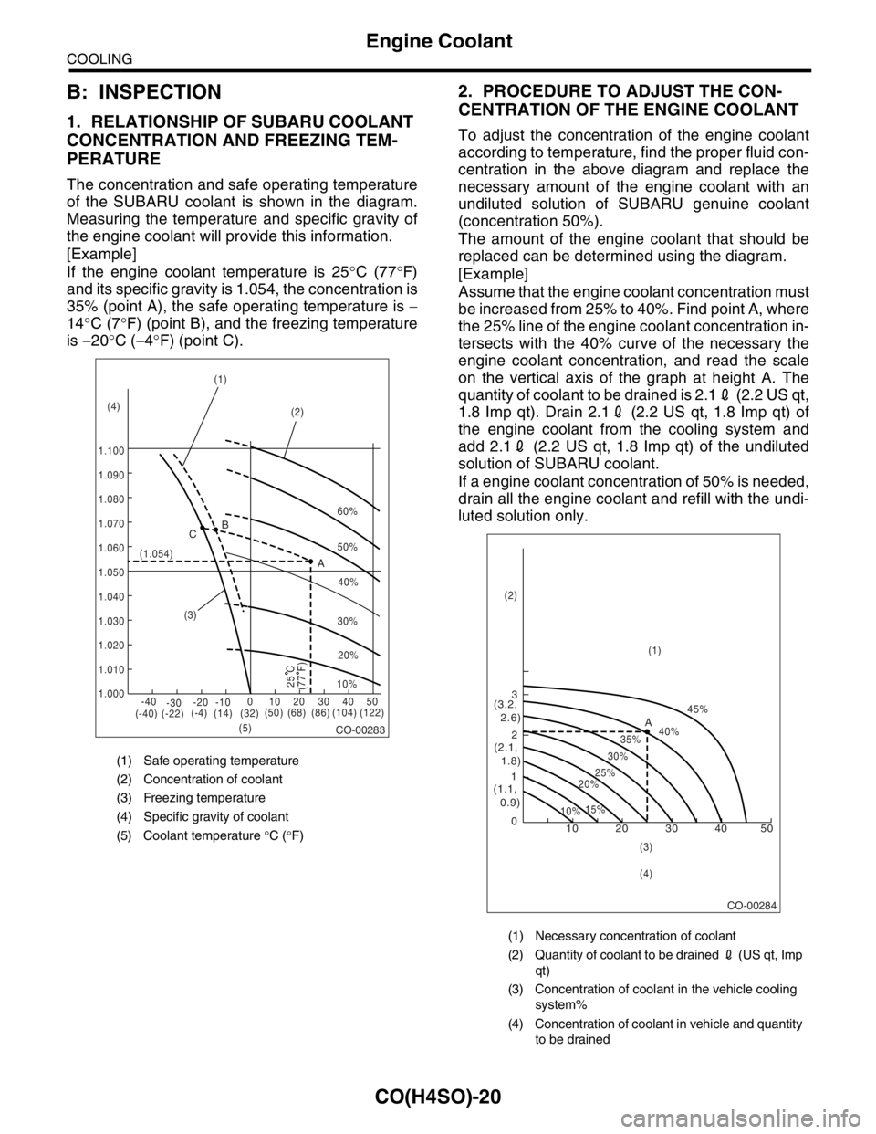
The concentration and safe operating temperature
of the SUBARU coolant is shown in the diagram.
Measuring the temperature and specific gravity of
the engine coolant will provide this information.
[Example]
If the engine coolant temperature is 25°C (77°F)
and its specific gravity is 1.054, the concentration is
35% (point A), the safe operating temperature is −
14°C (7°F) (point B), and the freezing temperature
is −20°C (−4°F) (point C).
2. PROCEDURE TO ADJUST THE CON-
CENTRATION OF THE ENGINE COOLANT
To adjust the concentration of the engine coolant
according to temperature, find the proper fluid con-
centration in the above diagram and replace the
necessary amount of the engine coolant with an
undiluted solution of SUBARU genuine coolant
(concentration 50%).
The amount of the engine coolant that should be
replaced can be determined using the diagram.
[Example]
Assume that the engine coolant concentration must
be increased from 25% to 40%. Find point A, where
the 25% line of the engine coolant concentration in-
tersects with the 40% curve of the necessary the
engine coolant concentration, and read the scale
on the vertical axis of the graph at height A. The
quantity of coolant to be drained is 2.12 (2.2 US qt,
1.8 Imp qt). Drain 2.12 (2.2 US qt, 1.8 Imp qt) of
the engine coolant from the cooling system and
add 2.12 (2.2 US qt, 1.8 Imp qt) of the undiluted
solution of SUBARU coolant.
If a engine coolant concentration of 50% is needed,
drain all the engine coolant and refill with the undi-
luted solution only.
(1) Safe operating temperature
(2) Concentration of coolant
(3) Freezing temperature
(4) Specific gravity of coolant
(5) Coolant temperature °C (°F)
CO-00283
60%
(1.054)
1.000 1.010 1.020
1.030
1.040
1.050
1.060
1.070 1.080 1.090
1.100(1)
(2)
(3)
(5) (4)B
A C
-40
(-40) (-22)(-4)
(14)(32)(50) (68) (86) (104) (122) -30-20 -1001020304050
(77 F)
50%
40%
30%
20%
25 C10%
(1) Necessary concentration of coolant
(2) Quantity of coolant to be drained 2 (US qt, Imp
qt)
(3) Concentration of coolant in the vehicle cooling
system%
(4) Concentration of coolant in vehicle and quantity
to be drained
CO-00284
10 0 12 3
(1.1,
0.9)(2.1,
1.8) (3.2,
2.6)
10%15%25%
20%30%35%40%45%
A
20 30 40 50
(1) (2)
(3)
(4)
Page 1018 of 2870
CO(H4SO)-35
COOLING
Radiator Main Fan and Fan Motor
8. Radiator Main Fan and Fan
Motor
A: REMOVAL
1. NON-TURBO MODEL
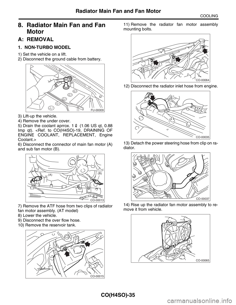
1) Set the vehicle on a lift.
2) Disconnect the ground cable from battery.
3) Lift-up the vehicle.
4) Remove the under cover.
5) Drain the coolant aprrox. 12 (1.06 US qt, 0.88
Imp qt).
Coolant.>
6) Disconnect the connector of main fan motor (A)
and sub fan motor (B).
7) Remove the ATF hose from two clips of radiator
fan motor assembly. (AT model)
8) Lower the vehicle.
9) Disconnect the over flow hose.
10) Remove the reservoir tank.11) Remove the radiator fan motor assembly
mounting bolts.
12) Disconnect the radiator inlet hose from engine.
13) Detach the power steering hose from clip on ra-
diator.
14) Rise up the radiator fan motor assembly to re-
move it from vehicle.
FU-00009
CO-00013
(A)(B)
CO-00015
CO-00064
CO-00035
CO-00037
CO-00065
Page 1022 of 2870
CO(H4SO)-39
COOLING
Radiator Main Fan and Fan Motor
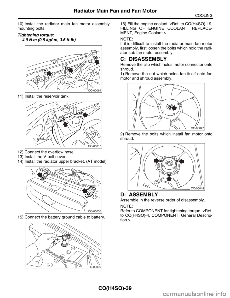
10) Install the radiator main fan motor assembly
mounting bolts.
Tightening torque:
4.9 N
⋅m (0.5 kgf-m, 3.6 ft-lb)
11) Install the reservoir tank.
12) Connect the overflow hose.
13) Install the V-belt cover.
14) Install the radiator upper bracket. (AT model)
15) Connect the battery ground cable to battery.16) Fill the engine coolant.
MENT, Engine Coolant.>
NOTE:
If it is difficult to install the radiator main fan motor
assembly, first loosen the bolts which hold the radi-
ator sub fan motor assembly.
C: DISASSEMBLY
Remove the clip which holds motor connector onto
shroud.
1) Remove the nut which holds fan itself onto fan
motor and shroud assembly.
2) Remove the bolts which install fan motor onto
shroud.
D: ASSEMBLY
Assemble in the reverse order of disassembly.
NOTE:
Refer to COMPONENT for tightening torque.
tion.>
CO-00064
CO-00015
CO-00036
FU-00009
CO-00047
CO-00048
Page 1088 of 2870
SC(H4SO)-13
STARTING/CHARGING SYSTEM
Starter
7. PINION GAP
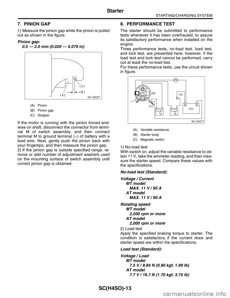
1) Measure the pinion gap while the pinion is pulled
out as shown in the figure.
Pinion gap:
0.5 — 2.0 mm (0.020 — 0.079 in)
If the motor is running with the pinion forced end-
wise on shaft, disconnect the connector from termi-
nal M of switch assembly, and then connect
terminal M to ground terminal (−) of battery with a
lead wire. Next, gently push the pinion back with
your fingertips, and then measure the pinion gap.
2) If the pinion gap is outside specified range, re-
move or add number of adjustment washers used
on the mounting surface of switch assembly until
correct pinion gap is obtained.
8. PERFORMANCE TEST
The starter should be submitted to performance
tests whenever it has been overhauled, to assure
its satisfactory performance when installed on the
engine.
Three performance tests, no-load test, load test,
and lock test, are presented here; however, if the
load test and lock test cannot be performed, carry
out at least the no-load test.
For these performance tests, use the circuit shown
in figure.
1) No-load test
With switch on, adjust the variable resistance to ob-
tain 11 V, take the ammeter reading, and then mea-
sure the starter speed. Compare these values with
the specifications.
No-load test (Standard):
Voltage / Current
MT model
MAX. 11 V / 95 A
AT model
MAX. 11 V / 90 A
Rotating speed
MT model
2,500 rpm or more
AT model
2,000 rpm or more
2) Load test
Apply the specified braking torque to starter. The
condition is satisfactory if the current draw and
starter speed are within the specifications.
Load test (Standard):
Voltage / Load
MT model
7.5 V / 8.84 N (0.90 kgf, 1.99 lb)
AT model
7.7 V / 16.7 N (1.70 kgf, 3.75 lb)
(A) Pinion
(B) Pinion gap
(C) Stopper
SC-00027
(A) Variable resistance
(B) Starter body
(C) Magnetic switch
SC-00077
(A) (B)
(C)
12V +
AV
BS
M
Page 1104 of 2870
EN(H4SO)-6
ENGINE (DIAGNOSTIC)
General Description
3. General Description
A: CAUTION
1) Airbag system wiring harness is routed near the
ECM, main relay and fuel pump relay.
CAUTION:
All air bag system wiring harnesses and con-
nectors are yellow. Do not use the electrical
test equipment on these circuits.
Be careful not to damage the Airbag system
wiring harness when servicing the ECM, TCM,
main relay and fuel pump relay.
2) Never connect the battery in reverse polarity.
The ECM will be destroyed immediately.
The fuel injector and other part will be damaged.
3) Do not disconnect the battery terminals while the
engine is running.
A large counter electromotive force will be generat-
ed in the generator, and this voltage may damage
electronic parts such as ECM, etc.
4) Before disconnecting the connectors of each
sensor and the ECM, be sure to turn the ignition
switch to OFF.
5) Poor contact has been identified as a primary
cause of this problem. Measure the voltage or re-
sistance of individual sensor or all electrical control
modules using a tapered pin with a diameter of less
than 0.64 mm (0.025 in). Do not insert the pin more
than 5 mm (0.20 in) into the part.
6) Remove the ECM from the located position after
disconnecting two cables on battery.
Otherwise, the ECM may be damaged.
CAUTION:
When replacing the ECM, be careful not to use
the wrong spec. ECM to avoid any damage on
the fuel injection system.
7) Connectors to each sensor in the engine com-
partment and the harness connectors on the en-
gine side and body side are all designed to be
waterproof. However, it is still necessary to take
care not to allow water to get into the connectors
when washing the vehicle, or when servicing the
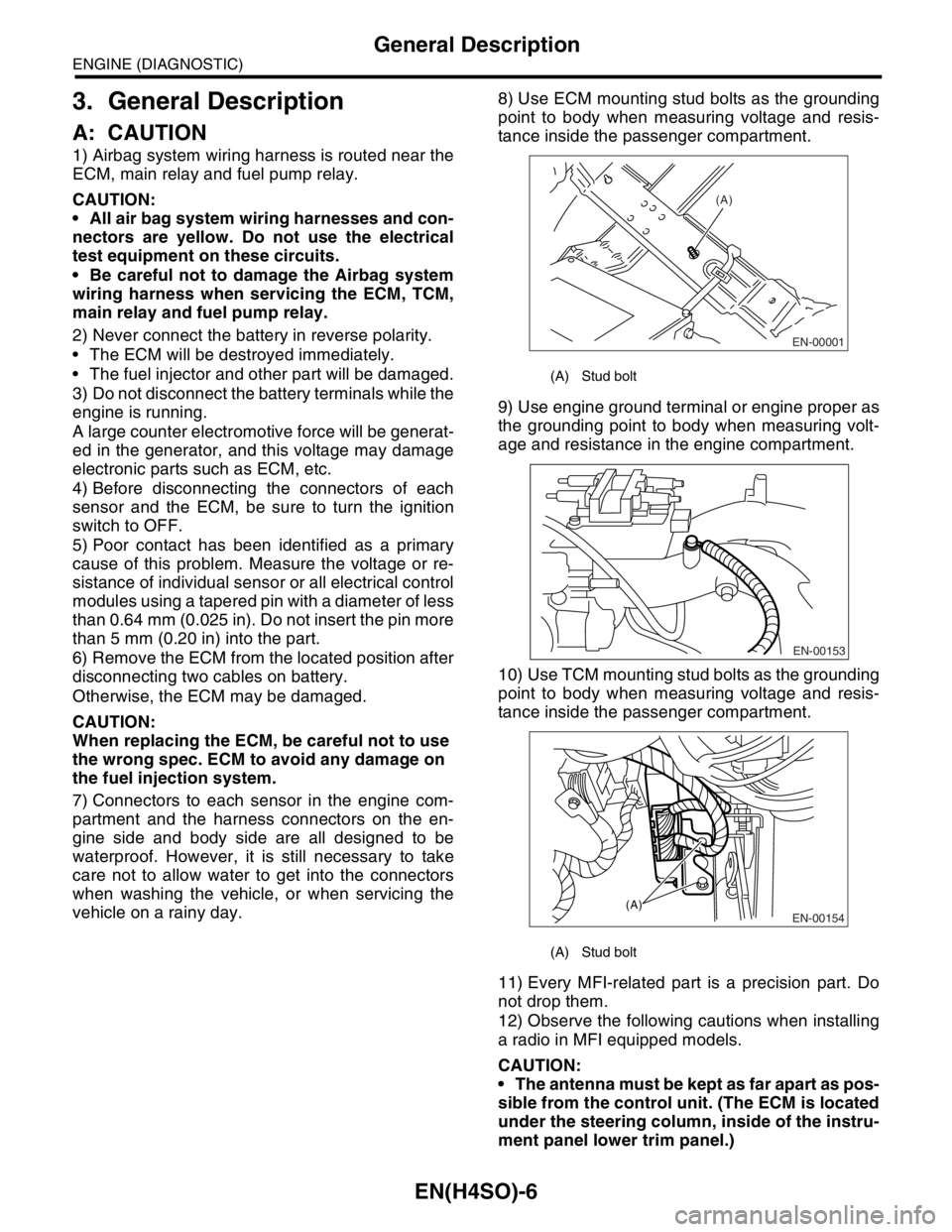
vehicle on a rainy day.8) Use ECM mounting stud bolts as the grounding
point to body when measuring voltage and resis-
tance inside the passenger compartment.
9) Use engine ground terminal or engine proper as
the grounding point to body when measuring volt-
age and resistance in the engine compartment.
10) Use TCM mounting stud bolts as the grounding
point to body when measuring voltage and resis-
tance inside the passenger compartment.
11) Every MFI-related part is a precision part. Do
not drop them.
12) Observe the following cautions when installing
a radio in MFI equipped models.
CAUTION:
The antenna must be kept as far apart as pos-
sible from the control unit. (The ECM is located
under the steering column, inside of the instru-
ment panel lower trim panel.)
(A) Stud bolt
(A) Stud bolt
EN-00001
(A)
EN-00153
EN-00154(A)
Page 1105 of 2870
EN(H4SO)-7
ENGINE (DIAGNOSTIC)
General Description
The antenna feeder must be placed as far
apart as possible from the ECM and MFI har-
ness.
Carefully adjust the antenna for correct
matching.
When mounting a large power type radio, pay
special attention to the three items above men-
tioned.
Incorrect installation of the radio may affect
the operation of the ECM.
13) Before disconnecting the fuel hose, disconnect
the fuel pump connector and crank the engine for
more than five seconds to release pressure in the
fuel system. If engine starts during this operation,
run it until it stops.
14) Problems in the electronic-controlled automatic
transmission may be caused by failure of the en-
gine, the electronic control system, the transmis-
sion proper, or by a combination of these. These
three causes must be distinguished clearly when
performing diagnostics.
15) Diagnostics should be conducted by rotating
with simple, easy operations and proceeding to
complicated, difficult operations. The most impor-
tant thing in diagnostics is to understand the cus-
tomer’s complaint, and distinguish between the
three causes.
16) In AT models, do not continue the stall for more
than five seconds. (from closed throttle, fully open
throttle to stall engine speed.)
17) On the model with ABS, when performing driv-
ing test in jacked-up or lifted-up position, some-
times the warning light may be lit, but this is not a
malfunction of the system. The reason for this is the
speed difference between the front and rear
wheels. After diagnosis of engine control system,
perform the ABS memory clearance procedure of
self-diagnosis function.
B: INSPECTION
Before performing diagnostics, check the following
items which might affect engine problems:
1. BATTERY
1) Measure battery voltage and specific gravity of
electrolyte.
Standard voltage: 12 V
Specific gravity: Above 1.260
2) Check the condition of the main and other fuses,
and harnesses and connectors. Also check for
proper grounding.
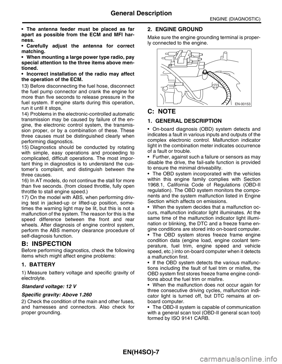
2. ENGINE GROUND
Make sure the engine grounding terminal is proper-
ly connected to the engine.
C: NOTE
1. GENERAL DESCRIPTION
On-board diagnosis (OBD) system detects and
indicates a fault in various inputs and outputs of the
complex electronic control. Malfunction indicator
light in the combination meter indicates occurrence
of a fault or trouble.
Further, against such a failure or sensors as may
disable the drive, the fail-safe function is provided
to ensure the minimal driveability.
The OBD system incorporated with the vehicles
within this engine family complies with Section
1968.1, California Code of Regulations (OBD-II
regulation). The OBD system monitors the compo-
nents and the system malfunction listed in Engine
Section which affects on emissions.
When the system decides that a malfunction oc-
curs, malfunction indicator light illuminates. At the
same time of the malfunction indicator light illumi-
nation or blinking, the DTC and a freeze frame en-
gine conditions are stored into on-board computer.
The OBD system stores freeze frame engine
condition data (engine load, engine coolant tem-
perature, fuel trim, engine speed and vehicle
speed, etc.) into on-board computer when it detects
a malfunction first.
If the OBD system detects the various malfunc-
tions including the fault of fuel trim or misfire, the
OBD system first stores freeze frame engine condi-
tions about the fuel trim or misfire.
When the malfunction does not occur again for
three consecutive driving cycles, malfunction indi-
cator light is turned off, but DTC remains at on-
board computer.
The OBD-II system is capable of communication
with a general scan tool (OBD-II general scan tool)
formed by ISO 9141 CARB.
EN-00153
Page 1128 of 2870
![SUBARU FORESTER 2004 Service Repair Manual EN(H4SO)-30
ENGINE (DIAGNOSTIC)
Subaru Select Monitor
4. READ CURRENT DATA FOR ENGINE. (NORMAL MODE)
1) On the «Main Menu» display screen, select the {Each System Check} and press the [YES] key.
2) SUBARU FORESTER 2004 Service Repair Manual EN(H4SO)-30
ENGINE (DIAGNOSTIC)
Subaru Select Monitor
4. READ CURRENT DATA FOR ENGINE. (NORMAL MODE)
1) On the «Main Menu» display screen, select the {Each System Check} and press the [YES] key.
2)](/manual-img/17/57426/w960_57426-1127.png)
EN(H4SO)-30
ENGINE (DIAGNOSTIC)
Subaru Select Monitor
4. READ CURRENT DATA FOR ENGINE. (NORMAL MODE)
1) On the «Main Menu» display screen, select the {Each System Check} and press the [YES] key.
2) On the «System Selection Menu» display screen, select the {Engine} and press the [YES] key.
3) Press the [YES] key after the information of engine type was displayed.
4) On the «Engine Diagnosis» display screen, select the {Current Data Display/Save}, and then press the
[YES] key.
5) On the «Data Display Menu» display screen, select the {Data Display} and press the [YES] key.
6) Using the scroll key, scroll the display screen up or down until the desired data is shown.
A list of the support data is shown in the following table.
Description Display Unit of measure
Battery voltage Battery Voltage V
Vehicle speed signal Meter vehicle speed km/h or MPH
Engine speed signal Engine speed rpm
Engine coolant temperature signal Engine coolant temperature°C or (°F)
Ignition timing signal Ignition timing deg
Throttle position signal Amount of intake air %
Throttle position signal Throttle Sensor Voltage V
Injection pulse width Fuel injection pulse width ms
Idle air control signal ISC Steps STEP
Engine load data Engine load %
Front oxygen (A/F) sensor resistance A/F sensor resistance value 1 ohm
Front oxygen (A/F) sensor output signal A/F sensor current value 1 —
Rear oxygen sensor output signalRear oxygen sensor voltage
valueV
Short term fuel trim A/F Compensation 1 %
Knock sensor signal Knock Correction deg
Atmospheric absolute pressure signal Atmospheric pressure mmHg, kPa, inHg or psi
Intake manifold relative pressure signal Mani. Relative Pressure mmHg, kPa, inHg or psi
Intake manifold absolute pressure signalIntake manifold absolute pres-
suremmHg, kPa, inHg or psi
A/F correction (short term fuel trim) by rear oxygen sensor A/F Compensation 3 %
Long term whole fuel trim A/F learning 1 %
Front oxygen (A/F) sensor heater current Front O2 heater current value A
Rear oxygen sensor heater current Rear O2 heater current value A
Canister purge control solenoid valve duty ratio CPC Valve Duty Ratio %
Fuel level signal Fuel level voltage V
Intake air temperature signal Intake air temperature°C or (°F)
Learned ignition timing Ignition learning value deg
EGR signal EGR Steps STEP
Ignition switch signal Ignition SW ON or OFF
Test mode connector signal Test mode signal ON or OFF
Neutral position switch signal Neutral SW ON or OFF
Air conditioning switch signal A/C SW ON or OFF
Air conditioning compressor signal A/C Compressor Signal ON or OFF
Radiator main fan relay signal Radiator fan relay 1 ON or OFF
Fuel pump relay signal Fuel pump relay ON or OFF
Knocking signal Knock signal ON or OFF
Radiator sub fan relay signal Radiator fan relay 2 ON or OFF
Power steering switch signal Power steering SW input signal ON or OFF
Engine torque control signal #1 AT coordinate request signal 1 ON or OFF
Engine torque control signal #2 AT coordinate request signal 2 ON or OFF