Page 469 of 2870
SR-5
SUNROOF/T-TOP/CONVERTIBLE TOP (SUNROOF)
Sunroof Lid
3. Sunroof Lid
A: REMOVAL
1) Completely close sunroof lid and open sunshade.
2) Detach the four covers (A) and then remove eight
nuts.
3) Carefully remove sunroof lid.
B: INSTALLATION
Install in the reverse order of removal.
C: ADJUSTMENT
1. ALIGNMENT OF HEIGHT BETWEEN
SUNROOF LID AND ROOF PANEL
Loosen sunroof lid nuts and then adjust height by add-
ing (max: four pieces) or extracting (min: zero piece)
shims (standard: two pieces) between sunroof lid and
roof panel.
Difference in height between sunroof lid and
roof panel
2.0
±1.0 mm (0.079±0.039 in)
SR-00002
(A) Shim
(B) Sunroof lid
(C) Roof panel
SR-00003
2.0 1.0 mm (0.079 0.039 in)
(B) (C)
(A)
Page 539 of 2870
EB-9
EXTERIOR BODY PANEL
Front Hood Panel
2. Front Hood Panel
A: REMOVAL
1) Open the front hood to remove washer nozzles.
2) Release the clips to remove front hood insulator.
3) Remove the bolts to remove front hood from hinges.
B: INSTALLATION
1) Install in the reverse order of removal.
2) Adjust the clearance between front hood panel
and front fender panel. Clearance must be equal at
both sides.
Tightening torque:
24.5 N·m (2.5 kgf-m, 18.1 ft-lb)
C: ADJUSTMENT
1) Use the hinge mounting holes to align the front
hood longitudinally and laterally.
2) Adjust the height at front end of hood.
SL-33, ADJUSTMENT, Front Hood Lock Assem-
bly.>3) Rotate the hood buffer to adjust lateral height.
EB-00008
EB-00009
EB-00009
EB-00010
Page 936 of 2870

ME(H4SO)-65
MECHANICAL
Cylinder Head
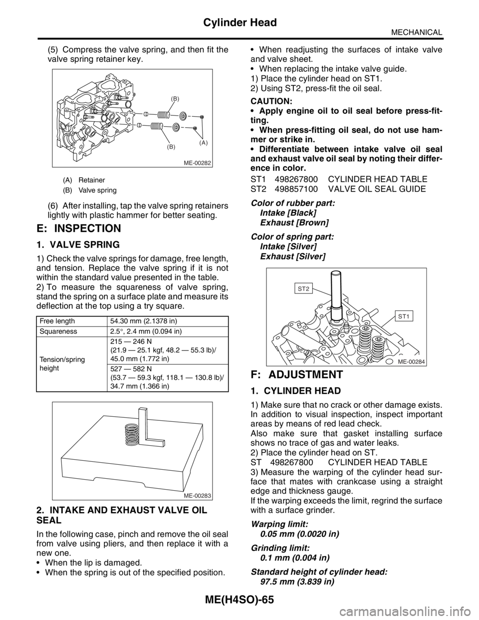
(5) Compress the valve spring, and then fit the
valve spring retainer key.
(6) After installing, tap the valve spring retainers
lightly with plastic hammer for better seating.
E: INSPECTION
1. VALVE SPRING
1) Check the valve springs for damage, free length,
and tension. Replace the valve spring if it is not
within the standard value presented in the table.
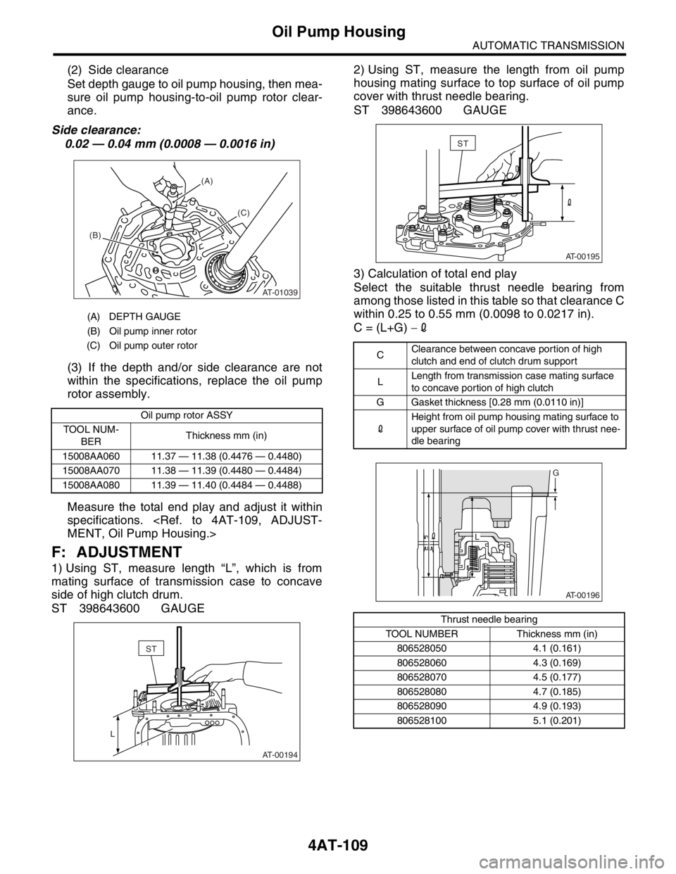
2) To measure the squareness of valve spring,
stand the spring on a surface plate and measure its
deflection at the top using a try square.
2. INTAKE AND EXHAUST VALVE OIL
SEAL
In the following case, pinch and remove the oil seal
from valve using pliers, and then replace it with a
new one.
When the lip is damaged.
When the spring is out of the specified position. When readjusting the surfaces of intake valve
and valve sheet.
When replacing the intake valve guide.
1) Place the cylinder head on ST1.
2) Using ST2, press-fit the oil seal.
CAUTION:
Apply engine oil to oil seal before press-fit-
ting.
When press-fitting oil seal, do not use ham-
mer or strike in.
Differentiate between intake valve oil seal
and exhaust valve oil seal by noting their differ-
ence in color.
ST1 498267800 CYLINDER HEAD TABLE
ST2 498857100 VALVE OIL SEAL GUIDE
Color of rubber part:
Intake [Black]
Exhaust [Brown]
Color of spring part:
Intake [Silver]
Exhaust [Silver]
F: ADJUSTMENT
1. CYLINDER HEAD
1) Make sure that no crack or other damage exists.
In addition to visual inspection, inspect important
areas by means of red lead check.
Also make sure that gasket installing surface
shows no trace of gas and water leaks.
2) Place the cylinder head on ST.
ST 498267800 CYLINDER HEAD TABLE
3) Measure the warping of the cylinder head sur-
face that mates with crankcase using a straight
edge and thickness gauge.
If the warping exceeds the limit, regrind the surface
with a surface grinder.
Warping limit:
0.05 mm (0.0020 in)
Grinding limit:
0.1 mm (0.004 in)
Standard height of cylinder head:
97.5 mm (3.839 in)
(A) Retainer
(B) Valve spring
Free length 54.30 mm (2.1378 in)
Squareness 2.5°, 2.4 mm (0.094 in)
Tension/spring
height215 — 246 N
(21.9 — 25.1 kgf, 48.2 — 55.3 lb)/
45.0 mm (1.772 in)
527 — 582 N
(53.7 — 59.3 kgf, 118.1 — 130.8 lb)/
34.7 mm (1.366 in)
ME-00282
(B)(B)
(A)
ME-00283
ME-00284
ST1
ST2
Page 2423 of 2870

4AT-109
AUTOMATIC TRANSMISSION
Oil Pump Housing
(2) Side clearance
Set depth gauge to oil pump housing, then mea-
sure oil pump housing-to-oil pump rotor clear-
ance.
Side clearance:
0.02 — 0.04 mm (0.0008 — 0.0016 in)
(3) If the depth and/or side clearance are not
within the specifications, replace the oil pump
rotor assembly.
Measure the total end play and adjust it within
specifications.
MENT, Oil Pump Housing.>
F: ADJUSTMENT
1) Using ST, measure length “L”, which is from
mating surface of transmission case to concave
side of high clutch drum.
ST 398643600 GAUGE2) Using ST, measure the length from oil pump
housing mating surface to top surface of oil pump
cover with thrust needle bearing.
ST 398643600 GAUGE
3) Calculation of total end play
Select the suitable thrust needle bearing from
among those listed in this table so that clearance C
within 0.25 to 0.55 mm (0.0098 to 0.0217 in).
C = (L+G) −2
(A) DEPTH GAUGE
(B) Oil pump inner rotor
(C) Oil pump outer rotor
Oil pump rotor ASSY
TOOL NUM-
BERThickness mm (in)
15008AA060 11.37 — 11.38 (0.4476 — 0.4480)
15008AA070 11.38 — 11.39 (0.4480 — 0.4484)
15008AA080 11.39 — 11.40 (0.4484 — 0.4488)
AT-01039
(A)
(B)
(C)
AT-00194
L
ST
CClearance between concave portion of high
clutch and end of clutch drum support
LLength from transmission case mating surface
to concave portion of high clutch
G Gasket thickness [0.28 mm (0.0110 in)]
2Height from oil pump housing mating surface to
upper surface of oil pump cover with thrust nee-
dle bearing
Thrust needle bearing
TOOL NUMBER Thickness mm (in)
806528050 4.1 (0.161)
806528060 4.3 (0.169)
806528070 4.5 (0.177)
806528080 4.7 (0.185)
806528090 4.9 (0.193)
806528100 5.1 (0.201)
AT-00195
ST
AT-00196
G
L