2004 SUBARU FORESTER clock
[x] Cancel search: clockPage 1087 of 2870
SC(H4SO)-12
STARTING/CHARGING SYSTEM
Starter
2. YOKE
Make sure the pole is set in position.
3. OVERRUNNING CLUTCH
Inspect the teeth of pinion for wear and damage.
Replace if it is damaged. Rotate the pinion in direc-
tion of rotation (counterclockwise). It should rotate
smoothly. But in opposite direction, it should be
locked.
CAUTION:
Do not clean the overrunning clutch with oil to
prevent grease from flowing out.
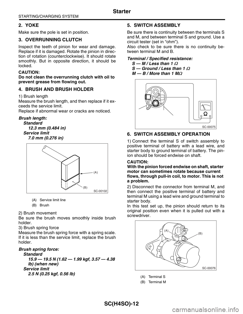
4. BRUSH AND BRUSH HOLDER
1) Brush length
Measure the brush length, and then replace if it ex-
ceeds the service limit.
Replace if abnormal wear or cracks are noticed.
Brush length:
Standard
12.3 mm (0.484 in)
Service limit
7.0 mm (0.276 in)
2) Brush movement
Be sure the brush moves smoothly inside brush
holder.
3) Brush spring force
Measure the brush spring force with a spring scale.
If it is less than the service limit, replace the brush
holder.
Brush spring force:
Standard
15.9 — 19.5 N (1.62 — 1.99 kgf, 3.57 — 4.38
lb) (when new)
Service limit
2.5 N (0.25 kgf, 0.56 lb)
5. SWITCH ASSEMBLY
Be sure there is continuity between the terminals S
and M, and between terminal S and ground. Use a
circuit tester (set in “ohm”).
Also check to be sure there is no continuity be-
tween terminal M and B.
Terminal / Specified resistance:
S — M / Less than 1
Ω
S — Ground / Less than 1 Ω
M — B / More than 1 MΩ
6. SWITCH ASSEMBLY OPERATION
1) Connect the terminal S of switch assembly to
positive terminal of battery with a lead wire, and
starter body to ground terminal of battery. The pin-
ion should be forced endwise on shaft.
CAUTION:
With the pinion forced endwise on shaft, starter
motor can sometimes rotate because current
flows, through pull-in coil, to motor. This is not
a problem.
2) Disconnect the connector from terminal M, and
then connect the positive terminal of battery and
terminal M using a lead wire and ground terminal to
starter body.
In this test set up, the pinion should return to its
original position even when it is pulled out with a
screwdriver.
(A) Service limit line
(B) Brush
SC-00102
(A)
(B)
(A) Terminal S
(B) Terminal M
SC-00075
B
M
S
SC-00076
(B) (A)
Page 1494 of 2870
ME(H4DOTC)-38
MECHANICAL
Valve Clearance
(5) Move the washer tank upward.
(6) Disconnect the ignition coil connector.
(7) Remove the ignition coil.
(8) Place a suitable container under the vehicle.
(9) Disconnect the PCV hose from rocker cover
(LH).
(10)Remove the bolts, and then remove the
rocker cover (LH).
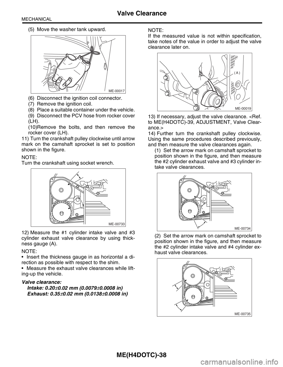
11) Turn the crankshaft pulley clockwise until arrow
mark on the camshaft sprocket is set to position
shown in the figure.
NOTE:
Turn the crankshaft using socket wrench.
12) Measure the #1 cylinder intake valve and #3
cylinder exhaust valve clearance by using thick-
ness gauge (A).
NOTE:
Insert the thickness gauge in as horizontal a di-
rection as possible with respect to the shim.
Measure the exhaust valve clearances while lift-
ing-up the vehicle.
Valve clearance:
Intake: 0.20
±0.02 mm (0.0079±0.0008 in)
Exhaust: 0.35
±0.02 mm (0.0138±0.0008 in)NOTE:
If the measured value is not within specification,
take notes of the value in order to adjust the valve
clearance later on.
13) If necessary, adjust the valve clearance.
ance.>
14) Further turn the crankshaft pulley clockwise.
Using the same procedures described previously,
and then measure the valve clearances again.
(1) Set the arrow mark on camshaft sprocket to
position shown in the figure, and then measure
the #2 cylinder exhaust valve and #3 cylinder in-
take valve clearances.
(2) Set the arrow mark on camshaft sprocket to
position shown in the figure, and then measure
the #2 cylinder intake valve and #4 cylinder ex-
haust valve clearances.
ME-00017
ME-00733
ME-00019
(A)
ME-00734
ME-00735
Page 1519 of 2870
ME(H4DOTC)-61
MECHANICAL
Timing Belt Assembly
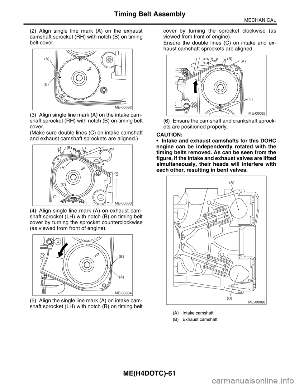
(2) Align single line mark (A) on the exhaust
camshaft sprocket (RH) with notch (B) on timing
belt cover.
(3) Align single line mark (A) on the intake cam-
shaft sprocket (RH) with notch (B) on timing belt
cover.
(Make sure double lines (C) on intake camshaft
and exhaust camshaft sprockets are aligned.)
(4) Align single line mark (A) on exhaust cam-
shaft sprocket (LH) with notch (B) on timing belt
cover by turning the sprocket counterclockwise
(as viewed from front of engine).
(5) Align the single line mark (A) on intake cam-
shaft sprocket (LH) with notch (B) on timing beltcover by turning the sprocket clockwise (as
viewed from front of engine).
Ensure the double lines (C) on intake and ex-
haust camshaft sprockets are aligned.
(6) Ensure the camshaft and crankshaft sprock-
ets are positioned properly.
CAUTION:
Intake and exhaust camshafts for this DOHC
engine can be independently rotated with the
timing belts removed. As can be seen from the
figure, if the intake and exhaust valves are lifted
simultaneously, their heads will interfere with
each other, resulting in bent valves.
ME-00082
(A)
(B)
ME-00083
(B)
(C)
(A)
ME-00084
(B)
(A)
(A) Intake camshaft
(B) Exhaust camshaft
ME-00085
(A) (B)
(C)
ME-00086
(A)
(B)
Page 1527 of 2870
ME(H4DOTC)-69
MECHANICAL
Camshaft
16) Remove the oil flow control solenoid valve as-
sembly, intake camshaft cap, and camshaft.
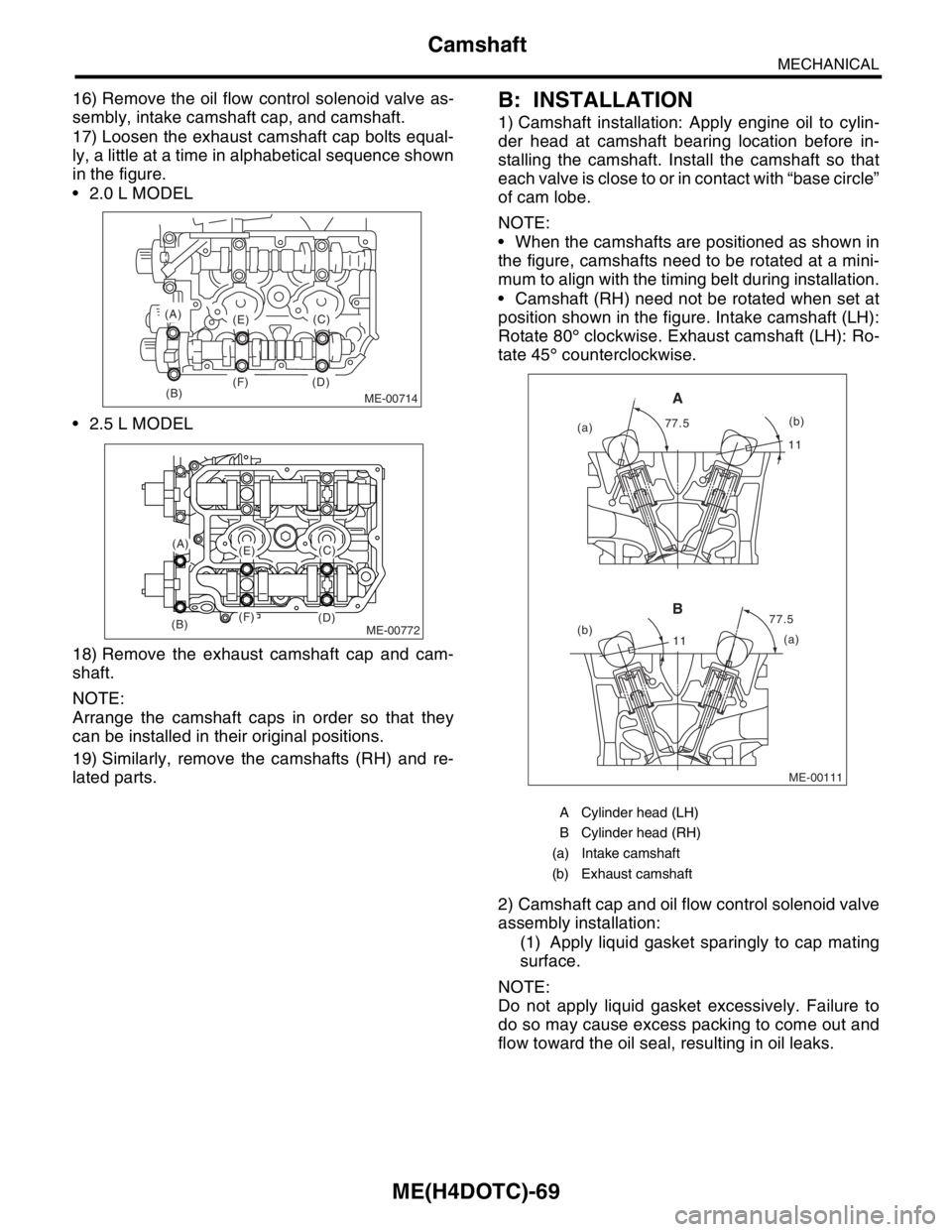
17) Loosen the exhaust camshaft cap bolts equal-
ly, a little at a time in alphabetical sequence shown
in the figure.
2.0 L MODEL
2.5 L MODEL
18) Remove the exhaust camshaft cap and cam-
shaft.
NOTE:
Arrange the camshaft caps in order so that they
can be installed in their original positions.
19) Similarly, remove the camshafts (RH) and re-
lated parts.B: INSTALLATION
1) Camshaft installation: Apply engine oil to cylin-
der head at camshaft bearing location before in-
stalling the camshaft. Install the camshaft so that
each valve is close to or in contact with “base circle”
of cam lobe.
NOTE:
When the camshafts are positioned as shown in
the figure, camshafts need to be rotated at a mini-
mum to align with the timing belt during installation.
Camshaft (RH) need not be rotated when set at
position shown in the figure. Intake camshaft (LH):
Rotate 80° clockwise. Exhaust camshaft (LH): Ro-
tate 45° counterclockwise.
2) Camshaft cap and oil flow control solenoid valve
assembly installation:
(1) Apply liquid gasket sparingly to cap mating
surface.
NOTE:
Do not apply liquid gasket excessively. Failure to
do so may cause excess packing to come out and
flow toward the oil seal, resulting in oil leaks.
ME-00714(B)
(A)
(E)
(F) (D)(C)
ME-00772
(A)(E)
(F)(B)(D)
(C)
A Cylinder head (LH)
B Cylinder head (RH)
(a) Intake camshaft
(b) Exhaust camshaft
ME-00111
1111
77.5 77.5
(a)
(b)
(a)(b)
A
B
Page 1537 of 2870
ME(H4DOTC)-79
MECHANICAL
Cylinder Head Assembly
3. VALVE GUIDE
1) Check the clearance between valve guide and
stem. The clearance can be checked by measuring
the outside diameter of valve stem and the inside
diameter of valve guide with outside and inside mi-
crometers respectively.
Clearance between the valve guide and valve
stem:
Standard
Intake
0.030 — 0.057 mm (0.0012 — 0.0022 in)
Exhaust
0.040 — 0.067 mm (0.0016 — 0.0026 in)
Limit
0.15 mm (0.0059 in)
2) If the clearance between valve guide and stem
exceeds the limit, replace the valve guide or valve
itself whichever shows greater amount of wear.
See the following procedure for valve guide re-
placement.
Valve guide inner diameter:
6.000 — 6.012 mm (0.2362 — 0.2367 in)
Valve stem outer diameters:
Intake
5.955 — 5.970 mm (0.2344 — 0.2350 in)
Exhaust
5.945 — 5.960 mm (0.2341 — 0.2346 in)
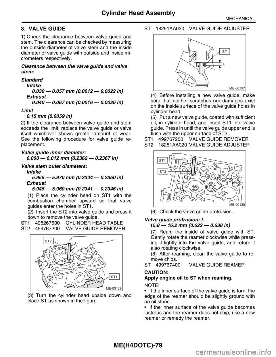
(1) Place the cylinder head on ST1 with the
combustion chamber upward so that valve
guides enter the holes in ST1.
(2) Insert the ST2 into valve guide and press it
down to remove the valve guide.
ST1 498267600 CYLINDER HEAD TABLE
ST2 499767200 VALVE GUIDE REMOVER
(3) Turn the cylinder head upside down and
place ST as shown in the figure.ST 18251AA020 VALVE GUIDE ADJUSTER
(4) Before installing a new valve guide, make
sure that neither scratches nor damages exist
on the inside surface of the valve guide holes in
cylinder head.
(5) Put a new valve guide, coated with sufficient
oil, in cylinder head, and insert ST1 into valve
guide. Press in until the valve guide upper end is
flush with the upper surface of ST2.
ST1 499767200 VALVE GUIDE REMOVER
ST2 18251AA020 VALVE GUIDE ADJUSTER
(6) Check the valve guide protrusion.
Valve guide protrusion: L
15.8 — 16.2 mm (0.622 — 0.638 in)
(7) Ream the inside of valve guide with ST.
Gently rotate the reamer clockwise while press-
ing it lightly into the valve guide, and return it
also rotating clockwise.
(8) After reaming, clean the valve guide to re-
move chips.
ST 499767400 VALVE GUIDE REAMER
CAUTION:
Apply engine oil to ST when reaming.
NOTE:
If the inner surface of the valve guide is torn, the
edge of the reamer should be slightly ground with
an oil stone.
If the inner surface of the valve guide becomes
lustrous and the reamer does not chip, use a new
reamer or remedy the reamer.
ME-00128
ST1
ST2ME-00757
ST
L
ME-00130
ST1
ST2
Page 2408 of 2870
4AT-95
AUTOMATIC TRANSMISSION
Transfer Clutch
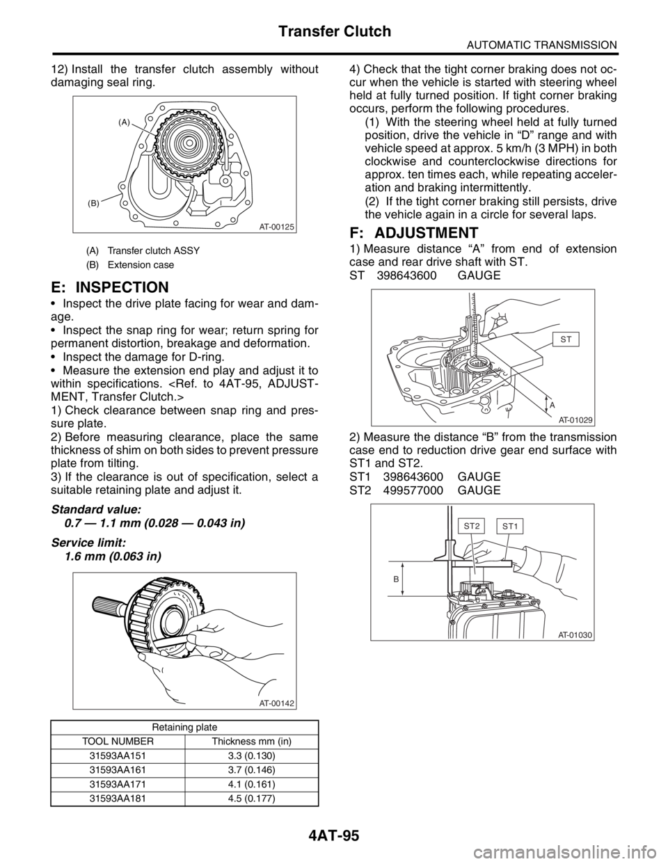
12) Install the transfer clutch assembly without
damaging seal ring.
E: INSPECTION
Inspect the drive plate facing for wear and dam-
age.
Inspect the snap ring for wear; return spring for
permanent distortion, breakage and deformation.
Inspect the damage for D-ring.
Measure the extension end play and adjust it to
within specifications.
1) Check clearance between snap ring and pres-
sure plate.
2) Before measuring clearance, place the same
thickness of shim on both sides to prevent pressure
plate from tilting.
3) If the clearance is out of specification, select a
suitable retaining plate and adjust it.
Standard value:
0.7 — 1.1 mm (0.028 — 0.043 in)
Service limit:
1.6 mm (0.063 in)4) Check that the tight corner braking does not oc-
cur when the vehicle is started with steering wheel
held at fully turned position. If tight corner braking
occurs, perform the following procedures.
(1) With the steering wheel held at fully turned
position, drive the vehicle in “D” range and with
vehicle speed at approx. 5 km/h (3 MPH) in both
clockwise and counterclockwise directions for
approx. ten times each, while repeating acceler-
ation and braking intermittently.
(2) If the tight corner braking still persists, drive
the vehicle again in a circle for several laps.
F: ADJUSTMENT
1) Measure distance “A” from end of extension
case and rear drive shaft with ST.
ST 398643600 GAUGE
2) Measure the distance “B” from the transmission
case end to reduction drive gear end surface with
ST1 and ST2.
ST1 398643600 GAUGE
ST2 499577000 GAUGE(A) Transfer clutch ASSY
(B) Extension case
Retaining plate
TOOL NUMBER Thickness mm (in)
31593AA151 3.3 (0.130)
31593AA161 3.7 (0.146)
31593AA171 4.1 (0.161)
31593AA181 4.5 (0.177)
AT-00125
(A)
(B)
AT-00142
AST
AT-01029
ST2ST1
B
AT-01030
Page 2454 of 2870
4AT-140
AUTOMATIC TRANSMISSION
AT Main Case
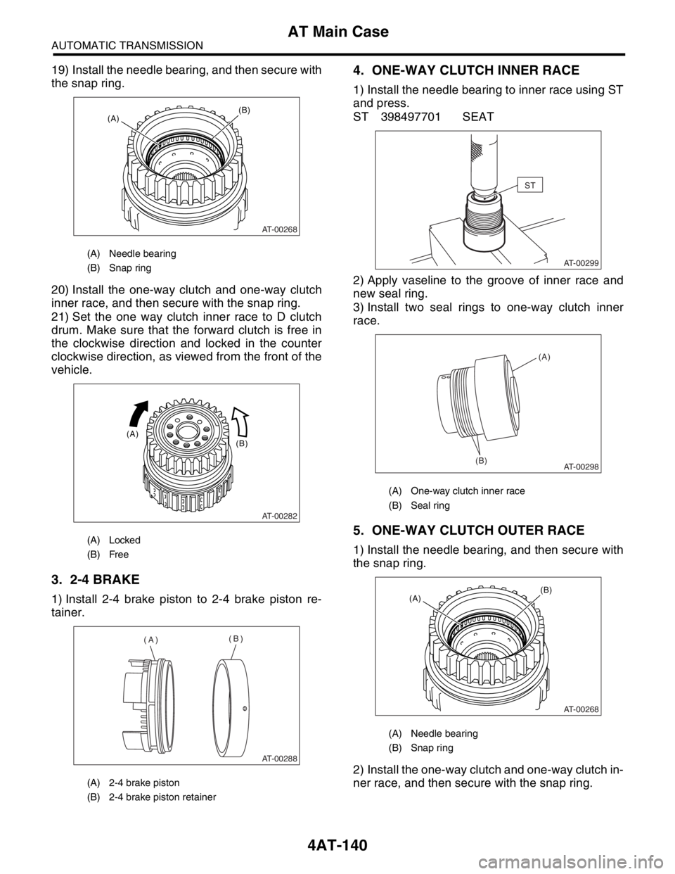
19) Install the needle bearing, and then secure with
the snap ring.
20) Install the one-way clutch and one-way clutch
inner race, and then secure with the snap ring.
21) Set the one way clutch inner race to D clutch
drum. Make sure that the forward clutch is free in
the clockwise direction and locked in the counter
clockwise direction, as viewed from the front of the
vehicle.
3. 2-4 BRAKE
1) Install 2-4 brake piston to 2-4 brake piston re-
tainer.
4. ONE-WAY CLUTCH INNER RACE
1) Install the needle bearing to inner race using ST
and press.
ST 398497701 SEAT
2) Apply vaseline to the groove of inner race and
new seal ring.
3) Install two seal rings to one-way clutch inner
race.
5. ONE-WAY CLUTCH OUTER RACE
1) Install the needle bearing, and then secure with
the snap ring.
2) Install the one-way clutch and one-way clutch in-
ner race, and then secure with the snap ring.
(A) Needle bearing
(B) Snap ring
(A) Locked
(B) Free
(A) 2-4 brake piston
(B) 2-4 brake piston retainer
AT-00268
(B)(A)
AT-00282
(B) (A)
AT-00288
(A)(B)
(A) One-way clutch inner race
(B) Seal ring
(A) Needle bearing
(B) Snap ring
ST
AT-00299
AT-00298(B)(A)
AT-00268
(B)(A)
Page 2455 of 2870
4AT-141
AUTOMATIC TRANSMISSION
AT Main Case
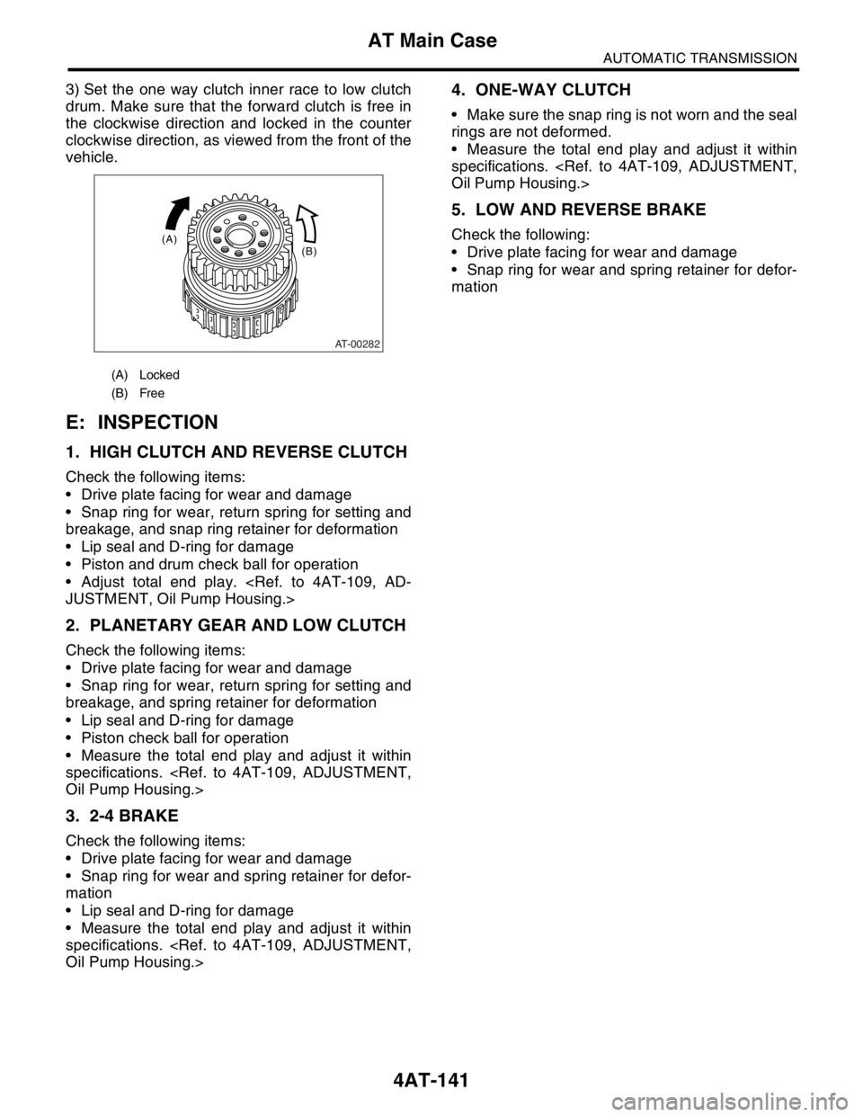
3) Set the one way clutch inner race to low clutch
drum. Make sure that the forward clutch is free in
the clockwise direction and locked in the counter
clockwise direction, as viewed from the front of the
vehicle.
E: INSPECTION
1. HIGH CLUTCH AND REVERSE CLUTCH
Check the following items:
Drive plate facing for wear and damage
Snap ring for wear, return spring for setting and
breakage, and snap ring retainer for deformation
Lip seal and D-ring for damage
Piston and drum check ball for operation
Adjust total end play.
2. PLANETARY GEAR AND LOW CLUTCH
Check the following items:
Drive plate facing for wear and damage
Snap ring for wear, return spring for setting and
breakage, and spring retainer for deformation
Lip seal and D-ring for damage
Piston check ball for operation
Measure the total end play and adjust it within
specifications.
3. 2-4 BRAKE
Check the following items:
Drive plate facing for wear and damage
Snap ring for wear and spring retainer for defor-
mation
Lip seal and D-ring for damage
Measure the total end play and adjust it within
specifications.
4. ONE-WAY CLUTCH
Make sure the snap ring is not worn and the seal
rings are not deformed.
Measure the total end play and adjust it within
specifications.
5. LOW AND REVERSE BRAKE
Check the following:
Drive plate facing for wear and damage
Snap ring for wear and spring retainer for defor-
mation
(A) Locked
(B) Free
AT-00282
(B) (A)