2004 SUBARU FORESTER stop start
[x] Cancel search: stop startPage 2653 of 2870

4AT(H4DOTC)-77
AUTOMATIC TRANSMISSION (DIAGNOSTIC)
Diagnostic Procedure with Diagnostic Trouble Code (DTC)
5 CHECK OUTPUT SIGNAL FROM TCM.
1) Connect all connectors.
2) Start the engine and warm-up the engine
until ATF temperature is above 80°C (176°F).
N
OTE:
If ambient temperature is below 0°C (32°F),
drive the vehicle until ATF reaches its operating
temperature.
3) Turn the ignition switch to ON (engine OFF).
4) Shift the select lever to “N” range.
5) Measure the voltage between TCM con-
nector and chassis ground.
Connector & terminal
(B56) No. 6 (+) — Chassis ground (
−):Is the voltage more than 10.5
V?Go to step 6.Go to step 9.
6 CHECK OUTPUT SIGNAL FROM TCM.
1) Shift the select lever to “2” range.
2) Turn the HOLD switch to ON.
3) Measure the voltage between TCM con-
nector and chassis ground.
Connector & terminal
(B56) No. 6 (+) — Chassis ground (
−):Is the voltage less than 1 V? Even if the POWER
indicator light was
blinking, the circuit
has returned to a
normal condition at
this time. A tempo-
rary poor contact of
the connector or
harness may be the
cause. Repair the
harness or connec-
tor in TCM and
transmission.Go to step 9.
7 CHECK OUTPUT SIGNAL FROM TCM US-
ING SUBARU SELECT MONITOR.
1) Connect all connectors.
2) Connect the Subaru Select Monitor to data
link connector.
3) Start the engine and turn Subaru Select
Monitor switch to ON.
4) Warm-up the transmission until ATF tem-
perature is above 80°C (176°F).
N
OTE:
If ambient temperature is below 0°C (32°F),
drive the vehicle until ATF reaches its operating
temperature.
5) Stop the engine and turn ignition switch to
ON (engine OFF).
6) Shift the select lever to “N” range.
7) Read the data of 2-4 brake duty solenoid
using Subaru Select Monitor.
2-4 brake duty solenoid is indicated in “%”.Is the value 100%? Go to step 8.Go to step 9.
8 CHECK OUTPUT SIGNAL FROM TCM US-
ING SUBARU SELECT MONITOR.
1) Shift the select lever to “2” range.
2) Turn the HOLD switch to ON.Is the value 0%? Even if the POWER
indicator light was
blinking, the circuit
has returned to a
normal condition at
this time. A tempo-
rary poor contact of
the connector or
harness may be the
cause. Repair the
harness or connec-
tor in TCM and
transmission.Go to step 9. Step Check Yes No
Page 2660 of 2870

4AT(H4DOTC)-84
AUTOMATIC TRANSMISSION (DIAGNOSTIC)
Diagnostic Procedure with Diagnostic Trouble Code (DTC)
5 CHECK OUTPUT SIGNAL FROM TCM.
1) Connect all connectors.
2) Start the engine and warm-up the engine
until ATF temperature is above 80°C (176°F).
N
OTE:
If ambient temperature is below 0°C (32°F),
drive the vehicle until ATF reaches its operating
temperature.
3) Turn the ignition switch to ON (engine
OFF).
4) Shift the select lever to “N” range.
5) Measure the voltage between TCM con-
nector and chassis ground.
Connector & terminal
(B56) No. 7 (+) — Chassis ground (
−):Is the voltage more than 10.5
V?Go to step 6.Go to step 9.
6 CHECK OUTPUT SIGNAL FROM TCM.
1) Shift the select lever to “1” range.
2) Measure the voltage between TCM con-
nector and chassis ground.
Connector & terminal
(B56) No. 7 (+) — Chassis ground (
−):Is the voltage less than 5 — 9
V? Even if the POWER
indicator light was
blinking, the circuit
has returned to a
normal condition at
this time. A tempo-
rary poor contact of
the connector or
harness may be the
cause. Repair the
harness or connec-
tor in TCM and
transmission.Go to step 9.
7 CHECK OUTPUT SIGNAL FROM TCM US-
ING SUBARU SELECT MONITOR.
1) Connect all connectors.
2) Connect the Subaru Select Monitor to data
link connector.
3) Start the engine and turn Subaru Select
Monitor switch to ON.
4) Warm-up the transmission until ATF tem-
perature is above 80°C (176°F).
N
OTE:
If ambient temperature is below 0°C (32°F),
drive the vehicle until ATF reaches its operating
temperature.
5) Stop the engine and turn ignition switch to
ON (engine OFF).
6) Move the select lever to “N” range.
7) Read the data of low & reverse duty sole-
noid using Subaru Select Monitor.
Low & reverse brake duty solenoid is indi-
cated in “%”.Is the value 100%? Go to step 8.Go to step 9. Step Check Yes No
Page 2748 of 2870

5MT-36
MANUAL TRANSMISSION AND DIFFERENTIAL
Manual Transmission Assembly
B: INSTALLATION
1) Replace the differential side retainer oil seal with
a new one.
NOTE:
When pulling out the front drive shaft, always re-
place the differential side retainer oil seal.
2) Install the rear cushion rubber to transmission
assembly.
Tightening torque:
35 N·m (3.57 kgf-m, 25.8 ft-lb)
3) Install the clutch release lever and bearing onto
transmission. (Turbo model)
4) Install the transmission onto engine.
(1) Gradually raise the transmission with trans-
mission jack.
(2) Engage them at splines.
NOTE:
Be careful not to strike the main shaft against clutch
cover.
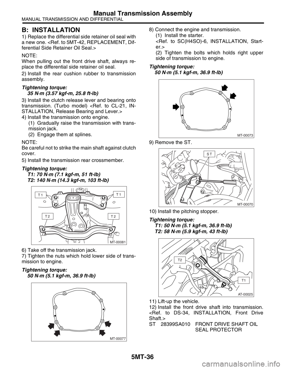
5) Install the transmission rear crossmember.
Tightening torque:
T1: 70 N·m (7.1 kgf-m, 51 ft-lb)
T2: 140 N·m (14.3 kgf-m, 103 ft-lb)
6) Take off the transmission jack.
7) Tighten the nuts which hold lower side of trans-
mission to engine.
Tightening torque:
50 N·m (5.1 kgf-m, 36.9 ft-lb)8) Connect the engine and transmission.
(1) Install the starter.
(2) Tighten the bolts which holds right upper
side of transmission to engine.
Tightening torque:
50 N·m (5.1 kgf-m, 36.9 ft-lb)
9) Remove the ST.
10) Install the pitching stopper.
Tightening torque:
T1: 50 N·m (5.1 kgf-m, 36.9 ft-lb)
T2: 58 N·m (5.9 kgf-m, 43 ft-lb)
11) Lift-up the vehicle.
12) Install the front drive shaft into transmission.
ST 28399SA010 FRONT DRIVE SHAFT OIL
SEAL PROTECTOR
MT-00081
T2T2
T1T1
MT-00077
MT-00073
MT-00070
ST
AT-00025
T1
T2
Page 2807 of 2870

5MT-94
MANUAL TRANSMISSION AND DIFFERENTIAL
Drive Pinion Shaft Assembly
F: ADJUSTMENT
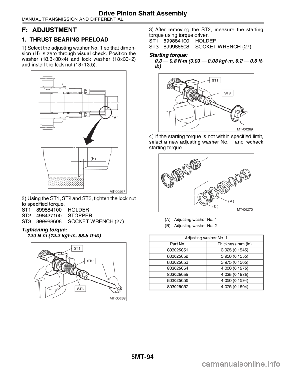
1. THRUST BEARING PRELOAD
1) Select the adjusting washer No. 1 so that dimen-
sion (H) is zero through visual check. Position the
washer (18.3×30×4) and lock washer (18×30×2)
and install the lock nut (18×13.5).
2) Using the ST1, ST2 and ST3, tighten the lock nut
to specified torque.
ST1 899884100 HOLDER
ST2 498427100 STOPPER
ST3 899988608 SOCKET WRENCH (27)
Tightening torque:
120 N·m (12.2 kgf-m, 88.5 ft-lb) 3) After removing the ST2, measure the starting
torque using torque driver.
ST1 899884100 HOLDER
ST3 899988608 SOCKET WRENCH (27)
Starting torque:
0.3 — 0.8 N·m (0.03 — 0.08 kgf-m, 0.2 — 0.6 ft-
lb)
4) If the starting torque is not within specified limit,
select a new adjusting washer No. 1 and recheck
starting torque.
MT-00267 (H)
MT-00268
ST1
ST2
ST3
(A) Adjusting washer No. 1
(B) Adjusting washer No. 2
Adjusting washer No. 1
Part No. Thickness mm (in)
803025051 3.925 (0.1545)
803025052 3.950 (0.1555)
803025053 3.975 (0.1565)
803025054 4.000 (0.1575)
803025055 4.025 (0.1585)
803025056 4.050 (0.1594)
803025057 4.075 (0.1604)
MT-00269
ST1
ST3
MT-00270
(A)
(B)
Page 2868 of 2870

CL-42
CLUTCH SYSTEM
General Diagnostic Table
12.General Diagnostic Table
A: INSPECTION
1. CLUTCH
Symptom Possible cause Corrective
1. Clutch slippage.
It is hard to perceive clutch slippage in
the early stage, but pay attention to the
following symptoms
Engine speed up when shifting.
High speed driving is impossible; espe-
cially rapid acceleration impossible and
vehicle speed does not increase in pro-
portion to an increase in engine speed.
Power falls, particularly when ascend-
ing a slope, and there is a smell of burn-
ing of the clutch facing.
Method of testing: Put the vehicle in
stationary condition with parking brake
fully applied. Disengage the clutch and
shift the transmission gear into the first.
Gradually allow the clutch to engage
while gradually increasing the engine
speed. The clutch function is satisfactory
if the engine stalls. However, the clutch is
slipping if the vehicle does not start off
and the engine does not stall.(a) Clutch facing smeared by oil Replace.
(b) Worn clutch facing Replace.
(c) Deteriorated diaphragm spring Replace.
(d) Distorted pressure plate or flywheel Replace.
(e) Defective release bearing holder Replace.
2. Clutch drags.
As a symptom of this trouble, a harsh
scratching noise develops and control
becomes quite difficult when shifting
gears. The symptom becomes more
apparent when shifting into the first gear.
However, because much trouble of this
sort is due to defective synchronization
mechanism, carry out the test as
described after.
Method of testing:
DRAG, INSPECTION, General Diagnos-
tic Table.>
It may be judged as insufficient disen-
gagement of clutch if any noise occurs
during this test.(a) Worn or rusty clutch disc hub spline Replace the clutch disc.
(b) Excessive deflection of clutch disc
facingReplace.
(c) Malfunction of crankshaft pilot bearing Replace.
(d) Cracked clutch disc facing Replace.
(e) Stuck clutch disc (smeared by oil or
water)Replace.
3. Clutch chatters.
Clutch chattering is an unpleasant vibra-
tion to the whole body when the vehicle is
just started with clutch partially engaged.(a) Adhesion of oil on the facing Replace the clutch disc.
(b) Weak or broken torsion spring Replace the clutch disc.
(c) Defective facing contact or excessive
disc wornReplace the clutch disc defection.
(d) Warped pressure plate or flywheel Replace.
(e) Loose disc rivets Replace the clutch disc.
(f) Loose engine mounting Retighten or replace the mounting.
(g) Improper adjustment of pitching stop-
perAdjustment.