2004 SUBARU FORESTER stop start
[x] Cancel search: stop startPage 757 of 2870
PM-20
PERIODIC MAINTENANCE SERVICE
Cooling System
11.Cooling System
A: INSPECTION
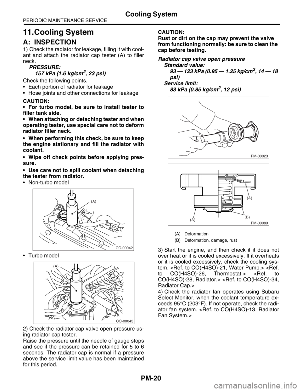
1) Check the radiator for leakage, filling it with cool-
ant and attach the radiator cap tester (A) to filler
neck.
PRESSURE:
157 kPa (1.6 kg/cm
2, 23 psi)
Check the following points.
Each portion of radiator for leakage
Hose joints and other connections for leakage
CAUTION:
For turbo model, be sure to install tester to
filler tank side.
When attaching or detaching tester and when
operating tester, use special care not to deform
radiator filler neck.
When performing this check, be sure to keep
the engine stationary and fill the radiator with
coolant.
Wipe off check points before applying pres-
sure.
Use care not to spill coolant when detaching
the tester from radiator.
Non-turbo model
Turbo model
2) Check the radiator cap valve open pressure us-
ing radiator cap tester.
Raise the pressure until the needle of gauge stops
and see if the pressure can be retained for 5 to 6
seconds. The radiator cap is normal if a pressure
above the service limit value has been maintained
for this period.CAUTION:
Rust or dirt on the cap may prevent the valve
from functioning normally: be sure to clean the
cap before testing.
Radiator cap valve open pressure
Standard value:
93 — 123 kPa (0.95 — 1.25 kg/cm2, 14 — 18
psi)
Service limit:
83 kPa (0.85 kg/cm
2, 12 psi)
3) Start the engine, and then check if it does not
over heat or it is cooled excessively. If it overheats
or it is cooled excessively, check the cooling sys-
tem.
4) Check the radiator fan operates using Subaru
Select Monitor, when the coolant temperature ex-
ceeds 95°C (203°F). If not operate, check the radi-
ator fan system.
CO-00042
(A)
CO-00043
(A)
(A) Deformation
(B) Deformation, damage, rust
PM-00023
PM-00089
(B)
(A)(A)
Page 762 of 2870

PM-25
PERIODIC MAINTENANCE SERVICE
Hill-holder System
15.Hill-holder System
A: INSPECTION AND ADJUSTMENT
1) Confirm the stopping and starting performance
by activating the hill-holder on an uphill road of 3°
or higher inclination.
(1) When the vehicle does not stop;
Tighten the adjusting nut of PHV cable.
(2) When the vehicle does not start properly;
A; When the hill-holder is released later than en-
gagement of clutch (engine tends to stall): Loos-
en the adjusting nut gradually until smooth
starting is enabled.
B; When the hill-holder is released earlier than
engagement to clutch (vehicle slips down slight-
ly): Tighten the adjusting nut so that hill-holder is
released later than engagement of clutch (status
in A). Then make adjustment the same as in A.
CAUTION:
Whenever turning the adjusting nut, hold the
inner cable with pliers to prevent it from turn-
ing.
Replace the pressure hold valve (PHV) or
PHV cable with a new one, if they are defective
and/or damaged.
(A) Lock nut
(B) Adjusting nut
(C) Pressure hold valve
(C) (B)
(A)
PM-00077
Page 768 of 2870
PM-31
PERIODIC MAINTENANCE SERVICE
Brake Line
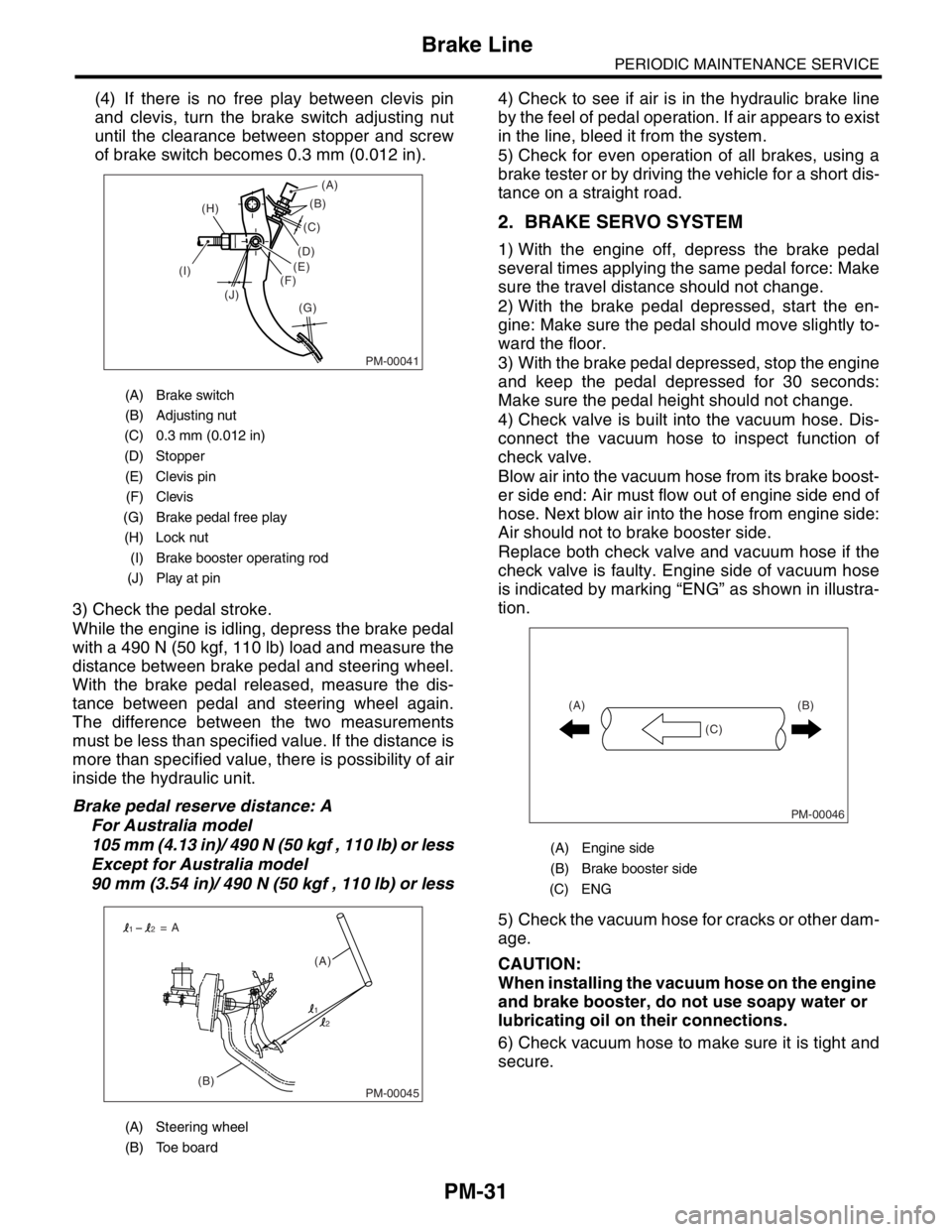
(4) If there is no free play between clevis pin
and clevis, turn the brake switch adjusting nut
until the clearance between stopper and screw
of brake switch becomes 0.3 mm (0.012 in).
3) Check the pedal stroke.
While the engine is idling, depress the brake pedal
with a 490 N (50 kgf, 110 lb) load and measure the
distance between brake pedal and steering wheel.
With the brake pedal released, measure the dis-
tance between pedal and steering wheel again.
The difference between the two measurements
must be less than specified value. If the distance is
more than specified value, there is possibility of air
inside the hydraulic unit.
Brake pedal reserve distance: A
For Australia model
105 mm (4.13 in)/ 490 N (50 kgf , 110 lb) or less
Except for Australia model
90 mm (3.54 in)/ 490 N (50 kgf , 110 lb) or less4) Check to see if air is in the hydraulic brake line
by the feel of pedal operation. If air appears to exist
in the line, bleed it from the system.
5) Check for even operation of all brakes, using a
brake tester or by driving the vehicle for a short dis-
tance on a straight road.
2. BRAKE SERVO SYSTEM
1) With the engine off, depress the brake pedal
several times applying the same pedal force: Make
sure the travel distance should not change.
2) With the brake pedal depressed, start the en-
gine: Make sure the pedal should move slightly to-
ward the floor.
3) With the brake pedal depressed, stop the engine
and keep the pedal depressed for 30 seconds:
Make sure the pedal height should not change.
4) Check valve is built into the vacuum hose. Dis-
connect the vacuum hose to inspect function of
check valve.
Blow air into the vacuum hose from its brake boost-
er side end: Air must flow out of engine side end of
hose. Next blow air into the hose from engine side:
Air should not to brake booster side.
Replace both check valve and vacuum hose if the
check valve is faulty. Engine side of vacuum hose
is indicated by marking “ENG” as shown in illustra-
tion.
5) Check the vacuum hose for cracks or other dam-
age.
CAUTION:
When installing the vacuum hose on the engine
and brake booster, do not use soapy water or
lubricating oil on their connections.
6) Check vacuum hose to make sure it is tight and
secure.
(A) Brake switch
(B) Adjusting nut
(C) 0.3 mm (0.012 in)
(D) Stopper
(E) Clevis pin
(F) Clevis
(G) Brake pedal free play
(H) Lock nut
(I) Brake booster operating rod
(J) Play at pin
(A) Steering wheel
(B) Toe board
PM-00041
(B)
(G) (H)
(I)
(J)(C)
(D)
(E)
(F)(A)
PM-00045(B)(A) = A
1
12
2
(A) Engine side
(B) Brake booster side
(C) ENG
PM-00046
(B)
(C) (A)
Page 895 of 2870
ME(H4SO)-26
MECHANICAL
Idle Speed
3. Idle Speed
A: INSPECTION
1) Before checking idle speed, check the following:
(1) Ensure the air cleaner element is free from
clogging, ignition timing is correct, spark plugs
are in good condition, and the hoses are con-
nected properly.
(2) Ensure the malfunction indicator light does
not illuminate.
2) Warm-up the engine.
3) Stop the engine, and then turn the ignition switch
to OFF.
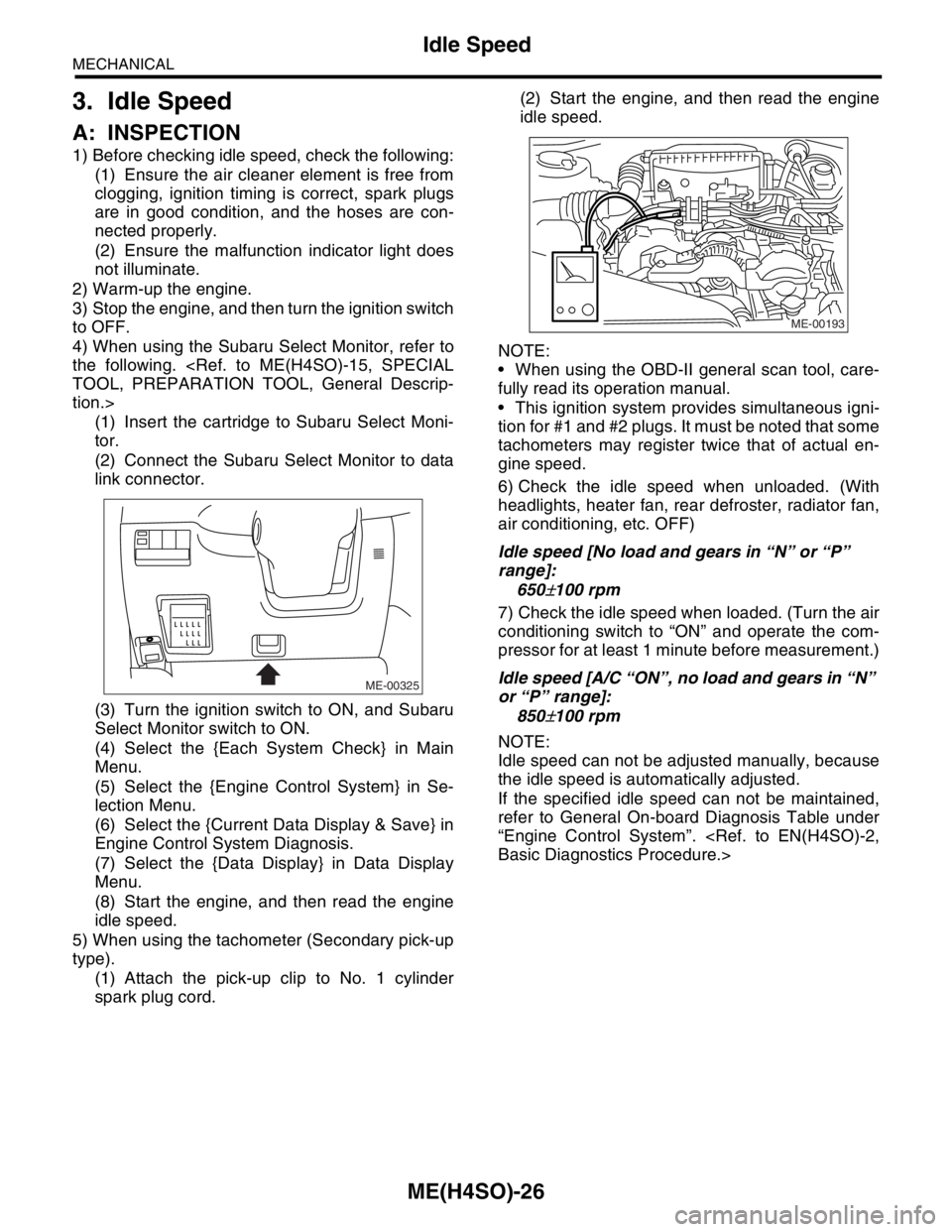
4) When using the Subaru Select Monitor, refer to
the following.
tion.>
(1) Insert the cartridge to Subaru Select Moni-
tor.
(2) Connect the Subaru Select Monitor to data
link connector.
(3) Turn the ignition switch to ON, and Subaru
Select Monitor switch to ON.
(4) Select the {Each System Check} in Main
Menu.
(5) Select the {Engine Control System} in Se-
lection Menu.
(6) Select the {Current Data Display & Save} in
Engine Control System Diagnosis.
(7) Select the {Data Display} in Data Display
Menu.
(8) Start the engine, and then read the engine
idle speed.
5) When using the tachometer (Secondary pick-up
type).
(1) Attach the pick-up clip to No. 1 cylinder
spark plug cord.(2) Start the engine, and then read the engine
idle speed.
NOTE:
When using the OBD-II general scan tool, care-
fully read its operation manual.
This ignition system provides simultaneous igni-
tion for #1 and #2 plugs. It must be noted that some
tachometers may register twice that of actual en-
gine speed.
6) Check the idle speed when unloaded. (With
headlights, heater fan, rear defroster, radiator fan,
air conditioning, etc. OFF)
Idle speed [No load and gears in “N” or “P”
range]:
650
±100 rpm
7) Check the idle speed when loaded. (Turn the air
conditioning switch to “ON” and operate the com-
pressor for at least 1 minute before measurement.)
Idle speed [A/C “ON”, no load and gears in “N”
or “P” range]:
850
±100 rpm
NOTE:
Idle speed can not be adjusted manually, because
the idle speed is automatically adjusted.
If the specified idle speed can not be maintained,
refer to General On-board Diagnosis Table under
“Engine Control System”.
ME-00325
ME-00193
Page 906 of 2870
ME(H4SO)-37
MECHANICAL
Engine Assembly
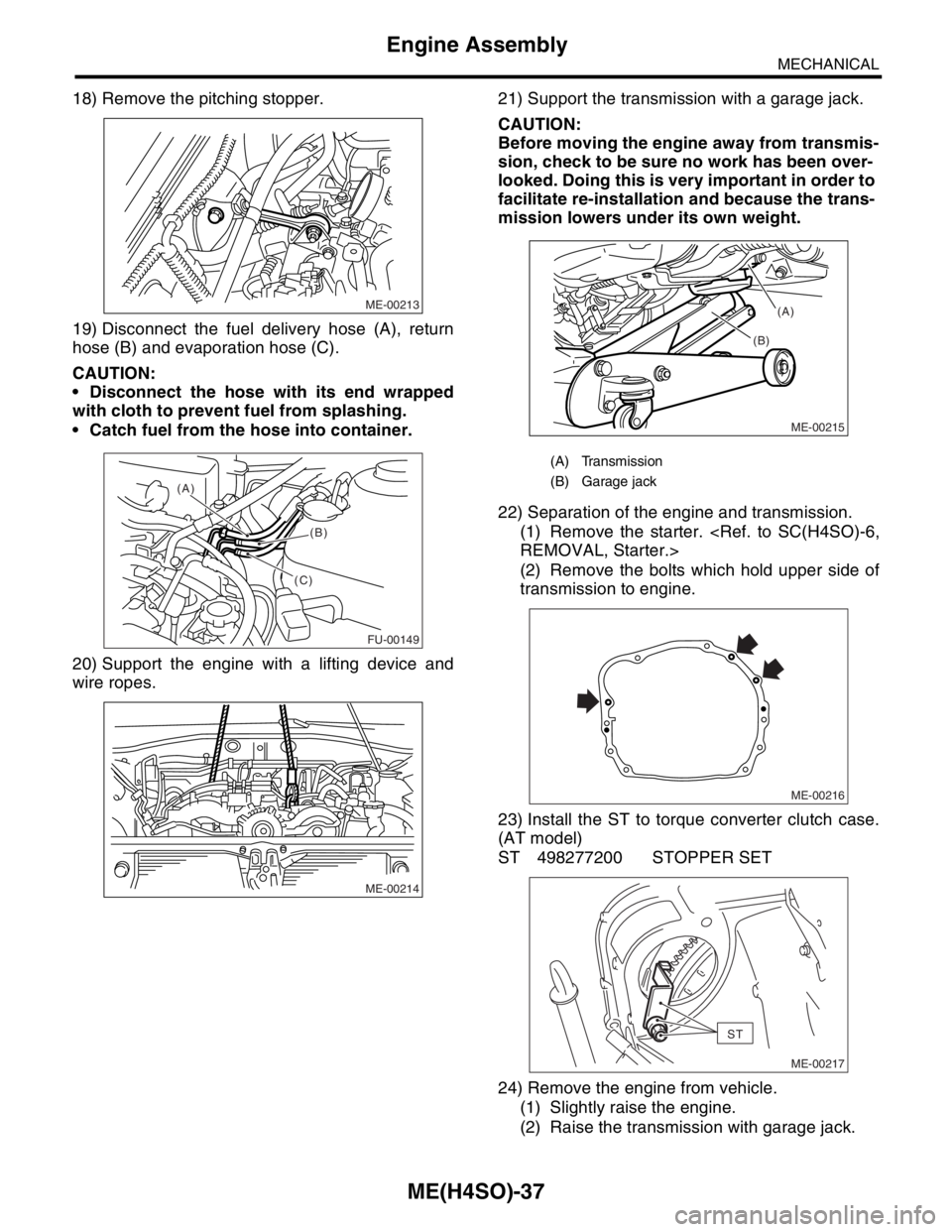
18) Remove the pitching stopper.
19) Disconnect the fuel delivery hose (A), return
hose (B) and evaporation hose (C).
CAUTION:
Disconnect the hose with its end wrapped
with cloth to prevent fuel from splashing.
Catch fuel from the hose into container.
20) Support the engine with a lifting device and
wire ropes.21) Support the transmission with a garage jack.
CAUTION:
Before moving the engine away from transmis-
sion, check to be sure no work has been over-
looked. Doing this is very important in order to
facilitate re-installation and because the trans-
mission lowers under its own weight.
22) Separation of the engine and transmission.
(1) Remove the starter.
(2) Remove the bolts which hold upper side of
transmission to engine.
23) Install the ST to torque converter clutch case.
(AT model)
ST 498277200 STOPPER SET
24) Remove the engine from vehicle.
(1) Slightly raise the engine.
(2) Raise the transmission with garage jack.
ME-00213
FU-00149
(A)
(B)
(C)
ME-00214
(A) Transmission
(B) Garage jack
ME-00215
(B)(A)
ME-00216
ST
ME-00217
Page 907 of 2870
ME(H4SO)-38
MECHANICAL
Engine Assembly
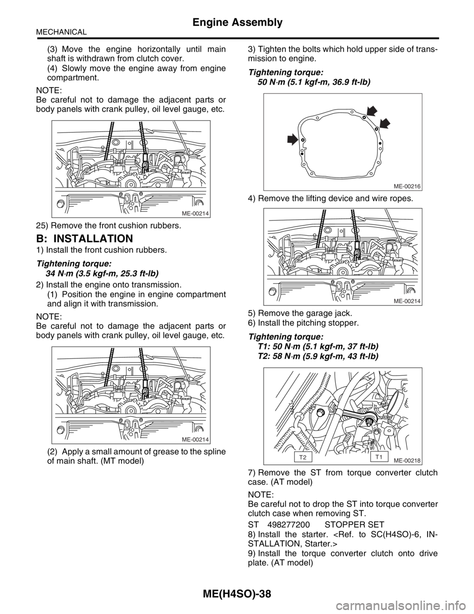
(3) Move the engine horizontally until main
shaft is withdrawn from clutch cover.
(4) Slowly move the engine away from engine
compartment.
NOTE:
Be careful not to damage the adjacent parts or
body panels with crank pulley, oil level gauge, etc.
25) Remove the front cushion rubbers.
B: INSTALLATION
1) Install the front cushion rubbers.
Tightening torque:
34 N
⋅m (3.5 kgf-m, 25.3 ft-lb)
2) Install the engine onto transmission.
(1) Position the engine in engine compartment
and align it with transmission.
NOTE:
Be careful not to damage the adjacent parts or
body panels with crank pulley, oil level gauge, etc.
(2) Apply a small amount of grease to the spline
of main shaft. (MT model)3) Tighten the bolts which hold upper side of trans-
mission to engine.
Tightening torque:
50 N
⋅m (5.1 kgf-m, 36.9 ft-lb)
4) Remove the lifting device and wire ropes.
5) Remove the garage jack.
6) Install the pitching stopper.
Tightening torque:
T1: 50 N
⋅m (5.1 kgf-m, 37 ft-lb)
T2: 58 N
⋅m (5.9 kgf-m, 43 ft-lb)
7) Remove the ST from torque converter clutch
case. (AT model)
NOTE:
Be careful not to drop the ST into torque converter
clutch case when removing ST.
ST 498277200 STOPPER SET
8) Install the starter.
9) Install the torque converter clutch onto drive
plate. (AT model)
ME-00214
ME-00214
ME-00216
ME-00214
ME-00218T2T1
Page 1039 of 2870
LU(H4SO)-11
LUBRICATION
Engine Oil
6) Tighten the engine oil drain plug after draining
engine oil.
Tightening torque:
44 N
⋅m (4.5 kgf-m, 32.5 ft-lb)
7) Install the service hole cover.
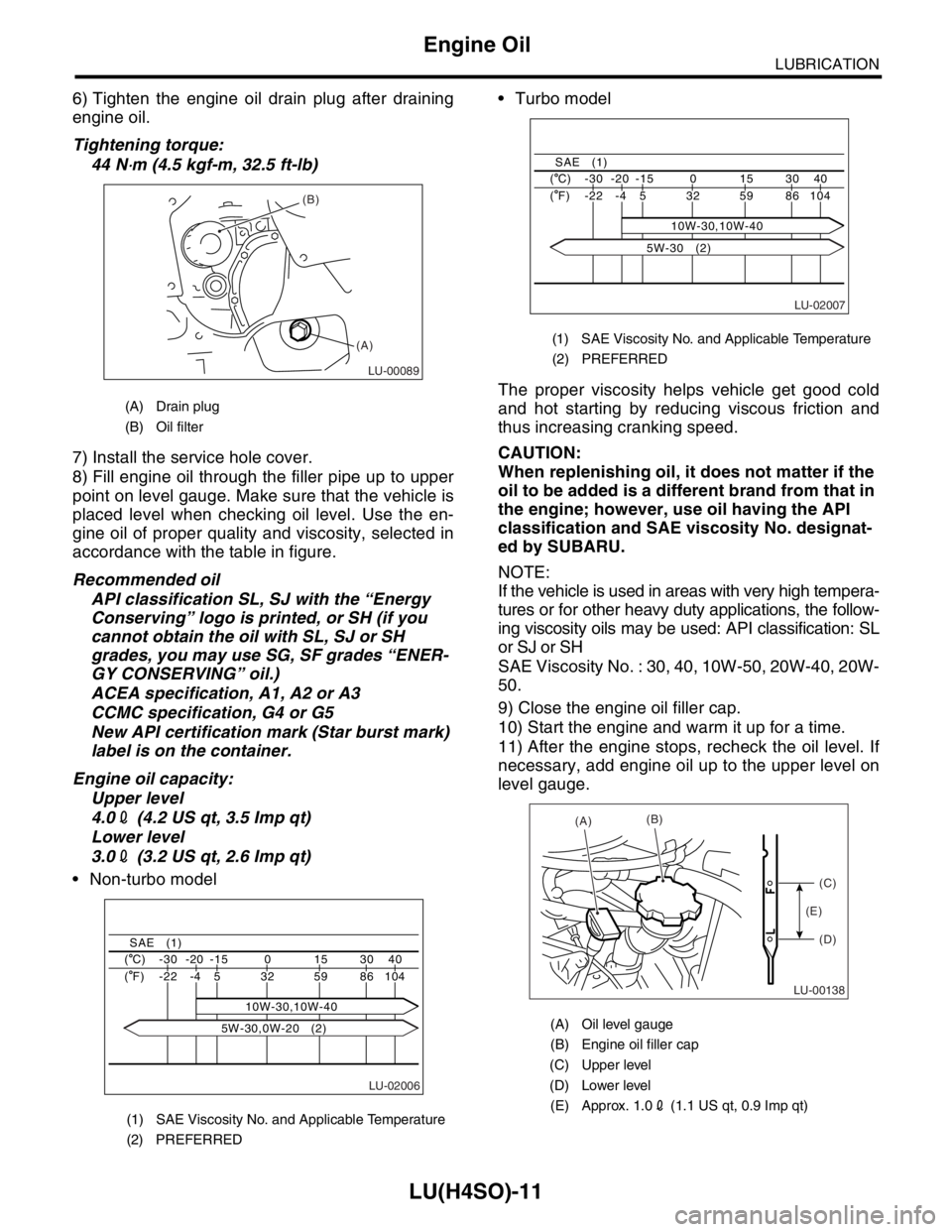
8) Fill engine oil through the filler pipe up to upper
point on level gauge. Make sure that the vehicle is
placed level when checking oil level. Use the en-
gine oil of proper quality and viscosity, selected in
accordance with the table in figure.
Recommended oil
API classification SL, SJ with the “Energy
Conserving” logo is printed, or SH (if you
cannot obtain the oil with SL, SJ or SH
grades, you may use SG, SF grades “ENER-
GY CONSERVING” oil.)
ACEA specification, A1, A2 or A3
CCMC specification, G4 or G5
New API certification mark (Star burst mark)
label is on the container.
Engine oil capacity:
Upper level
4.02 (4.2 US qt, 3.5 Imp qt)
Lower level
3.02 (3.2 US qt, 2.6 Imp qt)
Non-turbo model Turbo model
The proper viscosity helps vehicle get good cold
and hot starting by reducing viscous friction and
thus increasing cranking speed.
CAUTION:
When replenishing oil, it does not matter if the
oil to be added is a different brand from that in
the engine; however, use oil having the API
classification and SAE viscosity No. designat-
ed by SUBARU.
NOTE:
If the vehicle is used in areas with very high tempera-
tures or for other heavy duty applications, the follow-
ing viscosity oils may be used: API classification: SL
or SJ or SH
SAE Viscosity No. : 30, 40, 10W-50, 20W-40, 20W-
50.
9) Close the engine oil filler cap.
10) Start the engine and warm it up for a time.
11) After the engine stops, recheck the oil level. If
necessary, add engine oil up to the upper level on
level gauge.
(A) Drain plug
(B) Oil filter
(1) SAE Viscosity No. and Applicable Temperature
(2) PREFERRED
LU-00089
(B)
(A)
LU-02006
40 30 15 0 -15 -20 -30 ( C)
104 86 59 32
10W-30,10W-40 5 -4 -22 ( F)
SAE (1)
5W-30,0W-20 (2)
(1) SAE Viscosity No. and Applicable Temperature
(2) PREFERRED
(A) Oil level gauge
(B) Engine oil filler cap
(C) Upper level
(D) Lower level
(E) Approx. 1.02 (1.1 US qt, 0.9 Imp qt)
LU-02007
40 30 15 0 -15 -20 -30 ( C)
104 86 59 32 5 -4 -22 ( F)
SAE (1)
10W-30,10W-40
5W-30 (2)
LU-00138
(A)(B)
(C)
(D) (E)
Page 1078 of 2870
SC(H4SO)-3
STARTING/CHARGING SYSTEM
General Description
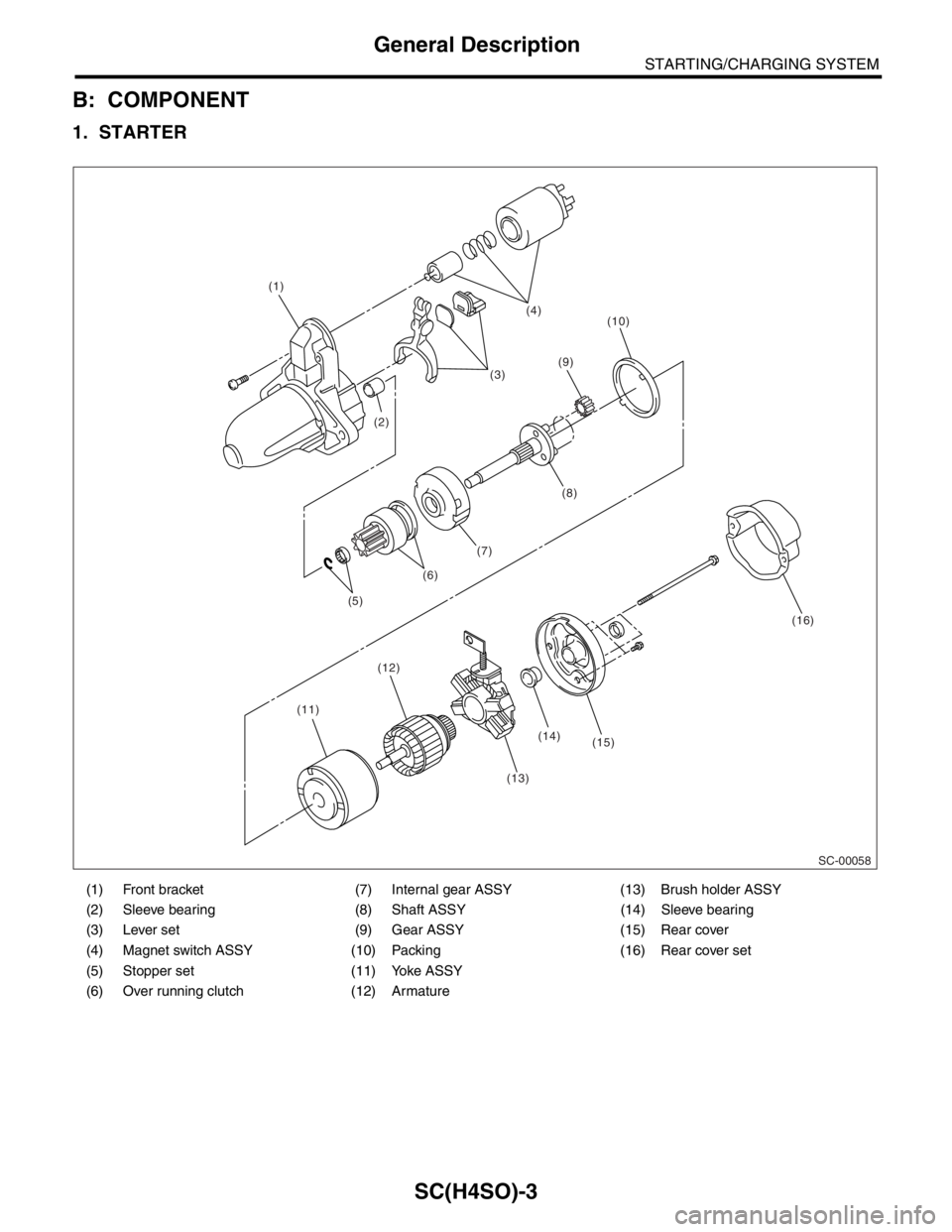
B: COMPONENT
1. STARTER
(1) Front bracket (7) Internal gear ASSY (13) Brush holder ASSY
(2) Sleeve bearing (8) Shaft ASSY (14) Sleeve bearing
(3) Lever set (9) Gear ASSY (15) Rear cover
(4) Magnet switch ASSY (10) Packing (16) Rear cover set
(5) Stopper set (11) Yoke ASSY
(6) Over running clutch (12) Armature
SC-00058
(14) (1)
(2)(3)(4)
(10)
(11)(12)
(13)(15)(16) (5)(6)(7)(8) (9)