2004 SUBARU FORESTER stop start
[x] Cancel search: stop startPage 1083 of 2870

SC(H4SO)-8
STARTING/CHARGING SYSTEM
Starter
7) Remove the plate.
8) Remove the shaft assembly and overrunning
clutch from front bracket as a unit.
NOTE:
Check the following points before removal.
Lever direction
Position of internal gear assembly
9) Remove the overrunning clutch from shaft as-
sembly as follows:
(1) Remove the stopper from ring by lightly tap-
ping the stopper with an appropriate tool (such
as a 14 mm (0.55 in) a fit socket wrench).(2) Remove the ring, stopper and clutch from
shaft.
(A) Plate
(A) Lever
(B) Shaft ASSY
(C) Overrunning clutch
(D) Internal gear ASSY
SC-00065
(A)
SC-00066
(A)
(D)
(C) (B)
(A) Socket wrench
(B) Ring
(C) Shaft
(D) Stopper
SC-00014
Page 1084 of 2870

SC(H4SO)-9
STARTING/CHARGING SYSTEM
Starter
D: ASSEMBLY
NOTE:
Apply grease to the following parts before assem-
bly.
Sleeve bearing
Pinion shaft rotational portion
Shaft spline portion
Inside of reduction system
Lever fulcrum/Clutch rotational portion
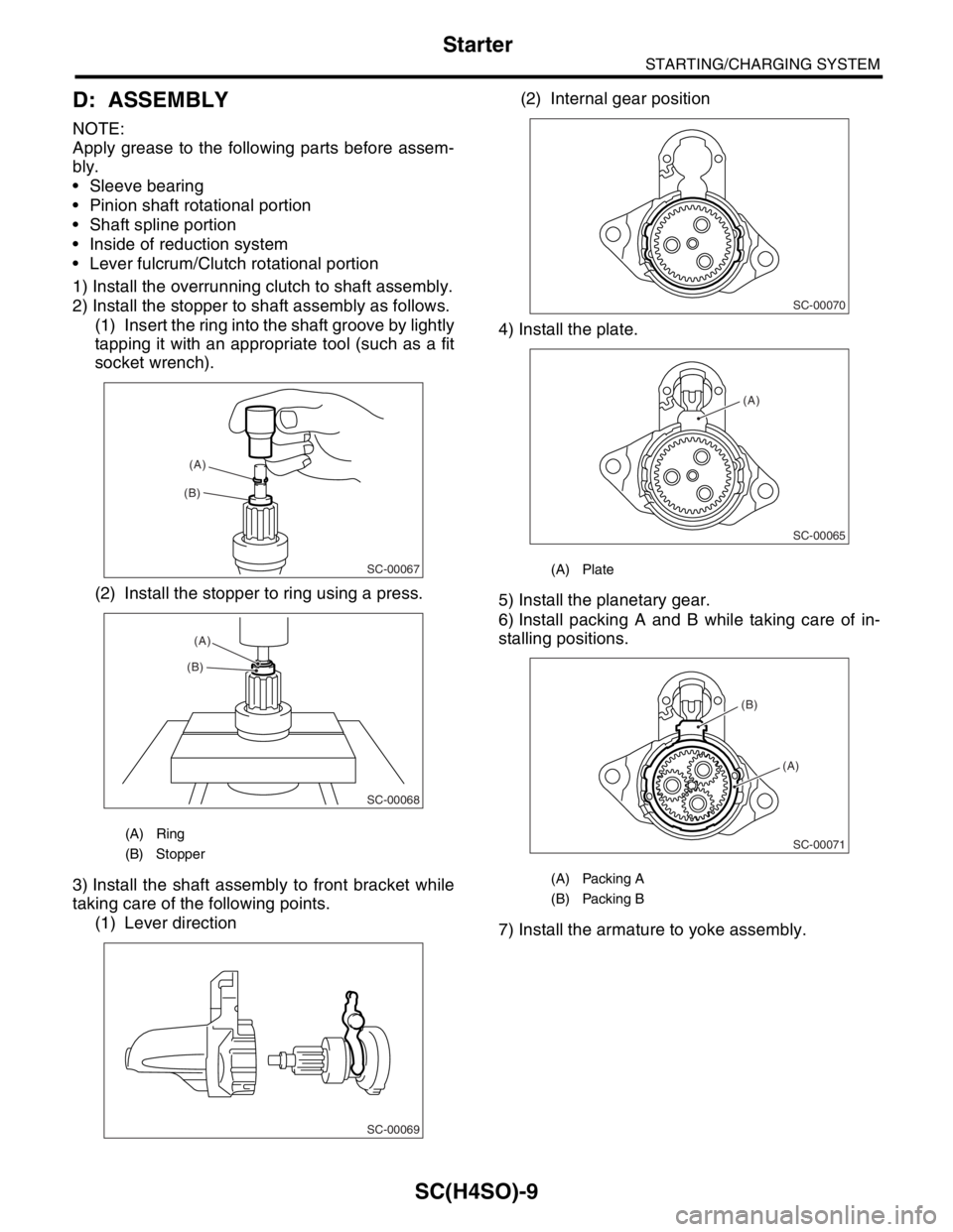
1) Install the overrunning clutch to shaft assembly.
2) Install the stopper to shaft assembly as follows.
(1) Insert the ring into the shaft groove by lightly
tapping it with an appropriate tool (such as a fit
socket wrench).
(2) Install the stopper to ring using a press.
3) Install the shaft assembly to front bracket while
taking care of the following points.
(1) Lever direction(2) Internal gear position
4) Install the plate.
5) Install the planetary gear.
6) Install packing A and B while taking care of in-
stalling positions.
7) Install the armature to yoke assembly.
(A) Ring
(B) Stopper
SC-00067
(B)(A)
SC-00068
(A)
(B)
SC-00069
(A) Plate
(A) Packing A
(B) Packing B
SC-00070
SC-00065
(A)
SC-00071
(A)
(B)
Page 1088 of 2870

SC(H4SO)-13
STARTING/CHARGING SYSTEM
Starter
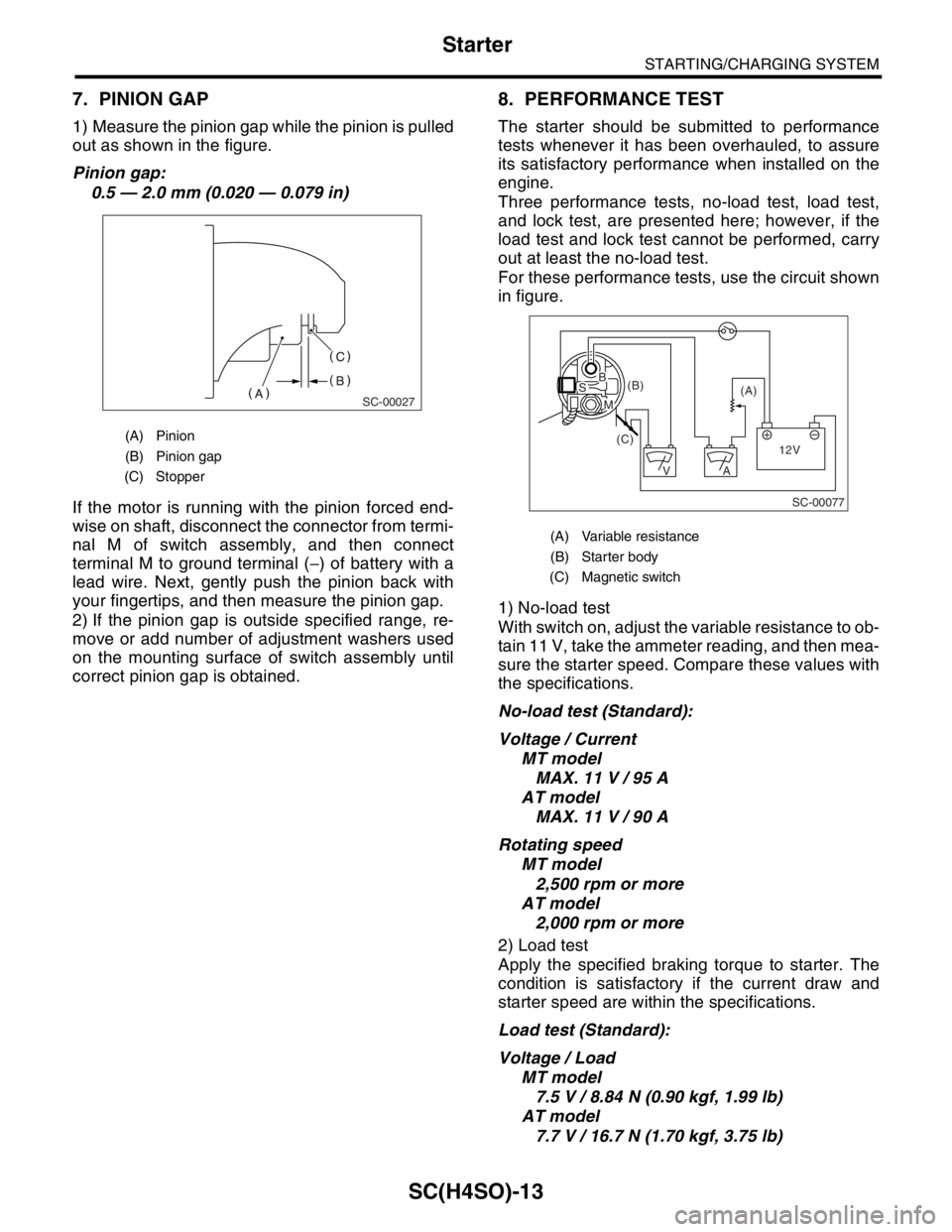
7. PINION GAP
1) Measure the pinion gap while the pinion is pulled
out as shown in the figure.
Pinion gap:
0.5 — 2.0 mm (0.020 — 0.079 in)
If the motor is running with the pinion forced end-
wise on shaft, disconnect the connector from termi-
nal M of switch assembly, and then connect
terminal M to ground terminal (−) of battery with a
lead wire. Next, gently push the pinion back with
your fingertips, and then measure the pinion gap.
2) If the pinion gap is outside specified range, re-
move or add number of adjustment washers used
on the mounting surface of switch assembly until
correct pinion gap is obtained.
8. PERFORMANCE TEST
The starter should be submitted to performance
tests whenever it has been overhauled, to assure
its satisfactory performance when installed on the
engine.
Three performance tests, no-load test, load test,
and lock test, are presented here; however, if the
load test and lock test cannot be performed, carry
out at least the no-load test.
For these performance tests, use the circuit shown
in figure.
1) No-load test
With switch on, adjust the variable resistance to ob-
tain 11 V, take the ammeter reading, and then mea-
sure the starter speed. Compare these values with
the specifications.
No-load test (Standard):
Voltage / Current
MT model
MAX. 11 V / 95 A
AT model
MAX. 11 V / 90 A
Rotating speed
MT model
2,500 rpm or more
AT model
2,000 rpm or more
2) Load test
Apply the specified braking torque to starter. The
condition is satisfactory if the current draw and
starter speed are within the specifications.
Load test (Standard):
Voltage / Load
MT model
7.5 V / 8.84 N (0.90 kgf, 1.99 lb)
AT model
7.7 V / 16.7 N (1.70 kgf, 3.75 lb)
(A) Pinion
(B) Pinion gap
(C) Stopper
SC-00027
(A) Variable resistance
(B) Starter body
(C) Magnetic switch
SC-00077
(A) (B)
(C)
12V +
AV
BS
M
Page 1105 of 2870

EN(H4SO)-7
ENGINE (DIAGNOSTIC)
General Description
The antenna feeder must be placed as far
apart as possible from the ECM and MFI har-
ness.
Carefully adjust the antenna for correct
matching.
When mounting a large power type radio, pay
special attention to the three items above men-
tioned.
Incorrect installation of the radio may affect
the operation of the ECM.
13) Before disconnecting the fuel hose, disconnect
the fuel pump connector and crank the engine for
more than five seconds to release pressure in the
fuel system. If engine starts during this operation,
run it until it stops.
14) Problems in the electronic-controlled automatic
transmission may be caused by failure of the en-
gine, the electronic control system, the transmis-
sion proper, or by a combination of these. These
three causes must be distinguished clearly when
performing diagnostics.
15) Diagnostics should be conducted by rotating
with simple, easy operations and proceeding to
complicated, difficult operations. The most impor-
tant thing in diagnostics is to understand the cus-
tomer’s complaint, and distinguish between the
three causes.
16) In AT models, do not continue the stall for more
than five seconds. (from closed throttle, fully open
throttle to stall engine speed.)
17) On the model with ABS, when performing driv-
ing test in jacked-up or lifted-up position, some-
times the warning light may be lit, but this is not a
malfunction of the system. The reason for this is the
speed difference between the front and rear
wheels. After diagnosis of engine control system,
perform the ABS memory clearance procedure of
self-diagnosis function.
B: INSPECTION
Before performing diagnostics, check the following
items which might affect engine problems:
1. BATTERY
1) Measure battery voltage and specific gravity of
electrolyte.
Standard voltage: 12 V
Specific gravity: Above 1.260
2) Check the condition of the main and other fuses,
and harnesses and connectors. Also check for
proper grounding.
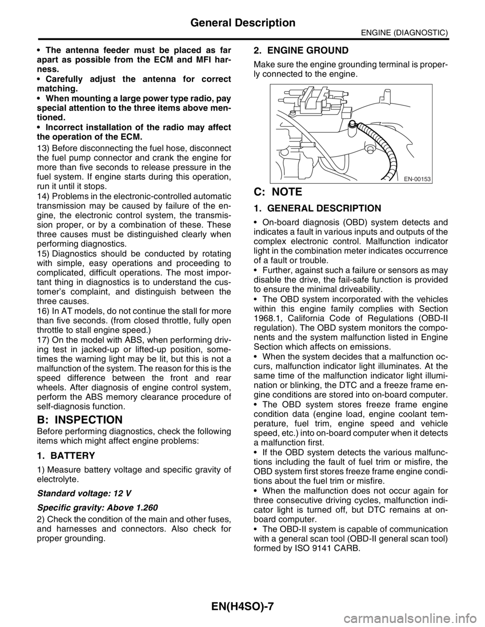
2. ENGINE GROUND
Make sure the engine grounding terminal is proper-
ly connected to the engine.
C: NOTE
1. GENERAL DESCRIPTION
On-board diagnosis (OBD) system detects and
indicates a fault in various inputs and outputs of the
complex electronic control. Malfunction indicator
light in the combination meter indicates occurrence
of a fault or trouble.
Further, against such a failure or sensors as may
disable the drive, the fail-safe function is provided
to ensure the minimal driveability.
The OBD system incorporated with the vehicles
within this engine family complies with Section
1968.1, California Code of Regulations (OBD-II
regulation). The OBD system monitors the compo-
nents and the system malfunction listed in Engine
Section which affects on emissions.
When the system decides that a malfunction oc-
curs, malfunction indicator light illuminates. At the
same time of the malfunction indicator light illumi-
nation or blinking, the DTC and a freeze frame en-
gine conditions are stored into on-board computer.
The OBD system stores freeze frame engine
condition data (engine load, engine coolant tem-
perature, fuel trim, engine speed and vehicle
speed, etc.) into on-board computer when it detects
a malfunction first.
If the OBD system detects the various malfunc-
tions including the fault of fuel trim or misfire, the
OBD system first stores freeze frame engine condi-
tions about the fuel trim or misfire.
When the malfunction does not occur again for
three consecutive driving cycles, malfunction indi-
cator light is turned off, but DTC remains at on-
board computer.
The OBD-II system is capable of communication
with a general scan tool (OBD-II general scan tool)
formed by ISO 9141 CARB.
EN-00153
Page 1140 of 2870

EN(H4SO)-42
ENGINE (DIAGNOSTIC)
Drive Cycle
13.Drive Cycle
A: OPERATION
There are three driving patterns on diagnosis. Fol-
lowing trouble can be diagnosed with driving spec-
ified patterns. After repair the following trouble, be
sure to check that the trouble is cleared correctly by
the driving specified patterns.
1. PREPARATION FOR DRIVE CYCLE
1) Check battery voltage is more than 12 V and fuel
remains half [20 — 402 (5.3 — 10.6 US gal, 4.4 —
8.8 Imp gal)].2) After clearing the memory, check for any remain-
ing unresolved trouble data.
3) Separate the test mode connector.
NOTE:
Be sure to perform the diagnosis after idling from
starting the cooled engine except when the engine
coolant temperature is specified.
Perform the diagnosis twice when the DTC is
marked with *. After the completion of first diagno-
sis, stop the engine and perform the second diag-
nosis on same condition.
2. DRIVE THE VEHICLE 20 MINUTES AT THE SPEED OF 80 KM/H (50 MPH), AND THEN IDLE
THE ENGINE 1 MINUTE.
3. 10 MINUTES IDLING
NOTE:
Drive the vehicle more than 4 km/h (6 MPH) before diagnosis.
DTC Item On condition
*P0030 HO2S Heater Control Circuit (Bank 1 Sensor 1) —
*P0111Intake Air Temperature Sensor Circuit Range/Per-
formance ProblemEngine coolant temperature at start is less than 30°C (86°F)
*P0125Insufficient coolant temperature for closed loop
fuel controlEngine coolant temperature at start is less than 20°C (68°F)
*P0130O
2 Sensor Circuit (Bank 1 Sensor 1)
—
*P0133O
2 Sensor Circuit Slow Response (Bank 1 Sensor
1)—
*P0420Catalyst System Efficiency Below Threshold
(Bank 1)—
P0459Evaporative Emission Control System Purge Con-
trol Valve Circuit High—
*P0461 Fuel Level Sensor Circuit Range/Performance —
*P0464 Fuel Level Sensor Circuit Intermittent —
*P1137O
2 Sensor Circuit (Bank 1 Sensor 1)
—
DTC Item On condition
*P0483 Cooling Fan Rationality Check —
*P0506 Idle Control System RPM Lower Than Expected —
*P0507 Idle Control System RPM Higher Than Expected —
Page 1488 of 2870

ME(H4DOTC)-32
MECHANICAL
Idle Speed
3. Idle Speed
A: INSPECTION
1. USING SUBARU SELECT MONITOR
1) Before checking the idle speed, check the fol-
lowing:
(1) Ensure the air cleaner element is free from
clogging, ignition timing is correct, spark plugs
are in good condition, and that the hoses are
connected properly.
(2) Ensure the malfunction indicator light does
not illuminate.
2) Warm-up the engine.
3) Stop the engine, and then turn the ignition switch
to OFF.
4) Insert the cartridge to Subaru Select Monitor.
5) Connect the Subaru Select Monitor to data link
connector.
6) Turn the ignition switch to ON, and Subaru Se-
lect Monitor switch to ON.
7) Select the {2. Each System Check} in Main
Menu.
8) Select the {Engine Control System} in Selection
Menu.
9) Select the {1. Current Data Display & Save} in
Engine Control System Diagnosis.
10) Select the {1.12 Data Display} in Data Display
Menu.
11) Start the engine, and then read the engine idle
speed.
12) Check the idle speed when unloaded. (With
headlights, heater fan, rear defroster, radiator fan,
air conditioning, etc. OFF)
Idle speed [No load and gears in neutral]:
700
±100 rpm
13) Check the idle speed when loaded. (Turn the
air conditioning switch to “ON” and operate the
compressor for at least 1 minute before measure-
ment.)
Idle speed [A/C “ON”, no load and gears in neu-
tral]:
A/C Refrigerant pressure (LOW)
MT: 725
±100 rpm
AT: 750
±100 rpm
A/C Refrigerant pressure (HIGH)
MT: 800
±100 rpm
AT: 825
±100 rpm
NOTE:
As idle speed is controlled by the automatic adjust-
ment type, it can not be adjusted manually. If the
idle speed is out of specifications, refer to General
On-board Diagnosis Table under “Engine Control
System”.
Page 1489 of 2870

ME(H4DOTC)-33
MECHANICAL
Ignition Timing
4. Ignition Timing
A: INSPECTION
1. USING SUBARU SELECT MONITOR
1) Before checking the ignition timing speed, check
the following:
(1) Ensure the air cleaner element is free from
clogging, spark plugs are in good condition, and
that hoses are connected properly.
(2) Ensure the malfunction indicator light does
not illuminate.
2) Warm-up the engine.
3) Stop the engine, and then turn the ignition switch
to OFF.
4) Insert the cartridge to Subaru Select Monitor.
5) Connect the Subaru Select Monitor to data link
connector.
6) Turn the ignition switch to ON, and Subaru Se-
lect Monitor switch to ON.
7) Select the {2. Each System Check} in Main
Menu.
8) Select the {Engine Control System} in Selection
Menu.
9) Select the {1. Current Data Display & Save} in
Engine Control System Diagnosis.
10) Select the {1.12 Data Display} in Data Display
Menu.
11) Start the engine and check the ignition timing at
idle speed.
Ignition timing [BTDC/rpm]:
2.0 L model
12
°±10°/700
2.5 L model
17
°±10°/700
If the timing is not correct, check the ignition control
system. Refer to Engine Control System.
Page 1503 of 2870

ME(H4DOTC)-45
MECHANICAL
Engine Assembly
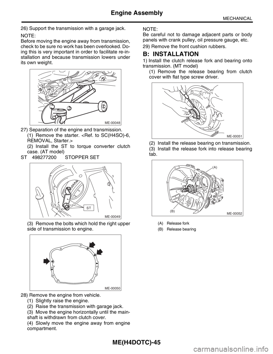
26) Support the transmission with a garage jack.
NOTE:
Before moving the engine away from transmission,
check to be sure no work has been overlooked. Do-
ing this is very important in order to facilitate re-in-
stallation and because transmission lowers under
its own weight.
27) Separation of the engine and transmission.
(1) Remove the starter.
(2) Install the ST to torque converter clutch
case. (AT model)
ST 498277200 STOPPER SET
(3) Remove the bolts which hold the right upper
side of transmission to engine.
28) Remove the engine from vehicle.
(1) Slightly raise the engine.
(2) Raise the transmission with garage jack.
(3) Move the engine horizontally until the main-
shaft is withdrawn from clutch cover.
(4) Slowly move the engine away from engine
compartment.NOTE:
Be careful not to damage adjacent parts or body
panels with crank pulley, oil pressure gauge, etc.
29) Remove the front cushion rubbers.
B: INSTALLATION
1) Install the clutch release fork and bearing onto
transmission. (MT model)
(1) Remove the release bearing from clutch
cover with flat type screw driver.
(2) Install the release bearing on transmission.
(3) Install the release fork into release bearing
tab.
ME-00048
ST
ME-00049
ME-00050
(A) Release fork
(B) Release bearing
ME-00051
ME-00052
(A)
(B)