2004 SUBARU FORESTER stop start
[x] Cancel search: stop startPage 1505 of 2870

ME(H4DOTC)-47
MECHANICAL
Engine Assembly
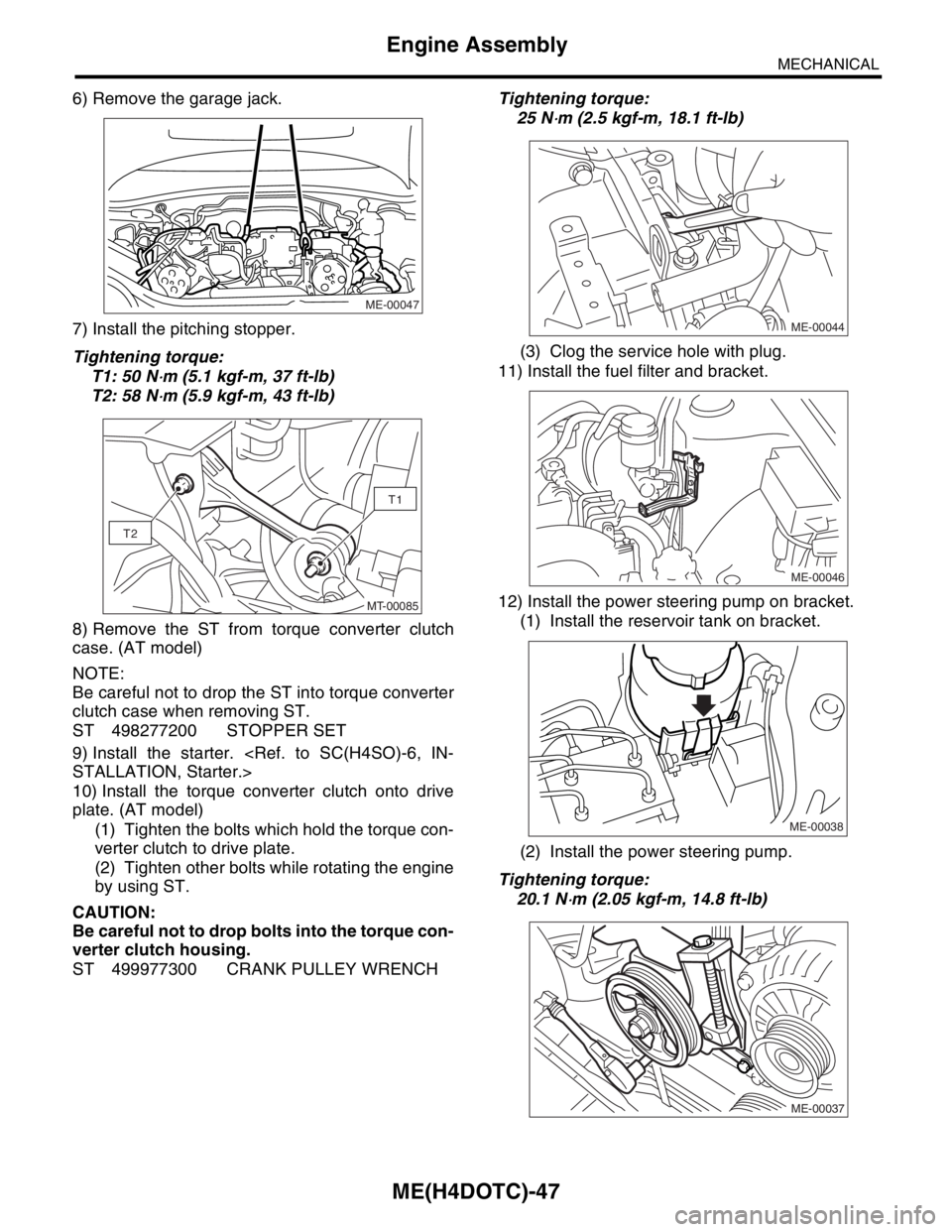
6) Remove the garage jack.
7) Install the pitching stopper.
Tightening torque:
T1: 50 N
⋅m (5.1 kgf-m, 37 ft-lb)
T2: 58 N
⋅m (5.9 kgf-m, 43 ft-lb)
8) Remove the ST from torque converter clutch
case. (AT model)
NOTE:
Be careful not to drop the ST into torque converter
clutch case when removing ST.
ST 498277200 STOPPER SET
9) Install the starter.
10) Install the torque converter clutch onto drive
plate. (AT model)
(1) Tighten the bolts which hold the torque con-
verter clutch to drive plate.
(2) Tighten other bolts while rotating the engine
by using ST.
CAUTION:
Be careful not to drop bolts into the torque con-
verter clutch housing.
ST 499977300 CRANK PULLEY WRENCHTightening torque:
25 N
⋅m (2.5 kgf-m, 18.1 ft-lb)
(3) Clog the service hole with plug.
11) Install the fuel filter and bracket.
12) Install the power steering pump on bracket.
(1) Install the reservoir tank on bracket.
(2) Install the power steering pump.
Tightening torque:
20.1 N
⋅m (2.05 kgf-m, 14.8 ft-lb)
ME-00047
T1
T2
MT-00085ME-00044
ME-00046
ME-00038
ME-00037
Page 1637 of 2870

EN(H4DOTC)-7
ENGINE (DIAGNOSTIC)
General Description
12) Observe the following cautions when installing
a radio in MFI equipped models.
CAUTION:
The antenna must be kept as far apart as pos-
sible from the control unit. (The ECM is located
under the steering column, inside of the instru-
ment panel lower trim panel.)
The antenna feeder must be placed as far
apart as possible from the ECM and MFI har-
ness.
Carefully adjust the antenna for correct
matching.
When mounting a large power type radio, pay
special attention to the three items above men-
tioned.
Incorrect installation of the radio may affect
the operation of the ECM.
13) Before disconnecting the fuel hose, disconnect
the fuel pump connector and crank the engine for
more than five seconds to release pressure in the
fuel system.If engine starts during this operation,
run it until it stops.
14) Problems in the electronic-controlled automatic
transmission may be caused by failure of the en-
gine, the electronic control system, the transmis-
sion proper, or by a combination of these.These
three causes (engine, electronic control system,
transmission) must be distinguished clearly when
performing diagnostics.
15) Diagnostics should be conducted by rotating
with simple, easy operations and proceeding to
complicated, difficult operations.The most impor-
tant thing in diagnostics is to understand the cus-
tomer’s complaint, and distinguish between the
three causes.
16) On the model with ABS, when performing driv-
ing test in jacked-up or lifted-up position, some-
times the warning light may be lit, but this is not a
malfunction of the system.The reason for this is the
speed difference between the front and rear
wheels.After diagnosis of engine control system,
perform the ABS memory clearance procedure of
self-diagnosis function.
B: INSPECTION
Before performing diagnostics, check the following
items which might affect engine problems:
1. BATTERY
1) Measure battery voltage and specific gravity of
electrolyte.
Standard voltage: 12 V
Specific gravity: Above 1.2602) Check the condition of the main and other fuses,
and harnesses and connectors.Also check for
proper grounding.
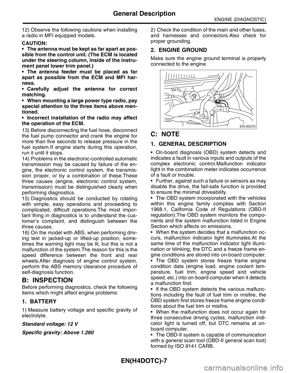
2. ENGINE GROUND
Make sure the engine ground terminal is properly
connected to the engine.
C: NOTE
1. GENERAL DESCRIPTION
On-board diagnosis (OBD) system detects and
indicates a fault in various inputs and outputs of the
complex electronic control.Malfunction indicator
light in the combination meter indicates occurrence
of a fault or trouble.
Further, against such a failure or sensors as may
disable the drive, the fail-safe function is provided
to ensure the minimal driveability.
The OBD system incorporated with the vehicles
within this engine family complies with Section
1968.1, California Code of Regulations (OBD-II
regulation).The OBD system monitors the compo-
nents and the system malfunction listed in Engine
Section which affects on emissions.
When the system decides that a malfunction oc-
curs, malfunction indicator light illuminates.At the
same time of the malfunction indicator light illumi-
nation or blinking, the DTC and a freeze frame en-
gine conditions are stored into on-board computer.
The OBD system stores freeze frame engine
condition data (engine load, engine coolant tem-
perature, fuel trim, engine speed and vehicle
speed, etc.) into on-board computer when it detects
a malfunction first.
If the OBD system detects the various malfunc-
tions including the fault of fuel trim or misfire, the
OBD system first stores freeze frame engine condi-
tions about the fuel trim or misfire.
When the malfunction does not occur again for
three consecutive driving cycles, malfunction indi-
cator light is turned off, but DTC remains at on-
board computer.
The OBD-II system is capable of communication
with a general scan tool (OBD-II general scan tool)
formed by ISO 9141 CARB.
EN-00070
Page 1675 of 2870

EN(H4DOTC)-45
ENGINE (DIAGNOSTIC)
Drive Cycle
13.Drive Cycle
A: OPERATION
There are three driving patterns on diagnosis.Following trouble can be diagnosed with driving specified pat-
terns.After repair the following trouble, be sure to check that the trouble is cleared correctly by the driving
specified patterns.
1. PREPARATION FOR DRIVE CYCLE
1) Check battery voltage is more than 12 V and fuel remains half [20 — 402 (5.3 — 10.6 US gal, 4.4 — 8.8
Imp gal)].
2) After performing the diagnostics and clearing the memory, check for any remaining unresolved trouble da-
ta.
3) Separate the test mode connector.
NOTE:
Be sure to perform the diagnosis after idling from starting the cooled engine except when the engine cool-
ant temperature is specified.
Perform the diagnosis twice when the DTC is marked * and after the completion of first diagnosis, stop the
engine and perform the second diagnosis in the same condition.
2. DRIVE THE VEHICLE 20 MINUTES AT THE SPEED OF 80 KM/H (50 MPH), AND THEN IDLE
THE ENGINE 1 MINUTE.
3. 10 MINUTES IDLING
NOTE:
Drive the vehicle more than 10 km/h (6 MPH) before diagnosis.
DTC Item On condition
*P0125 Insufficient Coolant Temperature For Closed Loop Fuel ControlEngine coolant temperature at
start is less than 20°C (68°F)
*P0133O
2 Sensor Circuit Slow Response (Bank 1 Sensor 1)
—
*P0420 Catalyst System Efficiency Below Threshold (Bank 1) —
P0459 Evaporative Emission Control System Purge Control Valve Circuit High —
P0461 Fuel Level Sensor Circuit Range/Performance —
P0546 Exhaust Gas Temperature Sensor Circuit High - Bank 1 —
P1312 Exhaust Gas Temperature Sensor MalfunctionEngine coolant temperature at
start is less than 30°C (86°F)
DTC Item On condition
P0111 Intake Air Temperature Circuit Range/Performance —
P0464 Fuel Level Sensor Circuit Intermittent —
P0508 Idle Control System Circuit Low —
*P0483 Cooling Fan Rationality Check —
*P0506 Idle Control System RPM Lower Than Expected —
*P0507 Idle Control System RPM Higher Than Expected —
Page 1676 of 2870

EN(H4DOTC)-46
ENGINE (DIAGNOSTIC)
Drive Cycle
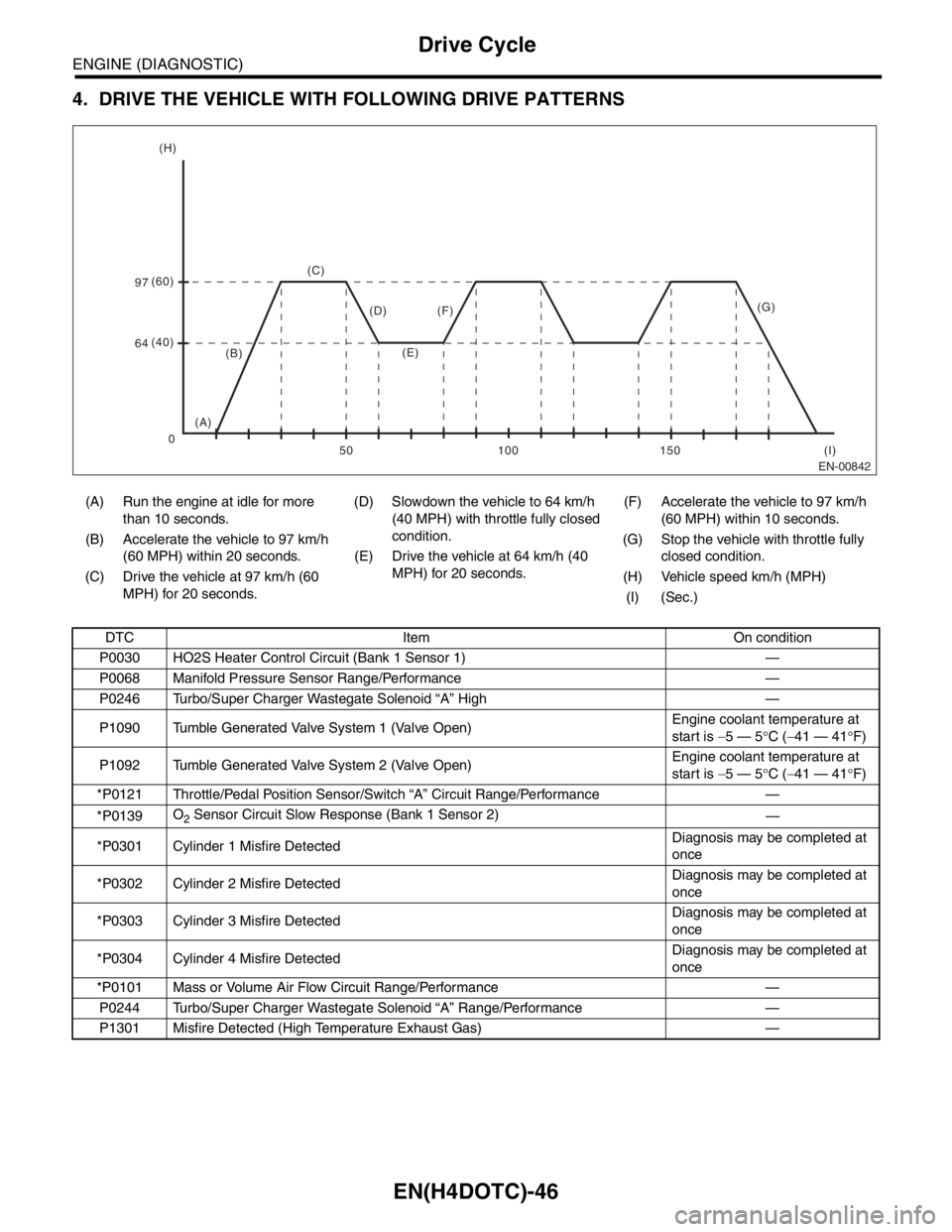
4. DRIVE THE VEHICLE WITH FOLLOWING DRIVE PATTERNS
(A) Run the engine at idle for more
than 10 seconds.(D) Slowdown the vehicle to 64 km/h
(40 MPH) with throttle fully closed
condition.(F) Accelerate the vehicle to 97 km/h
(60 MPH) within 10 seconds.
(B) Accelerate the vehicle to 97 km/h
(60 MPH) within 20 seconds.(G) Stop the vehicle with throttle fully
closed condition. (E) Drive the vehicle at 64 km/h (40
MPH) for 20 seconds.
(C) Drive the vehicle at 97 km/h (60
MPH) for 20 seconds.(H) Vehicle speed km/h (MPH)
(I) (Sec.)
DTC Item On condition
P0030 HO2S Heater Control Circuit (Bank 1 Sensor 1) —
P0068 Manifold Pressure Sensor Range/Performance —
P0246 Turbo/Super Charger Wastegate Solenoid “A” High —
P1090 Tumble Generated Valve System 1 (Valve Open)Engine coolant temperature at
start is −5 — 5°C (−41 — 41°F)
P1092 Tumble Generated Valve System 2 (Valve Open)Engine coolant temperature at
start is −5 — 5°C (−41 — 41°F)
*P0121 Throttle/Pedal Position Sensor/Switch “A” Circuit Range/Performance —
*P0139O
2 Sensor Circuit Slow Response (Bank 1 Sensor 2)
—
*P0301 Cylinder 1 Misfire DetectedDiagnosis may be completed at
once
*P0302 Cylinder 2 Misfire DetectedDiagnosis may be completed at
once
*P0303 Cylinder 3 Misfire DetectedDiagnosis may be completed at
once
*P0304 Cylinder 4 Misfire DetectedDiagnosis may be completed at
once
*P0101 Mass or Volume Air Flow Circuit Range/Performance —
P0244 Turbo/Super Charger Wastegate Solenoid “A” Range/Performance —
P1301 Misfire Detected (High Temperature Exhaust Gas) —
EN-00842
(C) (H)
(I) (60)
97
64(40)
(B)
(A)(F) (D)
(E)
150 100 50 0(G)
Page 2029 of 2870

EN(H4DOTC 2.5)-5
ENGINE (DIAGNOSTIC)
General Description
3. General Description
A: CAUTION
1) Airbag system wiring harness is routed near the
ECM, main relay and fuel pump relay.
CAUTION:
All airbag system wiring harness and con-
nectors are all colored yellow. Do not use the
electrical test equipment on these circuits.
Be careful not to damage the Airbag system
wiring harness when servicing the ECM, TCM,
main relay and fuel pump relay.
2) Never connect the battery in reverse polarity.
The ECM will be destroyed immediately.
The fuel injector and other part will be damaged.
3) Do not disconnect the battery terminals while the
engine is running.
A large counter electromotive force will be gener-
ated in the generator, and this voltage may damage
electronic parts such as ECM, etc.
4) Before disconnecting the connectors of each
sensor and the ECM, be sure to turn OFF the igni-
tion switch.
5) Poor contact has been identified as a primary
cause of this problem. Measure the voltage or re-
sistance of individual sensor or all electrical control
modules using a tapered pin with a diameter of less
than 0.64 mm (0.025 in). Do not insert the pin more
than 5 mm (0.20 in) into the part.
6) Remove the ECM from the located position after
disconnecting two cables on battery.
Otherwise, the ECM may be damaged.
CAUTION:
When replacing the ECM, be careful not to use
the wrong spec. ECM to avoid damaging the
fuel injection system.
7) Connectors to each sensor in the engine com-
partment and the harness connectors on the en-
gine side and body side are all designed to be
waterproof. However, take care not to allow water
to get into the connectors when washing the vehi-
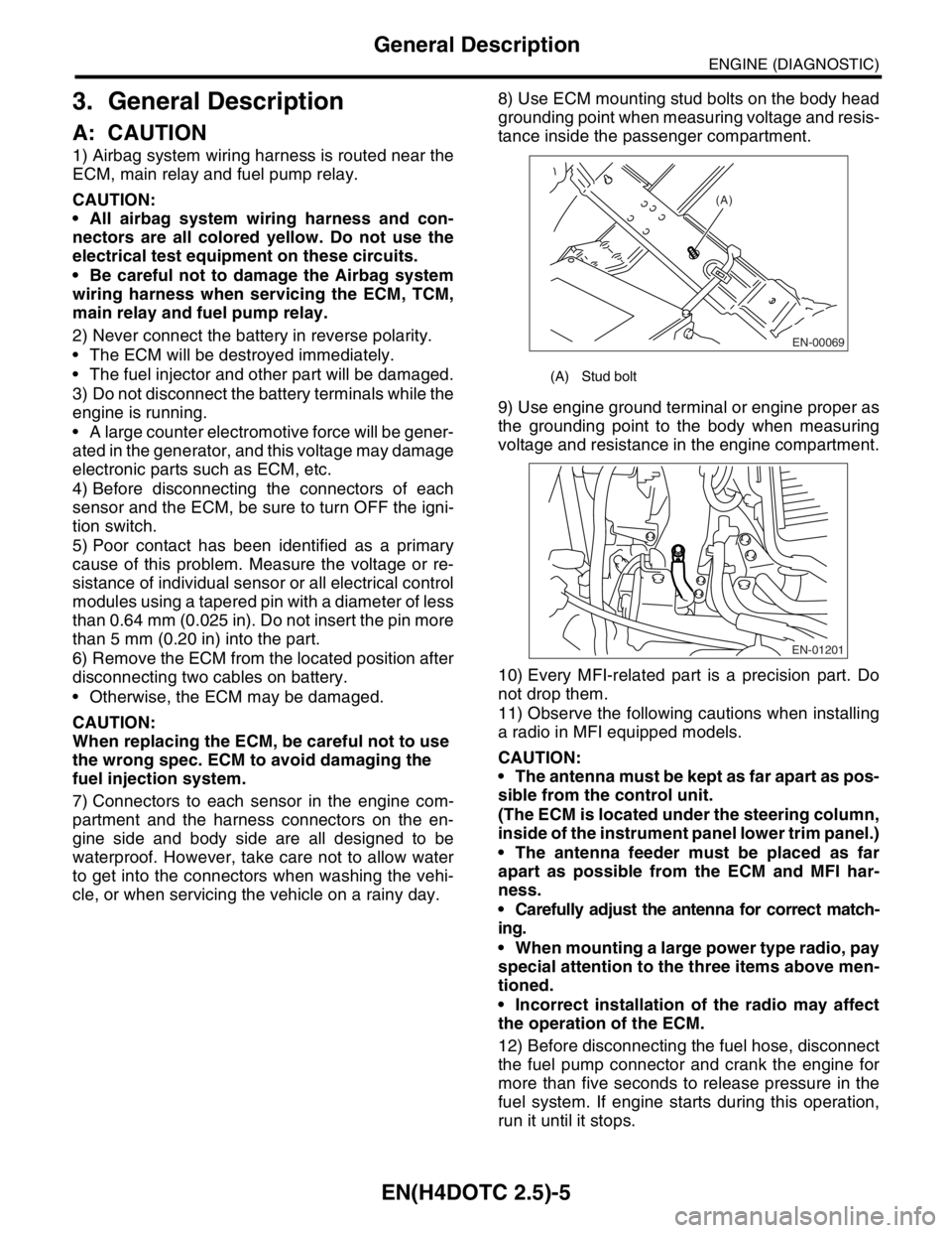
cle, or when servicing the vehicle on a rainy day. 8) Use ECM mounting stud bolts on the body head
grounding point when measuring voltage and resis-
tance inside the passenger compartment.
9) Use engine ground terminal or engine proper as
the grounding point to the body when measuring
voltage and resistance in the engine compartment.
10) Every MFI-related part is a precision part. Do
not drop them.
11) Observe the following cautions when installing
a radio in MFI equipped models.
CAUTION:
The antenna must be kept as far apart as pos-
sible from the control unit.
(The ECM is located under the steering column,
inside of the instrument panel lower trim panel.)
The antenna feeder must be placed as far
apart as possible from the ECM and MFI har-
ness.
Carefully adjust the antenna for correct match-
ing.
When mounting a large power type radio, pay
special attention to the three items above men-
tioned.
Incorrect installation of the radio may affect
the operation of the ECM.
12) Before disconnecting the fuel hose, disconnect
the fuel pump connector and crank the engine for
more than five seconds to release pressure in the
fuel system. If engine starts during this operation,
run it until it stops.
(A) Stud bolt
EN-00069
(A)
EN-01201
Page 2053 of 2870

EN(H4DOTC 2.5)-29
ENGINE (DIAGNOSTIC)
Subaru Select Monitor
NOTE:
For detailed operation procedure, refer to the “SUBARU SELECT MONITOR OPERATION MANUAL”.
Mass air flow sensor signal Air Flow Sensor Voltage V
AT/MT identification signal AT Vehicle ID Signal ON or OFF
ETC motor relay ETC Motor Relay ON or OFF
Clutch SW Clutch Switch ON or OFF
Stop Light SW Stop Light Switch ON or OFF
SET/COAST SW SET/COAST Switch ON or OFF
RESUME/ACCEL SW RESUME/ACCEL Switch ON or OFF
Brake SW Brake Switch ON or OFF
Main SW Main Switch ON or OFF
Ignition switch signal Ignition Switch ON or OFF
Test Mode Signal Test Mode Signal ON or OFF
Neutral position switch signal Neutral Position Switch ON or OFF
Air conditioning switch signal A/C Switch ON or OFF
Air conditioning signal A/C Compressor Signal ON or OFF
Radiator main fan relay signal Radiator Fan Relay #1 ON or OFF
Knocking signal Knocking Signal ON or OFF
Radiator sub fan relay signal Radiator Fan Relay #2 ON or OFF
Power steering switch signal P/S Switch ON or OFF
Rear oxygen sensor rich signalRear O
2 Rich Signal
ON or OFF
Starter switch signal Starter Switch ON or OFF
Idle switch signal Idle Switch Signal ON or OFF
Crankshaft position sensor signal Crankshaft Position Sig. ON or OFF
Camshaft position sensor signal Camshaft Position Sig. ON or OFF
Rear defogger switch signal Rear Defogger SW ON or OFF
Blower fan switch signal Blower Fan SW ON or OFF
Small light switch signal Light Switch ON or OFF
Handle switch signal Handle Switch —
Wiper switch signal Wiper Switch ON or OFF
A/C mid pressure switch signal A/C mid Pressure Switch ON or OFF
AT coordinate retard angle demand Retard Signal form AT ON or OFF
AT coordinate fuel cut demand Fuel Cut Signal from AT ON or OFF
AT coordinate permission signal Torque Permission Signal ON or OFF
UDC not torque down output Ban of Torque Down ON or OFF
UDC torque down demand Request Torque Down UDC ON or OFF
Tumble generated valve output signal TGV Output ON or OFF
Tumble generated valve drive signal TGV Drive OPEN or CLOSERemarks Display Unit of measure
Page 2056 of 2870
![SUBARU FORESTER 2004 Service Repair Manual EN(H4DOTC 2.5)-32
ENGINE (DIAGNOSTIC)
Subaru Select Monitor
7. LED OPERATION MODE FOR ENGINE
1) On the «Main Menu» display screen, select the {Each System Check} and press the [YES] key.
2) On the � SUBARU FORESTER 2004 Service Repair Manual EN(H4DOTC 2.5)-32
ENGINE (DIAGNOSTIC)
Subaru Select Monitor
7. LED OPERATION MODE FOR ENGINE
1) On the «Main Menu» display screen, select the {Each System Check} and press the [YES] key.
2) On the �](/manual-img/17/57426/w960_57426-2055.png)
EN(H4DOTC 2.5)-32
ENGINE (DIAGNOSTIC)
Subaru Select Monitor
7. LED OPERATION MODE FOR ENGINE
1) On the «Main Menu» display screen, select the {Each System Check} and press the [YES] key.
2) On the «System Selection Menu» display screen, select the {Engine} and press the [YES] key.
3) Press the [YES] key after the information of engine type was displayed.
4) On the «Engine Diagnosis» screen, select the {Current Data Display/Save}, and then press the [YES] key.
5) On the «Data Display» screen, select the {Data & LED Display} and press the [YES] key.
6) Using the scroll key, move the display screen up or down until the desired data is shown.
A list of the support data is shown in the following table.
Description Display Message LED “ON” requirements
Ignition switch signal Ignition Switch ON or OFF When ignition switch is ON.
Test Mode Signal Test Mode Signal ON or OFF When test mode connector is connected.
Neutral position switch signal Neutral Position Switch ON or OFF When neutral position signal is entered.
Air conditioning switch signal A/C Switch ON or OFF When air conditioning switch is ON.
Air conditioning relay signal A/C Compressor Signal ON or OFF When air conditioning relay is in function.
Radiator main fan relay signal Radiator Fan Relay #1 ON or OFF When radiator main fan relay is in function.
Knocking signal Knocking Signal ON or OFF When knocking signal is input.
Radiator sub fan relay signal Radiator Fan Relay #2 ON or OFF When radiator sub fan relay is in function.
Rear oxygen sensor rich signalRear O
2 Rich Signal
ON or OFFWhen rear oxygen sensor mixture ratio is
rich.
Starter switch signal Starter Switch Signal ON or OFF When starter switch signal is entered.
Idle switch signal Idle Switch Signal ON or OFF When idle switch signal is entered.
Crankshaft position sensor signal Crankshaft Position Signal ON or OFFWhen crankshaft position sensor signal is
input.
Camshaft position sensor signal Camshaft Position Signal ON or OFFWhen camshaft position sensor signal is
entered.
Power steering switch signal P/S Switch ON or OFF When power steering switch is entered.
Rear defogger switch signal Rear Defogger Switch ON or OFF When rear defogger switch is ON.
Blower fan switch signal Blower Fan Switch ON or OFF When blower fan switch is ON.
Small light switch signal Light Switch ON or OFF When small light switch is ON.
Tumble generated valve actuator
signalTGV Output ON or OFF When TGV actuator signal is entered.
Tumble generated valve drive sig-
nalTGV DriveClose or
OpenWhen TGV moves and valve opens.
Handle switch signal Handle SWLow Input
or High
InputIlluminates in Low Input.
AT/MT identification terminal AT Vehicle ID Signal ON or OFF ON (AT model).
Wiper switch signal Wiper Switch ON or OFF When wiper switch is turned to ON.
A/C mid pressure switch signal A/C Mid Pressure Switch ON or OFFWhen A/C mid pressure switch is turned to
ON.
AT coordinate retard angle
demandRetard Signal from AT ON or OFF When AT retard angle signal is exists.
AT coordinate fuel cut demand Fuel Cut Signal from AT ON or OFFWhen AT coordinate fuel cut demand signal
is exists.
AT coordinate permission signal Torque Permission Signal ON or OFFWhen AT coordinate permission signal is
exists.
VDC not torque down out put Ban of Torque Down ON or OFFWhen VDC not torque down output signal is
exists.
VDC torque down demand Request Torque Down VDC ON or OFFWhen VDC torque down demand signal is
exists.
ETC motor relay signal ETC Motor Relay ON or OFFWhen electronic throttle control relay is in
function.
Clutch switch signal Clutch Switch ON or OFF When clutch switch is ON.
Stop switch signal Stop Light Switch ON or OFF When stop light switch is ON.
Page 2060 of 2870

EN(H4DOTC 2.5)-36
ENGINE (DIAGNOSTIC)
Inspection Mode
P0852 Neutral Switch Input Circuit High —
P1086 Tumble Generated Valve Position Sensor 2 Circuit Low —
P1087 Tumble Generated Valve Position Sensor 2 Circuit High —
P1088 Tumble Generated Valve Position Sensor 1 Circuit Low —
P1089 Tumble Generated Valve Position Sensor 1 Circuit High —
P1091 Tumble Generated Valve System 1 (Valve Close) —
P1093 Tumble Generated Valve System 2 (Valve Close) —
P1094 Tumble Generated Valve Signal 1 Circuit Malfunction (Open) —
P1095 Tumble Generated Valve Signal 1 Circuit Malfunction (Short) —
P1096 Tumble Generated Valve Signal 2 Circuit Malfunction (Open) —
P1097 Tumble Generated Valve Signal 2 Circuit Malfunction (Short) —
P1110 Atmospheric Pressure Sensor Circuit Malfunction (Low Input) —
P1111 Atmospheric Pressure Sensor Circuit Malfunction (High Input) —
P1160 Return Spring Failure—
P1518 Starter Switch Circuit Low Input —
P1544 High exhaust temperature detected —
P1560 Back-Up Voltage Circuit Malfunction —
P1570 ANTENNA—
P1571 Reference Code Incompatibility —
P1572 IMM Circuit Failure (Except Antenna Circuit) —
P1574 Key Communication Failure —
P1576 EGI Control Module EEPROM —
P1577 IMM Control Module EEPROM —
P2088 OCV Solenoid Valve Signal A Circuit Open (Bank 1) —
P2089 OCV Solenoid Valve Signal A Circuit Short (Bank 1) —
P2092 OCV Solenoid Valve Signal A Circuit Open (Bank 2) —
P2093 OCV Solenoid Valve Signal A Circuit Short (Bank 2) —
P2101 Throttle Actuator Control Motor Circuit Range/Performance —
P2102 Throttle Actuator Control Motor Circuit Low —
P2103 Throttle Actuator Control Motor Circuit High —
P2109 Throttle/Pedal Position Sensor A Minimum Stop Performance —
P2122 Throttle/Pedal Position Sensor/Switch “D” Circuit Low Input —
P2123 Throttle/Pedal Position Sensor/Switch “D” Circuit High Input —
P2127 Throttle/Pedal Position Sensor/Switch “E” Circuit Low Input —
P2128 Throttle/Pedal Position Sensor/Switch “E” Circuit High Input —
P2135 Throttle/Pedal Position Sensor/Switch “A”/“B” Voltage Rationality —
P2138 Throttle/Pedal Position Sensor/Switch “D”/“E” Voltage Rationality —DTC Item On condition