2004 SUBARU FORESTER compression ratio
[x] Cancel search: compression ratioPage 1244 of 2870

EN(H4SO)-146
ENGINE (DIAGNOSTIC)
Diagnostic Procedure with Diagnostic Trouble Code (DTC)
16 CHECK MISFIRE SYMPTOM.
1) Turn the ignition switch to ON.
2) READ DTC.
Subaru Select Monitor
OBD-II scan tool
For detailed operation procedures, refer to the
OBD-II General Scan Tool Operation Manual.
N
OTE:
Perform diagnosis according to the items listed
below.Does the Subaru Select Moni-
tor or OBD-II general scan tool
indicate a DTC?Go to step 21.Go to step 17.
17 CHECK ANY OTHER DTC ON DISPLAY.Is DTC P0301 and P0302 dis-
played?Go to step 22.Go to step 18.
18 CHECK ANY OTHER DTC ON DISPLAY.Is DTC P0303 and P0304 dis-
played?Go to step 23.Go to step 19.
19 CHECK ANY OTHER DTC ON DISPLAY.Is DTC P0301 and P0303 dis-
played?Go to step 24.Go to step 20.
20 CHECK ANY OTHER DTC ON DISPLAY.Is DTC P0302 and P0304 dis-
played?Go to step 25.Go to step 26.
21 ONLY ONE CYLINDER.Is there a fault in that cylinder? Repair or replace
the faulty par t.
N
OTE:
Check the follow-
ing items:
Spark plug
Spark plug cord
Fuel injector
Compression
ratioGo to DTC P0171.
DTC P0171 SYS-
TEM TOO LEAN
(BANK 1), Diag-
nostic Procedure
with Diagnostic
Trouble Code
(DTC).>
22 GROUP OF #1 AND #2 CYLINDERS.Are there faults in #1 and #2
cylinders?Repair or replace
the faulty par t.
N
OTE:
Check the fol-
lowing items:
Spark plug
Fuel injector
Ignition coil
Compres-
sion ratio
If no abnormal is
discovered, check
for “IGNITION
CONTROL SYS-
TEM” of #1 and #2
cylinders side.
IGNITION CON-
TROL SYSTEM,
Diagnostics for
Engine Starting
Fa il u r e. >Go to DTC P0171.
DTC P0171 SYS-
TEM TOO LEAN
(BANK 1), Diag-
nostic Procedure
with Diagnostic
Trouble Code
(DTC).> Step Check Yes No
Page 1245 of 2870

EN(H4SO)-147
ENGINE (DIAGNOSTIC)
Diagnostic Procedure with Diagnostic Trouble Code (DTC)
23 GROUP OF #3 AND #4 CYLINDERS.Are there faults in #3 and #4
cylinders?Repair or replace
the faulty par t.
N
OTE:
Check the fol-
lowing items:
Spark plug
Fuel injector
Ignition coil
If no abnormal is
discovered, check
for “16. D: IGNI-
TION CONTROL
SYSTEM” of #3
and #4 cylinders
side.
IGNITION CON-
TROL SYSTEM,
Diagnostics for
Engine Starting
Fa il u r e. >Go to DTC P0171.
DTC P0171 SYS-
TEM TOO LEAN
(BANK 1), Diag-
nostic Procedure
with Diagnostic
Trouble Code
(DTC).>
24 GROUP OF #1 AND #3 CYLINDERS.Are there faults in #1 and #3
cylinders?Repair or replace
the faulty par t.
N
OTE:
Check the follow-
ing items:
Spark plug
Fuel injector
Skipping timing
belt teethGo to DTC P0171.
DTC P0171 SYS-
TEM TOO LEAN
(BANK 1), Diag-
nostic Procedure
with Diagnostic
Trouble Code
(DTC).>
25 GROUP OF #2 AND #4 CYLINDERS.Are there faults in #2 and #4
cylinders?Repair or replace
the faulty par t.
NOTE:
Check the follow-
ing items:
Spark plug
Fuel injector
Compression
ratio
Skipping timing
belt teethGo to DTC P0171.
DTC P0171 SYS-
TEM TOO LEAN
(BANK 1), Diag-
nostic Procedure
with Diagnostic
Trouble Code
(DTC).>
26 CYLINDER AT RANDOM.Is the engine idle rough? Go to DTC P0171.
DTC P0171 SYS-
TEM TOO LEAN
(BANK 1), Diag-
nostic Procedure
with Diagnostic
Trouble Code
(DTC).>Repair or replace
the faulty part.
N
OTE:
Check the follow-
ing items:
Spark plug
Fuel injector
Compression
ratio Step Check Yes No
Page 1457 of 2870

MECHANICAL
ME(H4DOTC)
Page
1. General Description ....................................................................................2
2. Compression .............................................................................................31
3. Idle Speed .................................................................................................32
4. Ignition Timing ...........................................................................................33
5. Intake Manifold Vacuum............................................................................34
6. Engine Oil Pressure ..................................................................................35
7. Fuel Pressure ............................................................................................36
8. Valve Clearance ........................................................................................37
9. Engine Assembly ......................................................................................41
10. Engine Mounting .......................................................................................50
11. Preparation for Overhaul ...........................................................................51
12. V-belt .........................................................................................................52
13. Crank Pulley ..............................................................................................55
14. Timing Belt Cover......................................................................................57
15. Timing Belt Assembly................................................................................58
16. Cam Sprocket ...........................................................................................67
17. Crank Sprocket .........................................................................................68
18. Camshaft ...................................................................................................69
19. Cylinder Head Assembly ...........................................................................76
20. Cylinder Block ...........................................................................................84
21. Intake and Exhaust Valve .......................................................................115
22. Piston ......................................................................................................116
23. Connecting Rod ......................................................................................117
24. Crankshaft ...............................................................................................118
25. Engine Trouble in General ......................................................................119
26. Engine Noise ...........................................................................................124
Page 1458 of 2870

ME(H4DOTC)-2
MECHANICAL
General Description
1. General Description
A: SPECIFICATION
1. 2.0 L MODEL
NOTE:
STD: Standard I.D.: Inner Diameter O.D.: Outer Diameter OS: Oversize US: Undersize
EngineTy p eHorizontally opposed, liquid cooled, 4-cylinder, 4-stroke
gasoline engine
Valve arrangement Belt driven, double overhead camshaft, 4-valve/cylinder
Bore×Stroke mm (in) 92×75 (3.62×2.95)
Piston displacement
cm
3 (cu in)1,994 (121.67)
Compression ratio 8.0
Compression pres-
sure (at 200 — 300
rpm)kPa (kgf/cm
2, psi)981 — 1,177 (10 — 12, 142 — 171)
Number of piston rings Pressure ring: 2, Oil ring: 1
Intake valve timingOpeningMax. retard BTDC 3°
Min. advance BTDC 33°
ClosingMax. retard ABDC 33°
Min. advance ABDC 3°
Exhaust valve timingOpening BBDC 33°
Closing ATDC 3°
Valve clearanceIntake mm (in) 0.20±0.02 (0.0079±0.0008)
Exhaust mm (in) 0.35±0.02 (0.0138±0.0008)
Idling speed
[At neutral position on MT, or “P” or
“N” range on AT]
rpmNo loadMT: 700±100
AT : 7 0 0±100
A/C ONA/C Refrigerant pressure
(LOW)MT: 725±100
AT : 7 5 0±100
A/C Refrigerant pressure
(HIGH)MT: 800±100
AT : 8 2 5±100
Firing order 1 → 3 → 2 → 4
Ignition timing BTDC/rpm 12°±10°/700
Belt ten-
sion
adjusterProtrusion of adjuster rod 5.7 — 6.7 mm (0.224 — 0.264 in)
Belt ten-
sionerSpacer O.D. 17.955 — 17.975 mm (0.7069 — 0.7077 in)
Tensioner bush I.D. 18.0 — 18.08 mm (0.7087 — 0.7118 in)
Clearance between spacer and bushSTD 0.025 — 0.125 mm (0.0010 — 0.0049 in)
Limit 0.175 mm (0.0069 in)
Side clearance of spacerSTD 0.2 — 0.55 mm (0.0079 — 0.0217 in)
Limit 0.81 mm (0.0319 in)
Page 1462 of 2870

ME(H4DOTC)-6
MECHANICAL
General Description
2. 2.5 L MODEL
NOTE:
STD: Standard I.D.: Inner Diameter O.D.: Outer Diameter OS: Oversize US: Undersize
EngineModel2.5 L
Ty p eHorizontally opposed, liquid cooled, 4-cylinder,
4-stroke gasoline engine
Valve arrangement Belt driven, double overhead camshaft, 4-valve/cylinder
Bore×Stroke mm (in) 99.5×79.0 (3.92×3.11)
Piston displacement
cm
3 (cu in)2,457 (149.94)
Compression ratio 8.2
Compression pres-
sure (at 200 — 300
rpm)kPa (kgf/cm
2, psi)981 — 1,177 (10 — 12, 142 — 171)
Number of piston rings Pressure ring: 2, Oil ring: 1
Intake valve timingOpeningMax. retard ATDC 5°
Min. advance BTDC 15°
ClosingMax. retard ABDC 65°
Min. advance ABDC 45°
Exhaust valve timingOpening BBDC 55°
Closing ATDC 5°
Valve clearanceIntake mm (in) 0.20±0.02 (0.0079±0.0008)
Exhaust mm (in) 0.35±0.02 (0.0138±0.0008)
Idling speed
[At neutral position on MT, or “P” or “N”
range on AT]
rpmNo loadMT: 700±100
AT : 7 0 0±100
A/C ONA/C Refrigerant pressure
(LOW)MT: 725±100
AT : 7 5 0±100
A/C Refrigerant pressure
(HIGH)MT: 800±100
AT : 8 2 5±100
Firing order 1 → 3 → 2 → 4
Ignition timing BTDC/rpmMT model 17°±10°/700
AT model 17°±10°/700
Page 1486 of 2870

ME(H4DOTC)-30
MECHANICAL
General Description
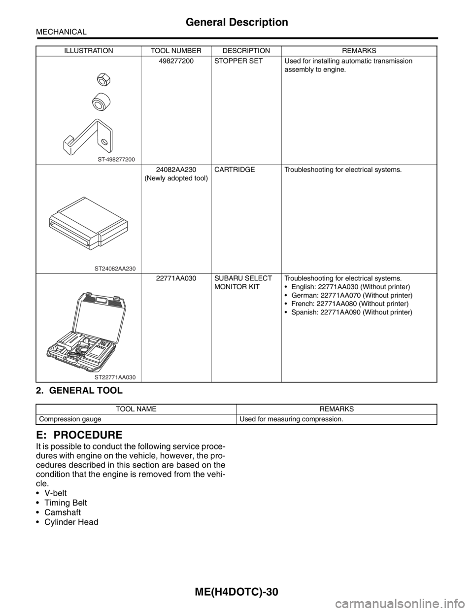
2. GENERAL TOOL
E: PROCEDURE
It is possible to conduct the following service proce-
dures with engine on the vehicle, however, the pro-
cedures described in this section are based on the
condition that the engine is removed from the vehi-
cle.
V-belt
Timing Belt
Camshaft
Cylinder Head
498277200 STOPPER SET Used for installing automatic transmission
assembly to engine.
24082AA230
(Newly adopted tool)CARTRIDGE Troubleshooting for electrical systems.
22771AA030 SUBARU SELECT
MONITOR KITTroubleshooting for electrical systems.
English: 22771AA030 (Without printer)
German: 22771AA070 (Without printer)
French: 22771AA080 (Without printer)
Spanish: 22771AA090 (Without printer)
TOOL NAME REMARKS
Compression gauge Used for measuring compression.ILLUSTRATION TOOL NUMBER DESCRIPTION REMARKS
ST-498277200
ST24082AA230
ST22771AA030
Page 1487 of 2870

ME(H4DOTC)-31
MECHANICAL
Compression
2. Compression
A: INSPECTION
CAUTION:
After warming-up, engine becomes very hot. Be
careful not to burn yourself during measure-
ment.
1) After warming-up the engine, turn the ignition
switch to OFF.
2) Make sure that the battery is fully charged.
3) Release the fuel pressure.
SURE, OPERATION, Fuel.>
4) Remove all the spark plugs.
5) Fully open the throttle valve.
6) Check the starter motor for satisfactory perfor-
mance and operation.
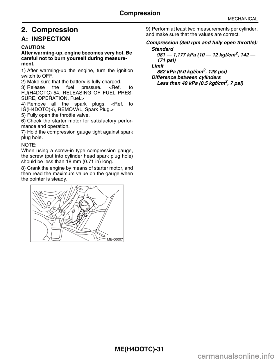
7) Hold the compression gauge tight against spark
plug hole.
NOTE:
When using a screw-in type compression gauge,
the screw (put into cylinder head spark plug hole)
should be less than 18 mm (0.71 in) long.
8) Crank the engine by means of starter motor, and
then read the maximum value on the gauge when
the pointer is steady.9) Perform at least two measurements per cylinder,
and make sure that the values are correct.
Compression (350 rpm and fully open throttle):
Standard
981 — 1,177 kPa (10 — 12 kgf/cm
2, 142 —
171 psi)
Limit
882 kPa (9.0 kgf/cm
2, 128 psi)
Difference between cylinders
Less than 49 kPa (0.5 kgf/cm
2, 7 psi)
ME-00007
Page 1498 of 2870

MECHANICAL
ME(H4DOTC)
Page
1. General Description ....................................................................................2
2. Compression .............................................................................................31
3. Idle Speed .................................................................................................32
4. Ignition Timing ...........................................................................................33
5. Intake Manifold Vacuum............................................................................34
6. Engine Oil Pressure ..................................................................................35
7. Fuel Pressure ............................................................................................36
8. Valve Clearance ........................................................................................37
9. Engine Assembly ......................................................................................41
10. Engine Mounting .......................................................................................50
11. Preparation for Overhaul ...........................................................................51
12. V-belt .........................................................................................................52
13. Crank Pulley ..............................................................................................55
14. Timing Belt Cover......................................................................................57
15. Timing Belt Assembly................................................................................58
16. Cam Sprocket ...........................................................................................67
17. Crank Sprocket .........................................................................................68
18. Camshaft ...................................................................................................69
19. Cylinder Head Assembly ...........................................................................76
20. Cylinder Block ...........................................................................................84
21. Intake and Exhaust Valve .......................................................................115
22. Piston ......................................................................................................116
23. Connecting Rod ......................................................................................117
24. Crankshaft ...............................................................................................118
25. Engine Trouble in General ......................................................................119
26. Engine Noise ...........................................................................................124