2004 SUBARU FORESTER garage
[x] Cancel search: garagePage 906 of 2870
ME(H4SO)-37
MECHANICAL
Engine Assembly
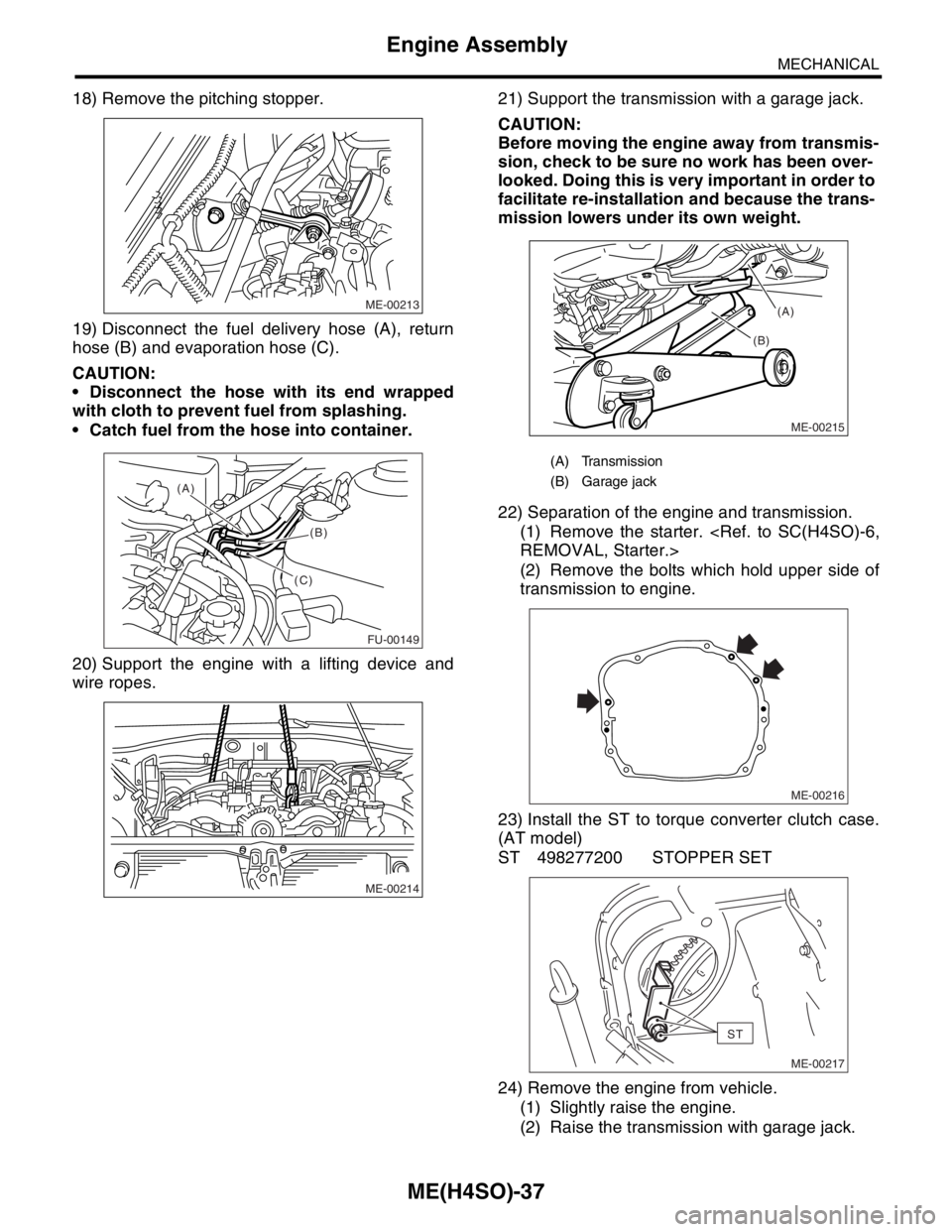
18) Remove the pitching stopper.
19) Disconnect the fuel delivery hose (A), return
hose (B) and evaporation hose (C).
CAUTION:
Disconnect the hose with its end wrapped
with cloth to prevent fuel from splashing.
Catch fuel from the hose into container.
20) Support the engine with a lifting device and
wire ropes.21) Support the transmission with a garage jack.
CAUTION:
Before moving the engine away from transmis-
sion, check to be sure no work has been over-
looked. Doing this is very important in order to
facilitate re-installation and because the trans-
mission lowers under its own weight.
22) Separation of the engine and transmission.
(1) Remove the starter.
(2) Remove the bolts which hold upper side of
transmission to engine.
23) Install the ST to torque converter clutch case.
(AT model)
ST 498277200 STOPPER SET
24) Remove the engine from vehicle.
(1) Slightly raise the engine.
(2) Raise the transmission with garage jack.
ME-00213
FU-00149
(A)
(B)
(C)
ME-00214
(A) Transmission
(B) Garage jack
ME-00215
(B)(A)
ME-00216
ST
ME-00217
Page 907 of 2870
ME(H4SO)-38
MECHANICAL
Engine Assembly
(3) Move the engine horizontally until main
shaft is withdrawn from clutch cover.
(4) Slowly move the engine away from engine
compartment.
NOTE:
Be careful not to damage the adjacent parts or
body panels with crank pulley, oil level gauge, etc.
25) Remove the front cushion rubbers.
B: INSTALLATION
1) Install the front cushion rubbers.
Tightening torque:
34 N
⋅m (3.5 kgf-m, 25.3 ft-lb)
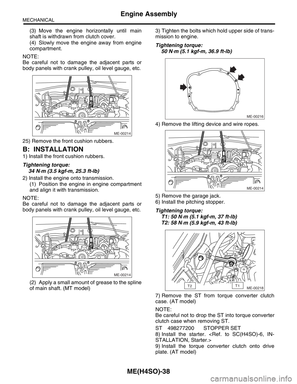
2) Install the engine onto transmission.
(1) Position the engine in engine compartment
and align it with transmission.
NOTE:
Be careful not to damage the adjacent parts or
body panels with crank pulley, oil level gauge, etc.
(2) Apply a small amount of grease to the spline
of main shaft. (MT model)3) Tighten the bolts which hold upper side of trans-
mission to engine.
Tightening torque:
50 N
⋅m (5.1 kgf-m, 36.9 ft-lb)
4) Remove the lifting device and wire ropes.
5) Remove the garage jack.
6) Install the pitching stopper.
Tightening torque:
T1: 50 N
⋅m (5.1 kgf-m, 37 ft-lb)
T2: 58 N
⋅m (5.9 kgf-m, 43 ft-lb)
7) Remove the ST from torque converter clutch
case. (AT model)
NOTE:
Be careful not to drop the ST into torque converter
clutch case when removing ST.
ST 498277200 STOPPER SET
8) Install the starter.
9) Install the torque converter clutch onto drive
plate. (AT model)
ME-00214
ME-00214
ME-00216
ME-00214
ME-00218T2T1
Page 1137 of 2870
EN(H4SO)-39
ENGINE (DIAGNOSTIC)
Inspection Mode
1. PREPARATION FOR THE INSPECTION
MODE
1) Check battery voltage is more than 12 V and fuel
remains half [20 — 402 (5.3 — 10.6 US gal, 4.4 —
8.8 Imp gal)].
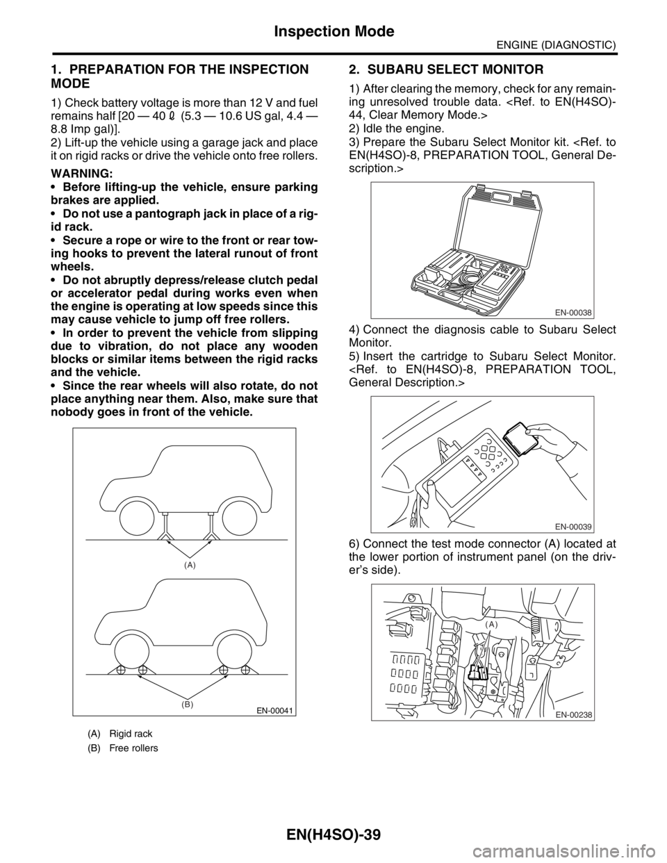
2) Lift-up the vehicle using a garage jack and place
it on rigid racks or drive the vehicle onto free rollers.
WARNING:
Before lifting-up the vehicle, ensure parking
brakes are applied.
Do not use a pantograph jack in place of a rig-
id rack.
Secure a rope or wire to the front or rear tow-
ing hooks to prevent the lateral runout of front
wheels.
Do not abruptly depress/release clutch pedal
or accelerator pedal during works even when
the engine is operating at low speeds since this
may cause vehicle to jump off free rollers.
In order to prevent the vehicle from slipping
due to vibration, do not place any wooden
blocks or similar items between the rigid racks
and the vehicle.
Since the rear wheels will also rotate, do not
place anything near them. Also, make sure that
nobody goes in front of the vehicle.
2. SUBARU SELECT MONITOR
1) After clearing the memory, check for any remain-
ing unresolved trouble data.
2) Idle the engine.
3) Prepare the Subaru Select Monitor kit.
scription.>
4) Connect the diagnosis cable to Subaru Select
Monitor.
5) Insert the cartridge to Subaru Select Monitor.
6) Connect the test mode connector (A) located at
the lower portion of instrument panel (on the driv-
er’s side).
(A) Rigid rack
(B) Free rollers
EN-00041
(A)
(B)
EN-00038
EN-00039
EN-00238
(A)
Page 1503 of 2870
ME(H4DOTC)-45
MECHANICAL
Engine Assembly
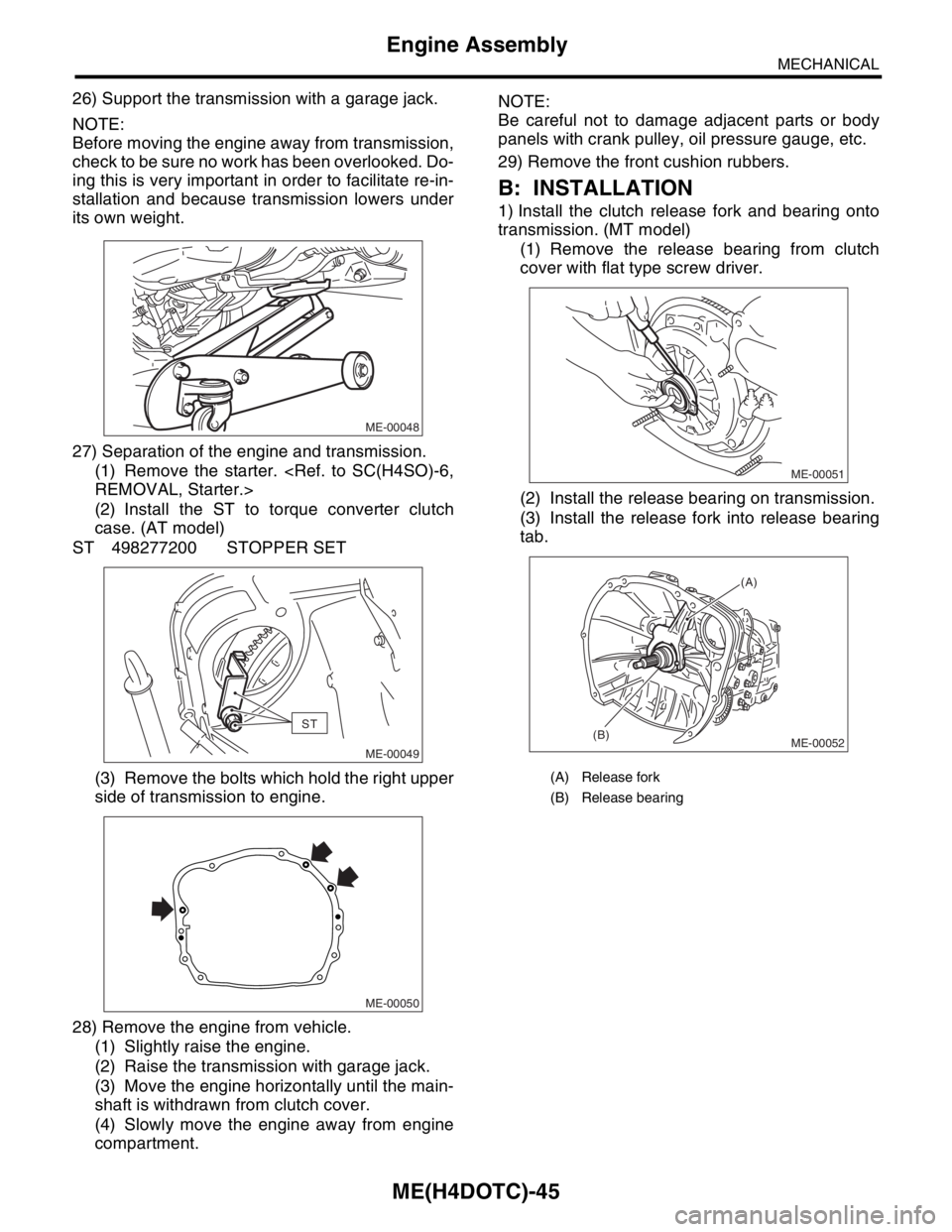
26) Support the transmission with a garage jack.
NOTE:
Before moving the engine away from transmission,
check to be sure no work has been overlooked. Do-
ing this is very important in order to facilitate re-in-
stallation and because transmission lowers under
its own weight.
27) Separation of the engine and transmission.
(1) Remove the starter.
(2) Install the ST to torque converter clutch
case. (AT model)
ST 498277200 STOPPER SET
(3) Remove the bolts which hold the right upper
side of transmission to engine.
28) Remove the engine from vehicle.
(1) Slightly raise the engine.
(2) Raise the transmission with garage jack.
(3) Move the engine horizontally until the main-
shaft is withdrawn from clutch cover.
(4) Slowly move the engine away from engine
compartment.NOTE:
Be careful not to damage adjacent parts or body
panels with crank pulley, oil pressure gauge, etc.
29) Remove the front cushion rubbers.
B: INSTALLATION
1) Install the clutch release fork and bearing onto
transmission. (MT model)
(1) Remove the release bearing from clutch
cover with flat type screw driver.
(2) Install the release bearing on transmission.
(3) Install the release fork into release bearing
tab.
ME-00048
ST
ME-00049
ME-00050
(A) Release fork
(B) Release bearing
ME-00051
ME-00052
(A)
(B)
Page 1505 of 2870
ME(H4DOTC)-47
MECHANICAL
Engine Assembly
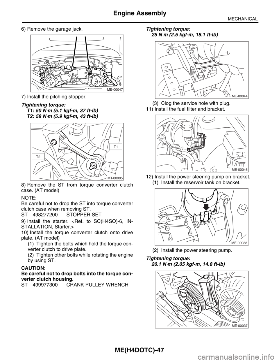
6) Remove the garage jack.
7) Install the pitching stopper.
Tightening torque:
T1: 50 N
⋅m (5.1 kgf-m, 37 ft-lb)
T2: 58 N
⋅m (5.9 kgf-m, 43 ft-lb)
8) Remove the ST from torque converter clutch
case. (AT model)
NOTE:
Be careful not to drop the ST into torque converter
clutch case when removing ST.
ST 498277200 STOPPER SET
9) Install the starter.
10) Install the torque converter clutch onto drive
plate. (AT model)
(1) Tighten the bolts which hold the torque con-
verter clutch to drive plate.
(2) Tighten other bolts while rotating the engine
by using ST.
CAUTION:
Be careful not to drop bolts into the torque con-
verter clutch housing.
ST 499977300 CRANK PULLEY WRENCHTightening torque:
25 N
⋅m (2.5 kgf-m, 18.1 ft-lb)
(3) Clog the service hole with plug.
11) Install the fuel filter and bracket.
12) Install the power steering pump on bracket.
(1) Install the reservoir tank on bracket.
(2) Install the power steering pump.
Tightening torque:
20.1 N
⋅m (2.05 kgf-m, 14.8 ft-lb)
ME-00047
T1
T2
MT-00085ME-00044
ME-00046
ME-00038
ME-00037
Page 1672 of 2870
EN(H4DOTC)-42
ENGINE (DIAGNOSTIC)
Inspection Mode
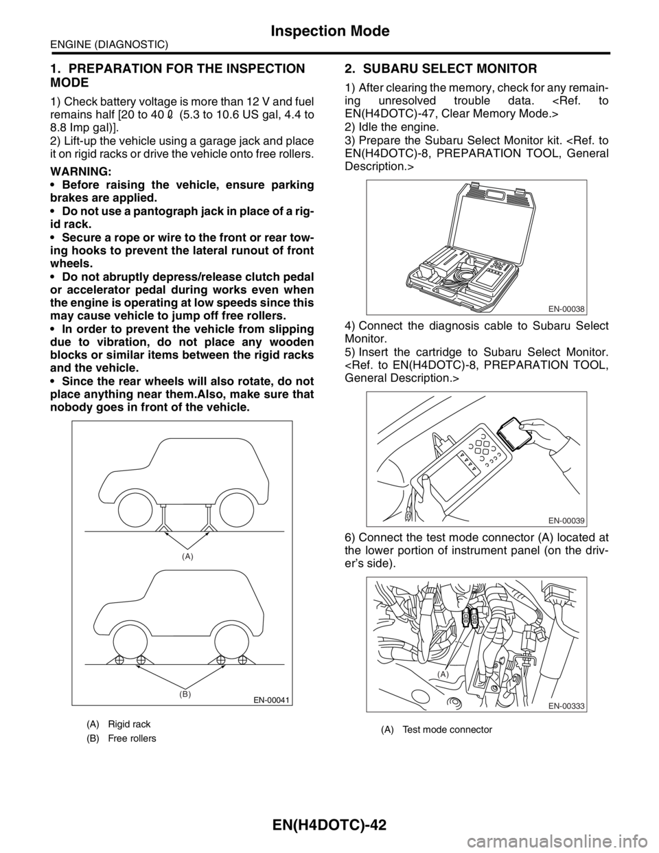
1. PREPARATION FOR THE INSPECTION
MODE
1) Check battery voltage is more than 12 V and fuel
remains half [20 to 402 (5.3 to 10.6 US gal, 4.4 to
8.8 Imp gal)].
2) Lift-up the vehicle using a garage jack and place
it on rigid racks or drive the vehicle onto free rollers.
WARNING:
Before raising the vehicle, ensure parking
brakes are applied.
Do not use a pantograph jack in place of a rig-
id rack.
Secure a rope or wire to the front or rear tow-
ing hooks to prevent the lateral runout of front
wheels.
Do not abruptly depress/release clutch pedal
or accelerator pedal during works even when
the engine is operating at low speeds since this
may cause vehicle to jump off free rollers.
In order to prevent the vehicle from slipping
due to vibration, do not place any wooden
blocks or similar items between the rigid racks
and the vehicle.
Since the rear wheels will also rotate, do not
place anything near them.Also, make sure that
nobody goes in front of the vehicle.
2. SUBARU SELECT MONITOR
1) After clearing the memory, check for any remain-
ing unresolved trouble data.
2) Idle the engine.
3) Prepare the Subaru Select Monitor kit.
Description.>
4) Connect the diagnosis cable to Subaru Select
Monitor.
5) Insert the cartridge to Subaru Select Monitor.
6) Connect the test mode connector (A) located at
the lower portion of instrument panel (on the driv-
er’s side).
(A) Rigid rack
(B) Free rollers
EN-00041
(A)
(B)
(A) Test mode connector
EN-00038
EN-00039
EN-00333
(A)
Page 2061 of 2870
EN(H4DOTC 2.5)-37
ENGINE (DIAGNOSTIC)
Inspection Mode
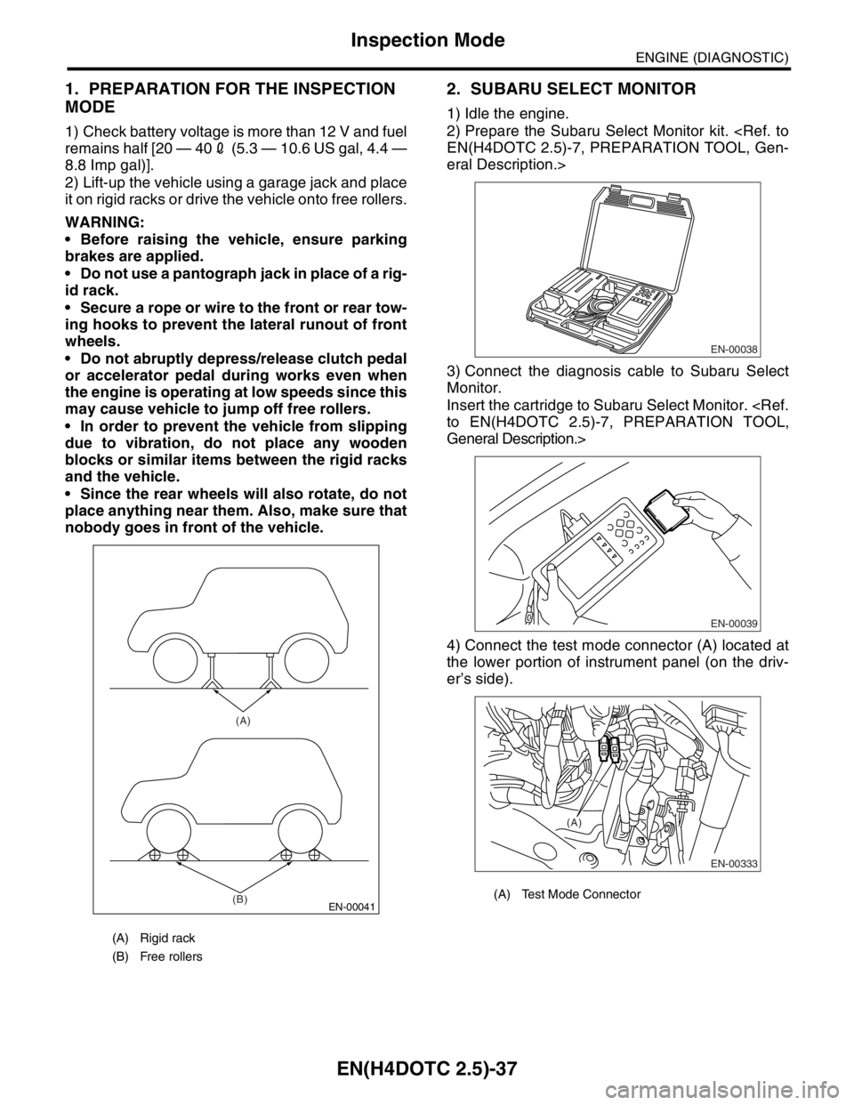
1. PREPARATION FOR THE INSPECTION
MODE
1) Check battery voltage is more than 12 V and fuel
remains half [20 — 402 (5.3 — 10.6 US gal, 4.4 —
8.8 Imp gal)].
2) Lift-up the vehicle using a garage jack and place
it on rigid racks or drive the vehicle onto free rollers.
WARNING:
Before raising the vehicle, ensure parking
brakes are applied.
Do not use a pantograph jack in place of a rig-
id rack.
Secure a rope or wire to the front or rear tow-
ing hooks to prevent the lateral runout of front
wheels.
Do not abruptly depress/release clutch pedal
or accelerator pedal during works even when
the engine is operating at low speeds since this
may cause vehicle to jump off free rollers.
In order to prevent the vehicle from slipping
due to vibration, do not place any wooden
blocks or similar items between the rigid racks
and the vehicle.
Since the rear wheels will also rotate, do not
place anything near them. Also, make sure that
nobody goes in front of the vehicle.
2. SUBARU SELECT MONITOR
1) Idle the engine.
2) Prepare the Subaru Select Monitor kit.
eral Description.>
3) Connect the diagnosis cable to Subaru Select
Monitor.
Insert the cartridge to Subaru Select Monitor.
General Description.>
4) Connect the test mode connector (A) located at
the lower portion of instrument panel (on the driv-
er’s side).
(A) Rigid rack
(B) Free rollers
EN-00041
(A)
(B)
(A) Test Mode Connector
EN-00038
EN-00039
EN-00333
(A)