2004 SUBARU FORESTER belt
[x] Cancel search: beltPage 1 of 2870

FUJI HEAVY INDUSTRIES LTD. G8080GE7
2004 FORESTER SERVICE MANUAL QUICK REFERENCE INDEX
BODY SECTION
This service manual has been prepared
to provide SUBARU service personnel
with the necessary information and data
for the correct maintenance and repair
of SUBARU vehicles.
This manual includes the procedures
for maintenance, disassembling, reas-
sembling, inspection and adjustment of
components and diagnostics for guid-
ance of experienced mechanics.
Please peruse and utilize this manual
fully to ensure complete repair work for
satisfying our customers by keeping
their vehicle in optimum condition.
When replacement of parts during
repair work is needed, be sure to use
SUBARU genuine parts.
All information, illustration and specifi-
cations contained in this manual are
based on the latest product information
available at the time of publication
approval.HVAC SYSTEM
(HEATER, VENTILATOR AND A/C)AC
HVAC SYSTEM (AUTO A/C)
(DIAGNOSTIC)AC
AIRBAG SYSTEM AB
AIRBAG SYSTEM (DIAGNOSTIC) AB
SEAT BELT SYSTEM SB
LIGHTING SYSTEM LI
WIPER AND WASHER SYSTEM WW
ENTERTAINMENT ET
COMMUNICATION SYSTEM COM
GLASS/WINDOW/MIRROR GW
BODY STRUCTURE BS
INSTRUMENTATION/DRIVER INFO IDI
SEAT SE
SECURITY AND LOCK SL
SUNROOF/T-TOP/CONVERTIBLE TOP
(SUNROOF)SR
EXTERIOR/INTERIOR TRIM EI
EXTERIOR BODY PANEL EB
Page 4 of 2870

AC-2
HVAC SYSTEM (HEATER, VENTILATOR AND A/C)
General Description
1. General Description
A: SPECIFICATION
1. HEATER SYSTEM
2. A/C SYSTEM
AUTO A/C MODEL
Item Specifications Condition
Heating capacity5.0 kW (4,300 kcal/h,
17,062 BTU/h) or more• Mode selector switch: HEAT
• Temperature control switch: FULL HOT
• Temperature difference between hot water
and inlet air: 65°C (149°F)
• Hot water flow rate: 3602 (95.1 US gal, 79.2
Imp gal)/h
Air flow rate
280 m
3 (9,888 cu ft)/hHeat mode (FRESH), FULL HOT at 12.5 V
Max air flow rate
480 m
3 (16,951 cu ft)/h• Temperature control switch: FULL COLD
• Blower fan speed: 4th position
• Mode selector lever: RECIRC
Heater core size
(height×length×width)134.1×224.3×32 mm
(5.28×8.83×1.26 in)—
Blower motorTy p eAuto A/C (Brushless motor)
230 W or less12.5 V
Manual A/C (Cylinder motor)
260 W or less12.5 V
Fan type and size
(diameter×width)Sirocco fan type
150×75 mm (5.91×2.95 in)—
Item Specifications
Type of air conditioner Reheat air-mix type
Cooling capacity5.1 kW
(4,386 kcal/h, 17,403 BTU/h)
RefrigerantHFC-134a (CH
2FCF3)
[0.6±0.05 kg (1.32±0.11 lb)]
CompressorType Vane rotary, fix volume (DKV-14G)
Discharge
140 cm
3 (8.54 cu in)/rev
Max. permissible speed 7,000 rpm
Magnet clutchType Dry, single-disc type
Power consumption 38 W (DC 12 V-25°C)
Type of belt V-belt 4 PK
Pulley dia. (effective dia.) 125 mm (4.92 in)
Pulley ratio 1.064
CondenserType Corrugated fin (Sub cool type)
Core face area
0.234 m
2 (2.52 sq ft)
Core thickness 16 mm (0.63 in)
Radiation area
5.6 m
2 (62.28 sq ft)
Receiver drier Effective inner capacity
220 cm
3 (13.42 cu in)
Expansion valve Type External equalizing
EvaporatorType Single tank
Dimensions (W×H×T)176.5×266×60 mm
(6.95×10.47×2.36 in)
Blower fanFan type Sirocco fan
Outer diameter×width 150×75 mm (5.91×2.95 in)
Power consumption 230 W or less at 12.5 V
Page 5 of 2870
AC-3
HVAC SYSTEM (HEATER, VENTILATOR AND A/C)
General Description
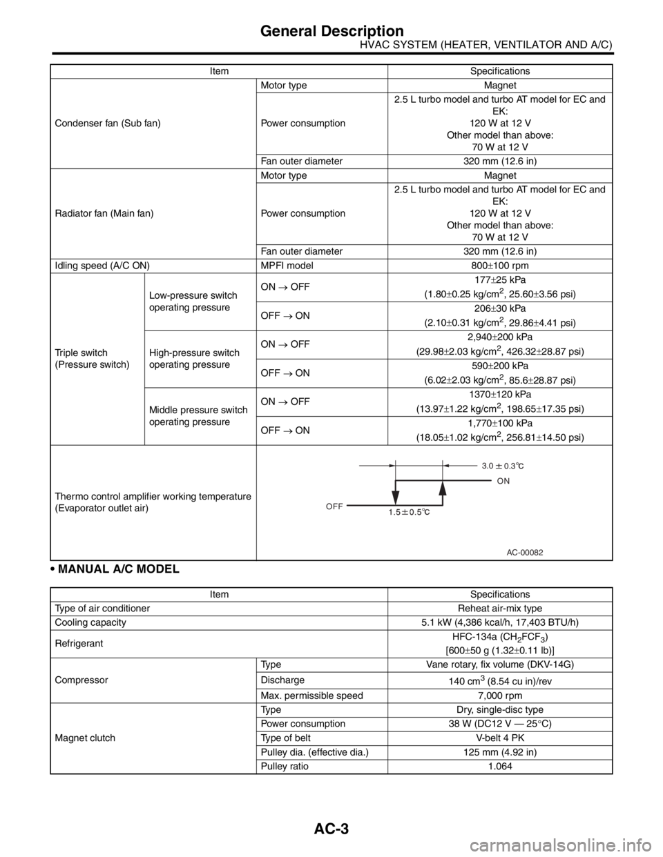
MANUAL A/C MODEL
Condenser fan (Sub fan)Motor type Magnet
Power consumption2.5 L turbo model and turbo AT model for EC and
EK:
120 W at 12 V
Other model than above:
70 W at 12 V
Fan outer diameter 320 mm (12.6 in)
Radiator fan (Main fan)Motor type Magnet
Power consumption2.5 L turbo model and turbo AT model for EC and
EK:
120 W at 12 V
Other model than above:
70 W at 12 V
Fan outer diameter 320 mm (12.6 in)
Idling speed (A/C ON) MPFI model 800±100 rpm
Triple switch
(Pressure switch)Low-pressure switch
operating pressureON → OFF177±25 kPa
(1.80±0.25 kg/cm
2, 25.60±3.56 psi)
OFF → ON206±30 kPa
(2.10±0.31 kg/cm
2, 29.86±4.41 psi)
High-pressure switch
operating pressureON → OFF2,940±200 kPa
(29.98±2.03 kg/cm
2, 426.32±28.87 psi)
OFF → ON590±200 kPa
(6.02±2.03 kg/cm
2, 85.6±28.87 psi)
Middle pressure switch
operating pressureON → OFF1370±120 kPa
(13.97±1.22 kg/cm
2, 198.65±17.35 psi)
OFF → ON1,770±100 kPa
(18.05±1.02 kg/cm
2, 256.81±14.50 psi)
Thermo control amplifier working temperature
(Evaporator outlet air)
Item Specifications
Type of air conditioner Reheat air-mix type
Cooling capacity 5.1 kW (4,386 kcal/h, 17,403 BTU/h)
RefrigerantHFC-134a (CH
2FCF3)
[600±50 g (1.32±0.11 lb)]
CompressorType Vane rotary, fix volume (DKV-14G)
Discharge
140 cm
3 (8.54 cu in)/rev
Max. permissible speed 7,000 rpm
Magnet clutchType Dry, single-disc type
Power consumption 38 W (DC12 V — 25°C)
Type of belt V-belt 4 PK
Pulley dia. (effective dia.) 125 mm (4.92 in)
Pulley ratio 1.064 Item Specifications
AC-00082
OFFON
3.0
0.3
Page 20 of 2870
AC-18
HVAC SYSTEM (HEATER, VENTILATOR AND A/C)
General Description
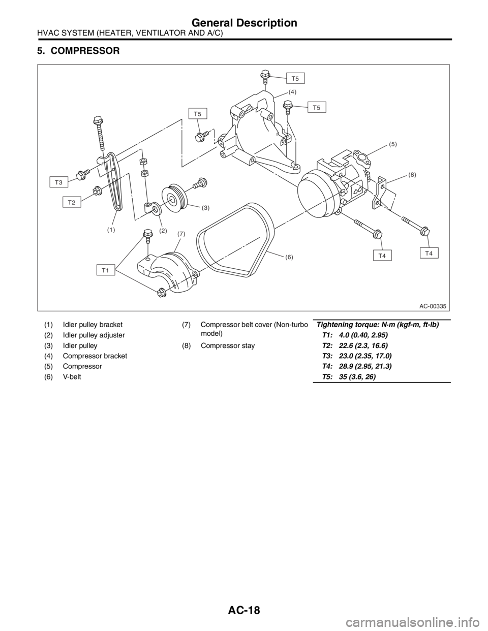
5. COMPRESSOR
(1) Idler pulley bracket (7) Compressor belt cover (Non-turbo
model)Tightening torque: N·m (kgf-m, ft-lb)
(2) Idler pulley adjusterT1: 4.0 (0.40, 2.95)
(3) Idler pulley (8) Compressor stayT2: 22.6 (2.3, 16.6)
(4) Compressor bracketT3: 23.0 (2.35, 17.0)
(5) CompressorT4: 28.9 (2.95, 21.3)
(6) V-beltT5: 35 (3.6, 26)
AC-00335
(1)
(3)
(2)
(4)
(5)
(8)
(6)
(7)
T3
T2
T1
T5
T5
T5
T4T4
Page 38 of 2870
AC-36
HVAC SYSTEM (HEATER, VENTILATOR AND A/C)
Compressor
11.Compressor
A: INSPECTION
1. MAGNETIC CLUTCH CLEARANCE
1) Check the clearance of the entire circumference
around the drive plate and pulley.
Standard:
0.3 — 0.6 mm (0.0118 — 0.0236 in)
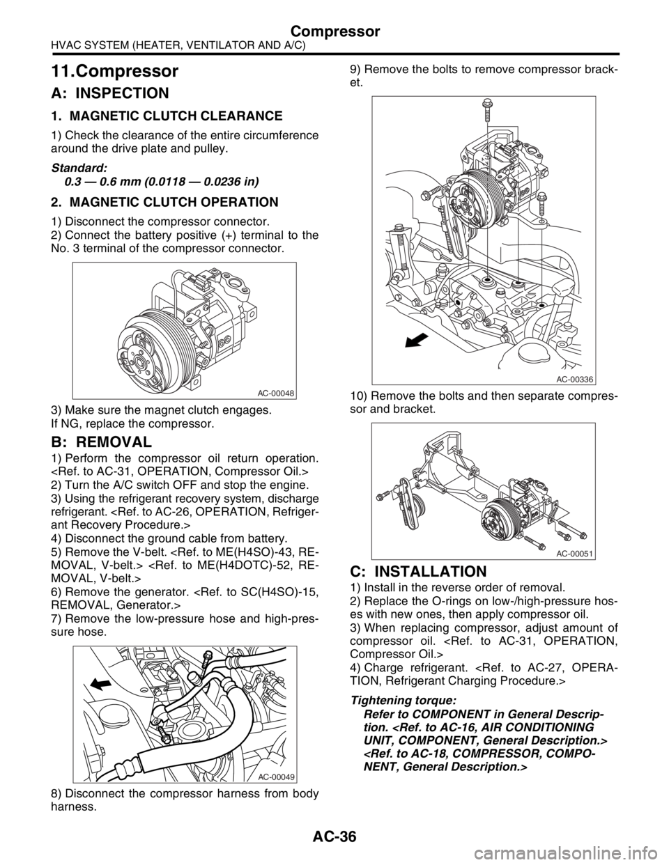
2. MAGNETIC CLUTCH OPERATION
1) Disconnect the compressor connector.
2) Connect the battery positive (+) terminal to the
No. 3 terminal of the compressor connector.
3) Make sure the magnet clutch engages.
If NG, replace the compressor.
B: REMOVAL
1) Perform the compressor oil return operation.
2) Turn the A/C switch OFF and stop the engine.
3) Using the refrigerant recovery system, discharge
refrigerant.
4) Disconnect the ground cable from battery.
5) Remove the V-belt.
6) Remove the generator.
7) Remove the low-pressure hose and high-pres-
sure hose.
8) Disconnect the compressor harness from body
harness.9) Remove the bolts to remove compressor brack-
et.
10) Remove the bolts and then separate compres-
sor and bracket.
C: INSTALLATION
1) Install in the reverse order of removal.
2) Replace the O-rings on low-/high-pressure hos-
es with new ones, then apply compressor oil.
3) When replacing compressor, adjust amount of
compressor oil.
4) Charge refrigerant.
Tightening torque:
Refer to COMPONENT in General Descrip-
tion.
AC-00048
AC-00049
AC-00336
AC-00051
Page 55 of 2870
FUJI HEAVY INDUSTRIES LTD. G8080GE7
2004 FORESTER SERVICE MANUAL QUICK REFERENCE INDEX
BODY SECTION
This service manual has been prepared
to provide SUBARU service personnel
with the necessary information and data
for the correct maintenance and repair
of SUBARU vehicles.
This manual includes the procedures
for maintenance, disassembling, reas-
sembling, inspection and adjustment of
components and diagnostics for guid-
ance of experienced mechanics.
Please peruse and utilize this manual
fully to ensure complete repair work for
satisfying our customers by keeping
their vehicle in optimum condition.
When replacement of parts during
repair work is needed, be sure to use
SUBARU genuine parts.
All information, illustration and specifi-
cations contained in this manual are
based on the latest product information
available at the time of publication
approval.HVAC SYSTEM
(HEATER, VENTILATOR AND A/C)AC
HVAC SYSTEM (AUTO A/C)
(DIAGNOSTIC)AC
AIRBAG SYSTEM AB
AIRBAG SYSTEM (DIAGNOSTIC) AB
SEAT BELT SYSTEM SB
LIGHTING SYSTEM LI
WIPER AND WASHER SYSTEM WW
ENTERTAINMENT ET
COMMUNICATION SYSTEM COM
GLASS/WINDOW/MIRROR GW
BODY STRUCTURE BS
INSTRUMENTATION/DRIVER INFO IDI
SEAT SE
SECURITY AND LOCK SL
SUNROOF/T-TOP/CONVERTIBLE TOP
(SUNROOF)SR
EXTERIOR/INTERIOR TRIM EI
EXTERIOR BODY PANEL EB
Page 99 of 2870
FUJI HEAVY INDUSTRIES LTD. G8080GE7
2004 FORESTER SERVICE MANUAL QUICK REFERENCE INDEX
BODY SECTION
This service manual has been prepared
to provide SUBARU service personnel
with the necessary information and data
for the correct maintenance and repair
of SUBARU vehicles.
This manual includes the procedures
for maintenance, disassembling, reas-
sembling, inspection and adjustment of
components and diagnostics for guid-
ance of experienced mechanics.
Please peruse and utilize this manual
fully to ensure complete repair work for
satisfying our customers by keeping
their vehicle in optimum condition.
When replacement of parts during
repair work is needed, be sure to use
SUBARU genuine parts.
All information, illustration and specifi-
cations contained in this manual are
based on the latest product information
available at the time of publication
approval.HVAC SYSTEM
(HEATER, VENTILATOR AND A/C)AC
HVAC SYSTEM (AUTO A/C)
(DIAGNOSTIC)AC
AIRBAG SYSTEM AB
AIRBAG SYSTEM (DIAGNOSTIC) AB
SEAT BELT SYSTEM SB
LIGHTING SYSTEM LI
WIPER AND WASHER SYSTEM WW
ENTERTAINMENT ET
COMMUNICATION SYSTEM COM
GLASS/WINDOW/MIRROR GW
BODY STRUCTURE BS
INSTRUMENTATION/DRIVER INFO IDI
SEAT SE
SECURITY AND LOCK SL
SUNROOF/T-TOP/CONVERTIBLE TOP
(SUNROOF)SR
EXTERIOR/INTERIOR TRIM EI
EXTERIOR BODY PANEL EB
Page 107 of 2870
AB-7
AIRBAG SYSTEM
General Description
C: PREPARATION TOOL
1. SPECIAL TOOL
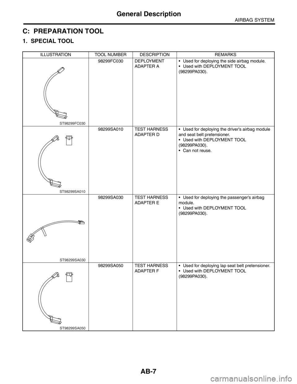
ILLUSTRATION TOOL NUMBER DESCRIPTION REMARKS
98299FC030 DEPLOYMENT
ADAPTER A Used for deploying the side airbag module.
Used with DEPLOYMENT TOOL
(98299PA030).
98299SA010 TEST HARNESS
ADAPTER D Used for deploying the driver’s airbag module
and seat belt pretensioner.
Used with DEPLOYMENT TOOL
(98299PA030).
Can not reuse.
98299SA030 TEST HARNESS
ADAPTER E Used for deploying the passenger’s airbag
module.
Used with DEPLOYMENT TOOL
(98299PA030).
98299SA050 TEST HARNESS
ADAPTER F Used for deploying lap seat belt pretensioner.
Used with DEPLOYMENT TOOL
(98299PA030).
ST98299FC030
ST98299SA010
ST98299SA030
ST98299SA050