Page 1714 of 2870

EN(H4DOTC)-81
ENGINE (DIAGNOSTIC)
Diagnostic Procedure with Diagnostic Trouble Code (DTC)
B: DTC P0021 “A” CAMSHAFT POSITION - TIMING OVER - ADVANCED OR
SYSTEM PERFORMANCE (BANK 2)
DTC DETECTING CONDITION:
Detect as soon as the malfunction occurs.
TROUBLE SYMPTOM:
Engine stalls.
Erroneous idling
CAUTION:
After repair or replacement of faulty parts, conduct Clear Memory Mode
ERATION, Clear Memory Mode.> and Inspection Mode .
Step Check Yes No
1 CHECK DTC ON DISPLAY.Is any other DTC displayed? Inspect the rele-
vant DTC using
“List of Diagnostic
Trouble Code
(DTC)”.
EN(H4DOTC)-74,
List of Diagnostic
Trouble Code
(DTC).>Go to step 2.
2 CHECK CURRENT DATA.
1) Start the engine and idle it.
2) Check the AVCS system operating angle
and oil flow control solenoid valve duty output
using Subaru Select Monitor or OBD-II general
scan tool.
NOTE:
Subaru Select Monitor
For detailed operation procedure, refer to
“READ CURRENT DATA SHOWN ON DIS-
PLAY FOR ENGINE”.
33, Subaru Select Monitor.>
OBD-II general scan tool
For detailed operation procedures, refer to the
OBD-II General Scan Tool Operation Manual.Is the AVCS system operating
angle approx. 0 degree and oil
flow control solenoid valve duty
output approx. 10%?A temporary poor
malfunction. Per-
for m the following
to clean oil routing.
Replace the
engine oil, and
then idle the
engine for 5 min-
utes and replace
the oil filter and
engine oil.Check the follow-
ing and repair or
replace it if neces-
sary.
Engine oil
(amount, dirt)
Oil pipe (clog-
ging)
Oil flow con-
trol solenoid
valve (clogging
or dirt of oil
routing, spring
setting, clog-
ging of valve)
Intake cam-
shaft (dirt, dam-
age of
camshaft)
Timing belt
(alignment of
timing mark)
Page 1800 of 2870

EN(H4DOTC)-167
ENGINE (DIAGNOSTIC)
Diagnostic Procedure with Diagnostic Trouble Code (DTC)
6 CHECK POWER SUPPLY LINE.
1) Turn the ignition switch to ON.
2) Measure the voltage between fuel injector
and engine ground on faulty cylinders.
Connector & terminal
#1 (E5) No. 2 (+) — Engine ground (
−):
#2 (E16) No. 2 (+) — Engine ground (
−):
#3 (E6) No. 2 (+) — Engine ground (
−):
#4 (E17) No. 2 (+) — Engine ground (
−):Is the voltage more than 10 V? Repair poor con-
tact in all connec-
tors in fuel injector
circuit.Repair the har-
ness and connec-
tor.
N
OTE:
In this case repair
the following:
Open circuit in
harness between
main relay and fuel
injector connector
on faulty cylinders
Poor contact in
coupling connector
Poor contact in
main relay connec-
tor
Poor contact in
fuel injector con-
nector on faulty
cylinders
7 CHECK HARNESS BETWEEN FUEL INJEC-
TOR AND ECM CONNECTOR.
1) Turn the ignition switch to OFF.
2) Disconnect the connector from fuel injector
on faulty cylinder.
3) Turn the ignition switch to ON.
4) Measure the voltage between ECM con-
nector and chassis ground on faulty cylinders.
Connector & terminal
#1 (B136) No. 6 (+) — Chassis ground (
−):
#2 (B136 No. 5 (+) — Chassis ground (
−):
#3 (B136 No. 4 (+) — Chassis ground (
−):
#4 (B136 No. 3 (+) — Chassis ground (
−):Is the voltage more than 10 V? Repair battery
short circuit in har-
ness between
ECM and fuel
injector.After
repair, replace the
ECM.
FU(H4DOTC)-50,
Engine Control
Module (ECM).>Go to step 8.
8 CHECK FUEL INJECTOR.
1) Turn the ignition switch to OFF.
2) Measure the resistance between fuel injec-
tor terminals on faulty cylinder.
Te r m i n a l s
No. 1 — No. 2:Is the resistance less than 1
Ω?Replace the faulty
fuel injector and
ECM.
FU(H4DOTC)-38,
Fuel Injector.>
FU(H4DOTC)-50,
Engine Control
Module (ECM).>Go to step 9.
9 CHECK INSTALLATION OF CAMSHAFT PO-
SITION SENSOR/CRANKSHAFT POSITION
SENSOR.Is the installation of camshaft
position sensor or crankshaft
position sensor loosened?Tighten camshaft
position sensor or
crankshaft posi-
tion sensor.Go to step 10.
10 CHECK CRANK SPROCKET.
Remove the timing belt cover.Is the crank sprocket rusted or
does it have broken teeth?Replace the crank
sprocket.
ME(H4DOTC)-67,
Crank Sprocket.>Go to step 11.
11 CHECK INSTALLATION CONDITION OF
TIMING BELT.
Turn the crankshaft, and align alignment mark
on crank sprocket with alignment mark on cyl-
inder block.Is the timing belt dislocated
from its proper position?Repair installation
condition of timing
belt.
ME(H4DOTC)-58,
Timing Belt
Assembly.>Go to step 12. Step Check Yes No
Page 1809 of 2870

EN(H4DOTC)-176
ENGINE (DIAGNOSTIC)
Diagnostic Procedure with Diagnostic Trouble Code (DTC)
Step Check Yes No
1 CHECK ANY OTHER DTC ON DISPLAY.Is any other DTC displayed? Inspect the rele-
vant DTC using
“List of Diagnostic
Trouble Code
(DTC)”.
EN(H4DOTC)-74,
List of Diagnostic
Trouble Code
(DTC).>Go to step 2.
2 CHECK CONDITION OF CRANKSHAFT PO-
SITION SENSOR.
Turn the ignition switch to OFF.Is the crankshaft position sen-
sor installation bolt tightened
securely?Go to step 3.Tighten the crank-
shaft position sen-
sor installation bolt
securely.
3 CHECK CRANK SPROCKET.
Remove the front belt cover.Are crank sprocket teeth
cracked or damaged?Replace the crank
sprocket.
ME(H4DOTC)-67,
Crank Sprocket.>Go to step 4.
4 CHECK INSTALLATION CONDITION OF
TIMING BELT.
Turn the crankshaft, and align alignment mark
on crank sprocket with alignment mark on cyl-
inder block.Is the timing belt dislocated
from its proper position?Repair installation
condition of timing
belt.
ME(H4DOTC)-58,
Timing Belt
Assembly.>Replace the crank-
shaft position sen-
sor.
FU(H4DOTC)-30,
Crankshaft Posi-
tion Sensor.>
Page 1814 of 2870

EN(H4DOTC)-181
ENGINE (DIAGNOSTIC)
Diagnostic Procedure with Diagnostic Trouble Code (DTC)
5 CHECK CONDITION OF CAMSHAFT POSI-
TION SENSOR CONNECTOR.Is the camshaft position sensor
connector installation bolt tight-
ened securely?Go to step 6.Tighten the cam-
shaft position sen-
sor connector
installation bolt
securely.
6 CHECK CAMSHAFT POSITION SENSOR
CONNECTOR.
1) Remove the camshaft position sensor con-
nector.
2) Measure the resistance between connector
terminals of camshaft position sensor connec-
tor.
Te r m i n a l s
No. 1 — No. 2:Is the resistance 1 — 4 kΩ? Go to step 7.Replace the cam-
shaft position sen-
sor connector.
FU(H4DOTC)-31,
Camshaft Position
Sensor.>
7 CHECK CONDITION OF CAMSHAFT POSI-
TION SENSOR CONNECTOR.
Turn the ignition switch to OFF.Is the camshaft position sensor
connector installation bolt tight-
ened securely?Go to step 8.Tighten the cam-
shaft position sen-
sor connector
installation bolt
securely.
8 CHECK CAM SPROCKET.
Remove the front belt cover.
ME(H4DOTC)-57, Timing Belt Cover.>Are cam sprocket teeth
cracked or damaged?Replace the cam
sprocket.
ME(H4DOTC)-66,
Cam Sprocket.>Go to step 9.
9 CHECK INSTALLATION CONDITION OF
TIMING BELT.
Turn the crankshaft, and align alignment mark
on camshaft sprocket with alignment mark on
timing belt cover LH.Is the timing belt dislocated
from its proper position?Repair installation
condition of timing
belt.
ME(H4DOTC)-58,
Timing Belt
Assembly.>Replace the cam-
shaft position sen-
sor connector.
FU(H4DOTC)-31,
Camshaft Position
Sensor.> Step Check Yes No
Page 1944 of 2870

FU(H4DOTC 2.5)-14
FUEL INJECTION (FUEL SYSTEM)
Intake Manifold
3. Intake Manifold
A: REMOVAL
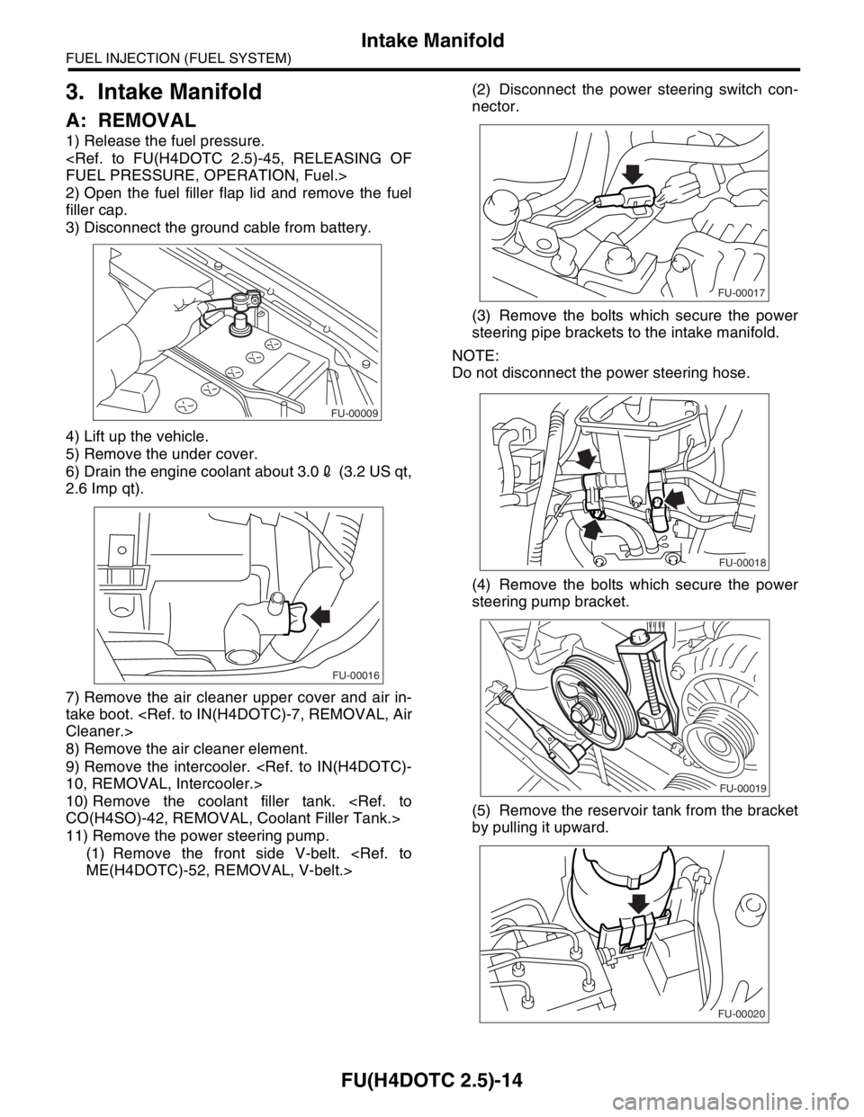
1) Release the fuel pressure.
FUEL PRESSURE, OPERATION, Fuel.>
2) Open the fuel filler flap lid and remove the fuel
filler cap.
3) Disconnect the ground cable from battery.
4) Lift up the vehicle.
5) Remove the under cover.
6) Drain the engine coolant about 3.02 (3.2 US qt,
2.6 Imp qt).
7) Remove the air cleaner upper cover and air in-
take boot.
Cleaner.>
8) Remove the air cleaner element.
9) Remove the intercooler.
10, REMOVAL, Intercooler.>
10) Remove the coolant filler tank.
CO(H4SO)-42, REMOVAL, Coolant Filler Tank.>
11) Remove the power steering pump.
(1) Remove the front side V-belt.
ME(H4DOTC)-52, REMOVAL, V-belt.>(2) Disconnect the power steering switch con-
nector.
(3) Remove the bolts which secure the power
steering pipe brackets to the intake manifold.
NOTE:
Do not disconnect the power steering hose.
(4) Remove the bolts which secure the power
steering pump bracket.
(5) Remove the reservoir tank from the bracket
by pulling it upward.
FU-00009
FU-00016
FU-00017
FU-00018
FU-00019
FU-00020
Page 1949 of 2870

FU(H4DOTC 2.5)-19
FUEL INJECTION (FUEL SYSTEM)
Intake Manifold
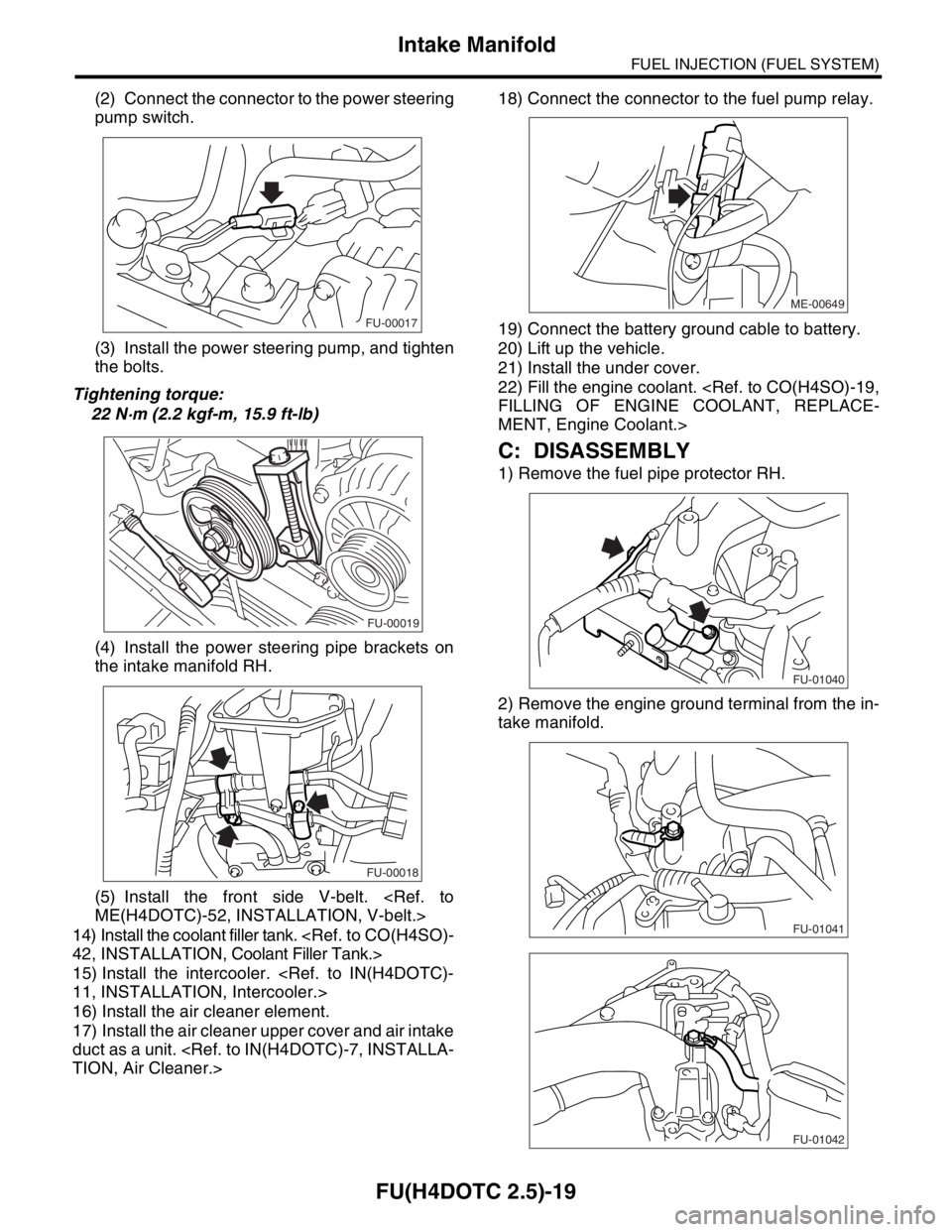
(2) Connect the connector to the power steering
pump switch.
(3) Install the power steering pump, and tighten
the bolts.
Tightening torque:
22 N·m (2.2 kgf-m, 15.9 ft-lb)
(4) Install the power steering pipe brackets on
the intake manifold RH.
(5) Install the front side V-belt.
ME(H4DOTC)-52, INSTALLATION, V-belt.>
14) Install the coolant filler tank.
42, INSTALLATION, Coolant Filler Tank.>
15) Install the intercooler.
11, INSTALLATION, Intercooler.>
16) Install the air cleaner element.
17) Install the air cleaner upper cover and air intake
duct as a unit.
TION, Air Cleaner.>18) Connect the connector to the fuel pump relay.
19) Connect the battery ground cable to battery.
20) Lift up the vehicle.
21) Install the under cover.
22) Fill the engine coolant.
FILLING OF ENGINE COOLANT, REPLACE-
MENT, Engine Coolant.>
C: DISASSEMBLY
1) Remove the fuel pipe protector RH.
2) Remove the engine ground terminal from the in-
take manifold.
FU-00017
FU-00019
FU-00018
ME-00649
FU-01040
FU-01041
FU-01042