2004 SUBARU FORESTER belt
[x] Cancel search: beltPage 1526 of 2870
ME(H4DOTC)-68
MECHANICAL
Camshaft
18.Camshaft
A: REMOVAL
1) Remove the V-belt.
2) Remove the crank pulley.
3) Remove the timing belt cover.
4) Remove the timing belt assembly.
bly.>
5) Remove the cam sprocket.
6) Remove the crank sprocket.
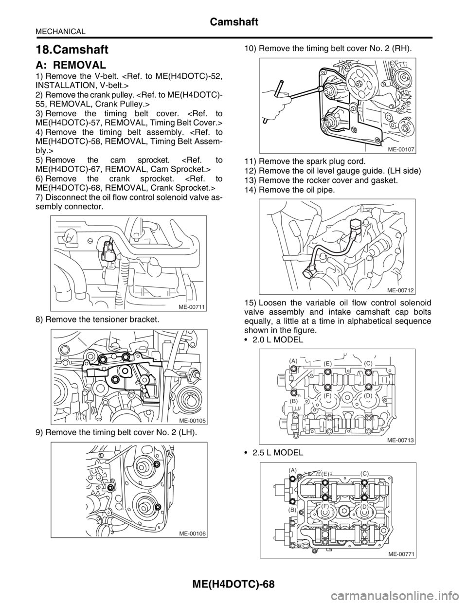
7) Disconnect the oil flow control solenoid valve as-
sembly connector.
8) Remove the tensioner bracket.
9) Remove the timing belt cover No. 2 (LH).10) Remove the timing belt cover No. 2 (RH).
11) Remove the spark plug cord.
12) Remove the oil level gauge guide. (LH side)
13) Remove the rocker cover and gasket.
14) Remove the oil pipe.
15) Loosen the variable oil flow control solenoid
valve assembly and intake camshaft cap bolts
equally, a little at a time in alphabetical sequence
shown in the figure.
2.0 L MODEL
2.5 L MODEL
ME-00711
ME-00105
ME-00106
ME-00107
ME-00712
ME-00713
(B)
(A)
(E)
(F) (D)(C)
ME-00771
(A)(E)
(F)(B)(D)
(C)
Page 1527 of 2870
ME(H4DOTC)-69
MECHANICAL
Camshaft
16) Remove the oil flow control solenoid valve as-
sembly, intake camshaft cap, and camshaft.
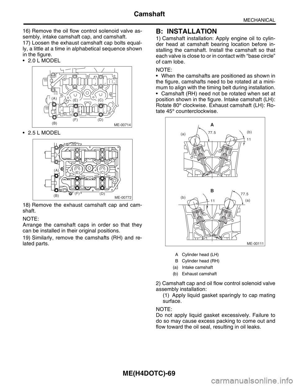
17) Loosen the exhaust camshaft cap bolts equal-
ly, a little at a time in alphabetical sequence shown
in the figure.
2.0 L MODEL
2.5 L MODEL
18) Remove the exhaust camshaft cap and cam-
shaft.
NOTE:
Arrange the camshaft caps in order so that they
can be installed in their original positions.
19) Similarly, remove the camshafts (RH) and re-
lated parts.B: INSTALLATION
1) Camshaft installation: Apply engine oil to cylin-
der head at camshaft bearing location before in-
stalling the camshaft. Install the camshaft so that
each valve is close to or in contact with “base circle”
of cam lobe.
NOTE:
When the camshafts are positioned as shown in
the figure, camshafts need to be rotated at a mini-
mum to align with the timing belt during installation.
Camshaft (RH) need not be rotated when set at
position shown in the figure. Intake camshaft (LH):
Rotate 80° clockwise. Exhaust camshaft (LH): Ro-
tate 45° counterclockwise.
2) Camshaft cap and oil flow control solenoid valve
assembly installation:
(1) Apply liquid gasket sparingly to cap mating
surface.
NOTE:
Do not apply liquid gasket excessively. Failure to
do so may cause excess packing to come out and
flow toward the oil seal, resulting in oil leaks.
ME-00714(B)
(A)
(E)
(F) (D)(C)
ME-00772
(A)(E)
(F)(B)(D)
(C)
A Cylinder head (LH)
B Cylinder head (RH)
(a) Intake camshaft
(b) Exhaust camshaft
ME-00111
1111
77.5 77.5
(a)
(b)
(a)(b)
A
B
Page 1530 of 2870
ME(H4DOTC)-72
MECHANICAL
Camshaft
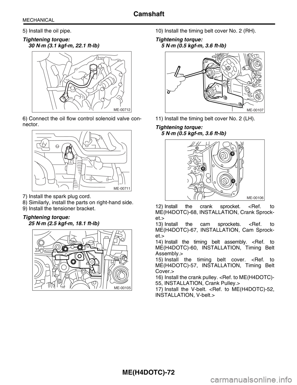
5) Install the oil pipe.
Tightening torque:
30 N
⋅m (3.1 kgf-m, 22.1 ft-lb)
6) Connect the oil flow control solenoid valve con-
nector.
7) Install the spark plug cord.
8) Similarly, install the parts on right-hand side.
9) Install the tensioner bracket.
Tightening torque:
25 N
⋅m (2.5 kgf-m, 18.1 ft-lb)10) Install the timing belt cover No. 2 (RH).
Tightening torque:
5 N
⋅m (0.5 kgf-m, 3.6 ft-lb)
11) Install the timing belt cover No. 2 (LH).
Tightening torque:
5 N
⋅m (0.5 kgf-m, 3.6 ft-lb)
12) Install the crank sprocket.
et.>
13) Install the cam sprockets.
et.>
14) Install the timing belt assembly.
Assembly.>
15) Install the timing belt cover.
Cover.>
16) Install the crank pulley.
17) Install the V-belt.
ME-00712
ME-00711
ME-00105
ME-00107
ME-00106
Page 1533 of 2870
ME(H4DOTC)-75
MECHANICAL
Cylinder Head Assembly
19.Cylinder Head Assembly
A: REMOVAL
1) Remove the V-belt.
2) Remove the crank pulley.
3) Remove the timing belt cover.
4) Remove the timing belt assembly.
bly.>
5) Remove the cam sprocket.
6) Remove the intake manifold.
7) Remove the bolt which installs the A/C compres-
sor bracket on cylinder head.
8) Remove the camshaft.
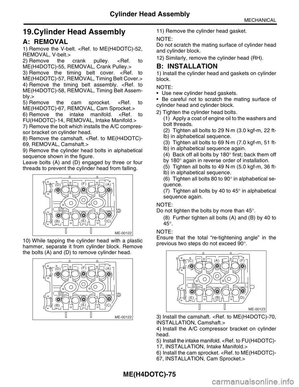
9) Remove the cylinder head bolts in alphabetical
sequence shown in the figure.
Leave bolts (A) and (D) engaged by three or four
threads to prevent the cylinder head from falling.
10) While tapping the cylinder head with a plastic
hammer, separate it from cylinder block. Remove
the bolts (A) and (D) to remove cylinder head.11) Remove the cylinder head gasket.
NOTE:
Do not scratch the mating surface of cylinder head
and cylinder block.
12) Similarly, remove the cylinder head (RH).
B: INSTALLATION
1) Install the cylinder head and gaskets on cylinder
block.
NOTE:
Use new cylinder head gaskets.
Be careful not to scratch the mating surface of
cylinder head and cylinder block.
2) Tighten the cylinder head bolts.
(1) Apply a coat of engine oil to the washers and
bolt threads.
(2) Tighten all bolts to 29 N⋅m (3.0 kgf-m, 22 ft-
lb) in alphabetical sequence.
(3) Tighten all bolts to 69 N⋅m (7.0 kgf-m, 51 ft-
lb) in alphabetical sequence again.
(4) Back off all bolts by 180° first; back them off
by 180° again in reverse order of installation.
(5) Tighten all bolts to 49 N⋅m (5.0 kgf-m, 36 ft-
lb) in alphabetical sequence.
(6) Tighten all bolts 80 to 90° in alphabetical se-
quence.
(7) Tighten all bolts by 40 to 45° in alphabetical
sequence again.
NOTE:
Do not tighten the bolts by more than 45°.
(8) Further tighten all bolts (A) and (B) by 40 to
45°.
NOTE:
Ensure that the total “re-tightening angle” in the
previous two steps do not exceed 90°.
3) Install the camshaft.
4) Install the A/C compressor bracket on cylinder
head.
5) Install the intake manifold.
6) Install the cam sprocket.
ME-00122
(B)(C)
(D)
(E)
(F)(A)
ME-00122
(B)(C)
(D)
(E)
(F)(A)
ME-00123
(B)
(C)
(D)(E)
(F)(A)
Page 1534 of 2870
ME(H4DOTC)-76
MECHANICAL
Cylinder Head Assembly
7) Install the timing belt assembly.
Assembly.>
8) Install the timing belt cover.
Cover.>
9) Install the crank pulley.
10) Install the V-belt.
C: DISASSEMBLY
1) Remove the valve lifters.
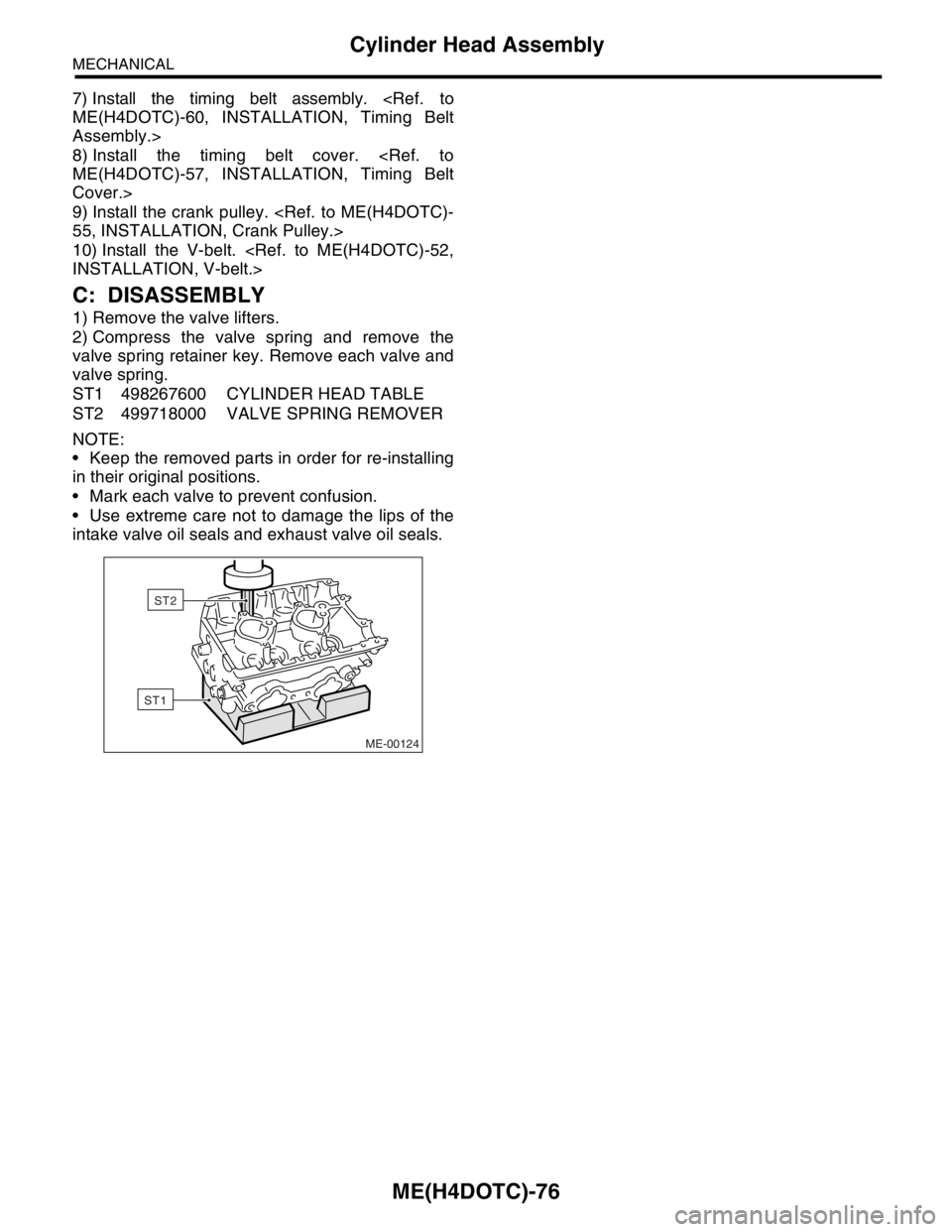
2) Compress the valve spring and remove the
valve spring retainer key. Remove each valve and
valve spring.
ST1 498267600 CYLINDER HEAD TABLE
ST2 499718000 VALVE SPRING REMOVER
NOTE:
Keep the removed parts in order for re-installing
in their original positions.
Mark each valve to prevent confusion.
Use extreme care not to damage the lips of the
intake valve oil seals and exhaust valve oil seals.
ME-00124
ST1
ST2
Page 1542 of 2870

MECHANICAL
ME(H4DOTC)
Page
1. General Description ....................................................................................2
2. Compression .............................................................................................31
3. Idle Speed .................................................................................................32
4. Ignition Timing ...........................................................................................33
5. Intake Manifold Vacuum............................................................................34
6. Engine Oil Pressure ..................................................................................35
7. Fuel Pressure ............................................................................................36
8. Valve Clearance ........................................................................................37
9. Engine Assembly ......................................................................................41
10. Engine Mounting .......................................................................................50
11. Preparation for Overhaul ...........................................................................51
12. V-belt .........................................................................................................52
13. Crank Pulley ..............................................................................................55
14. Timing Belt Cover......................................................................................57
15. Timing Belt Assembly................................................................................58
16. Cam Sprocket ...........................................................................................67
17. Crank Sprocket .........................................................................................68
18. Camshaft ...................................................................................................69
19. Cylinder Head Assembly ...........................................................................76
20. Cylinder Block ...........................................................................................84
21. Intake and Exhaust Valve .......................................................................115
22. Piston ......................................................................................................116
23. Connecting Rod ......................................................................................117
24. Crankshaft ...............................................................................................118
25. Engine Trouble in General ......................................................................119
26. Engine Noise ...........................................................................................124
Page 1543 of 2870
ME(H4DOTC)-83
MECHANICAL
Cylinder Block
20.Cylinder Block
A: REMOVAL
NOTE:
Before conducting this procedure, drain the engine
oil completely if applicable.
1) Remove the intake manifold.
2) Remove the V-belt.
3) Remove the crank pulley.
4) Remove the timing belt cover.
5) Remove the timing belt assembly.
bly.>
6) Remove the cam sprocket.
7) Remove the crank sprocket.
8) Remove the generator and A/C compressor with
their brackets.
9) Remove the cylinder head assembly.
sembly.>
10) Remove the clutch disc and cover. (MT model)
11) Remove the flywheel. (MT model)
12) Remove the drive plate. (AT model)
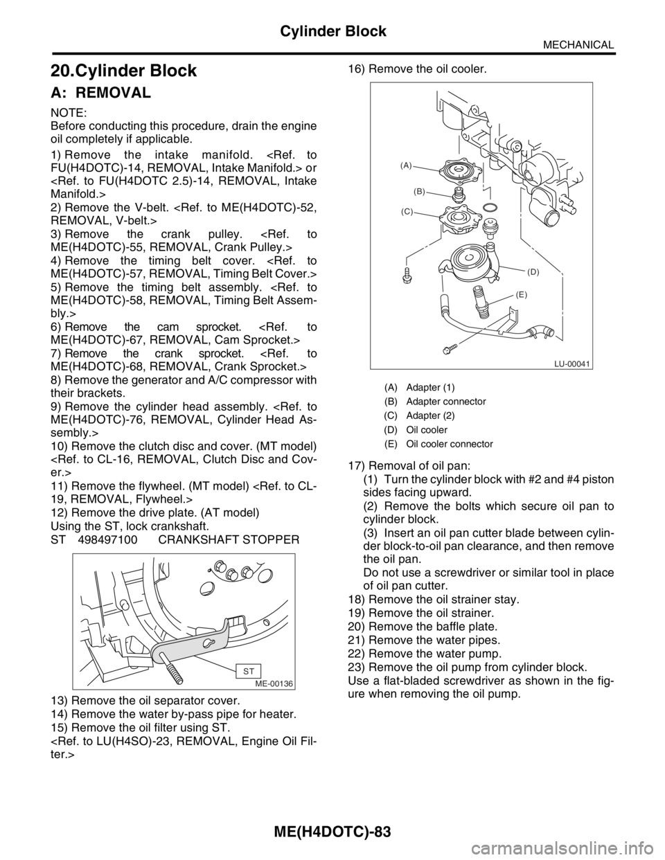
Using the ST, lock crankshaft.
ST 498497100 CRANKSHAFT STOPPER
13) Remove the oil separator cover.
14) Remove the water by-pass pipe for heater.
15) Remove the oil filter using ST.
17) Removal of oil pan:
(1) Turn the cylinder block with #2 and #4 piston
sides facing upward.
(2) Remove the bolts which secure oil pan to
cylinder block.
(3) Insert an oil pan cutter blade between cylin-
der block-to-oil pan clearance, and then remove
the oil pan.
Do not use a screwdriver or similar tool in place
of oil pan cutter.
18) Remove the oil strainer stay.
19) Remove the oil strainer.
20) Remove the baffle plate.
21) Remove the water pipes.
22) Remove the water pump.
23) Remove the oil pump from cylinder block.
Use a flat-bladed screwdriver as shown in the fig-
ure when removing the oil pump.
ME-00136
ST
(A) Adapter (1)
(B) Adapter connector
(C) Adapter (2)
(D) Oil cooler
(E) Oil cooler connector
LU-00041
(A)
(B)
(C)
(D)
(E)
Page 1555 of 2870
ME(H4DOTC)-95
MECHANICAL
Cylinder Block
33) Install the oil filter using ST.
34) Install the water by-pass pipe between oil cool-
er and water pump.
35) Install the water pipe.
NOTE:
Always use a new O-ring.
36) Install the cylinder head assembly.
Assembly.>
37) Install the oil level gauge guide and tighten the
attaching bolt (LH side).
38) Install the rocker cover.
39) Install the crank sprocket.
et.>40) Install the cam sprocket.
et.>
41) Install the timing belt assembly.
Assembly.>
42) Install the timing belt cover.
Cover.>
43) Install the crank pulley.
44) Install the generator and A/C compressor
brackets on cylinder head.
45) Install the V-belt.
46) Install the intake manifold.
fold.>
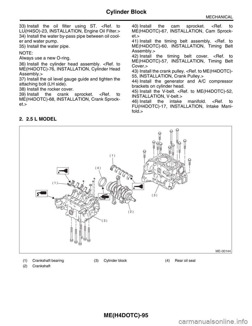
2. 2.5 L MODEL
(1) Crankshaft bearing (3) Cylinder block (4) Rear oil seal
(2) Crankshaft
ME-00144
( 1 )
( 1 )
( 2 )
( 3 )
( 3 )
( 4 )