Page 1510 of 2870
ME(H4DOTC)-52
MECHANICAL
V-belt
12.V-belt
A: REMOVAL
1. FRONT SIDE BELT
1) Remove the V-belt cover.
2) Loosen the lock bolt (A).
3) Loosen the slider bolt (B).
4) Remove the front side belt (C).
2. REAR SIDE BELT
1) Loosen the lock nut (A).
2) Loosen the slider bolt (B).
3) Remove the A/C belt.4) Remove the A/C belt tensioner.
B: INSTALLATION
1. FRONT SIDE BELT
CAUTION:
Wipe off any oil or water on the belt and pulley.
1) Install the belt (C), and tighten the slider bolt so
as to obtain the specified belt tension
ME(H4DOTC)-53, INSPECTION, V-belt.>
2) Tighten the lock bolt (A).
3) Tighten the slider bolt (B).
Tightening torque:
Lock bolt through bolt:
25 N
⋅m (2.5 kgf-m, 18.1 ft-lb)
Slider bolt:
8 N
⋅m (0.8 kgf-m, 5.5 ft-lb)
SC-00096
(A)
(C) (B)
ME-00059
(A)
(B)
ME-00060
ME-00061
(A)
(C) (B)
ME-00059
Page 1511 of 2870
ME(H4DOTC)-53
MECHANICAL
V-belt
2. REAR SIDE BELT
1) Install the belt, and tighten the slider bolt (B) so
as to obtain the specified belt tension.
ME(H4DOTC)-53, INSPECTION, V-belt.>
2) Tighten the lock nut (A).
Tightening torque:
Lock nut (A);
22.6 N
⋅m (2.3 kgf-m, 16.6 ft-lb)
C: INSPECTION
1) Replace the belts, if cracks, fraying or wear is
found.
2) Check the drive belt tension and adjust it if nec-
essary by changing generator installing position
and/or idler pulley installing position.
Belt tension (With using belt tension gauge)
(A)
Replaced: 640 — 780 N (65 — 80 kgf, 144 —
175 lb)
Reused: 490 — 640 N (50 — 65 kgf, 110 — 144
lb)
(B)*
Replaced: 740 — 880 N (76 — 89 kgf, 167 —
197 lb)
Reused: 350 — 450 N (36 — 46 kgf, 78 — 101
lb)
*: With air conditioner
(A)
(B)
ME-00060
(A) Front side belt
(B) Rear side belt
C/P Crank pulley
GEN Generator
P/S Power steering oil pump pulley
A/C A/C compressor pulley
I/P Idler pulley
C/P P/SA/C
GEN
(A)
(B)
I/P
PM-00154
Page 1512 of 2870
ME(H4DOTC)-54
MECHANICAL
V-belt
Belt tension (Without using belt tension gauge)
(A)
Replaced: 7 — 9 mm (0.276 — 0.354 in)
Reused: 9 — 11 mm (0.354 — 0.433 in)
(B)*
Replaced: 7.5 — 8.5 mm (0.295 — 0.335 in)
Reused: 9.0 — 10.0 mm (0.354 — 0.394 in)
*: With air conditioner
(A) Front side belt
(B) Rear side belt
C/P Crank pulley
GEN Generator
P/S Power steering oil pump pulley
A/C Air conditioning compressor pulley
I/P Idler pulley
ME-00062
P/S
C/PGEN
I/P A/C 98 N (10 kgf, 22 lb)
(A)(B)
Page 1513 of 2870

ME(H4DOTC)-55
MECHANICAL
Crank Pulley
13.Crank Pulley
A: REMOVAL
1) Remove the V-belt.
REMOVAL, V-belt.>
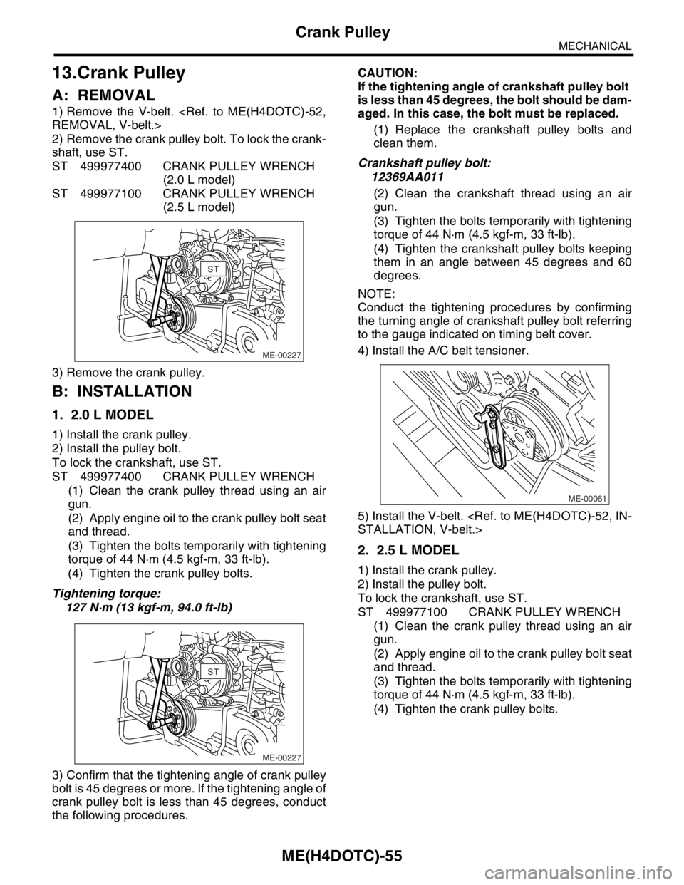
2) Remove the crank pulley bolt. To lock the crank-
shaft, use ST.
ST 499977400 CRANK PULLEY WRENCH
(2.0 L model)
ST 499977100 CRANK PULLEY WRENCH
(2.5 L model)
3) Remove the crank pulley.
B: INSTALLATION
1. 2.0 L MODEL
1) Install the crank pulley.
2) Install the pulley bolt.
To lock the crankshaft, use ST.
ST 499977400 CRANK PULLEY WRENCH
(1) Clean the crank pulley thread using an air
gun.
(2) Apply engine oil to the crank pulley bolt seat
and thread.
(3) Tighten the bolts temporarily with tightening
torque of 44 N⋅m (4.5 kgf-m, 33 ft-lb).
(4) Tighten the crank pulley bolts.
Tightening torque:
127 N
⋅m (13 kgf-m, 94.0 ft-lb)
3) Confirm that the tightening angle of crank pulley
bolt is 45 degrees or more. If the tightening angle of
crank pulley bolt is less than 45 degrees, conduct
the following procedures.CAUTION:
If the tightening angle of crankshaft pulley bolt
is less than 45 degrees, the bolt should be dam-
aged. In this case, the bolt must be replaced.
(1) Replace the crankshaft pulley bolts and
clean them.
Crankshaft pulley bolt:
12369AA011
(2) Clean the crankshaft thread using an air
gun.
(3) Tighten the bolts temporarily with tightening
torque of 44 N⋅m (4.5 kgf-m, 33 ft-lb).
(4) Tighten the crankshaft pulley bolts keeping
them in an angle between 45 degrees and 60
degrees.
NOTE:
Conduct the tightening procedures by confirming
the turning angle of crankshaft pulley bolt referring
to the gauge indicated on timing belt cover.
4) Install the A/C belt tensioner.
5) Install the V-belt.
STALLATION, V-belt.>
2. 2.5 L MODEL
1) Install the crank pulley.
2) Install the pulley bolt.
To lock the crankshaft, use ST.
ST 499977100 CRANK PULLEY WRENCH
(1) Clean the crank pulley thread using an air
gun.
(2) Apply engine oil to the crank pulley bolt seat
and thread.
(3) Tighten the bolts temporarily with tightening
torque of 44 N⋅m (4.5 kgf-m, 33 ft-lb).
(4) Tighten the crank pulley bolts.
ME-00227
STST
ME-00227
STST
ME-00061
Page 1514 of 2870

ME(H4DOTC)-56
MECHANICAL
Crank Pulley
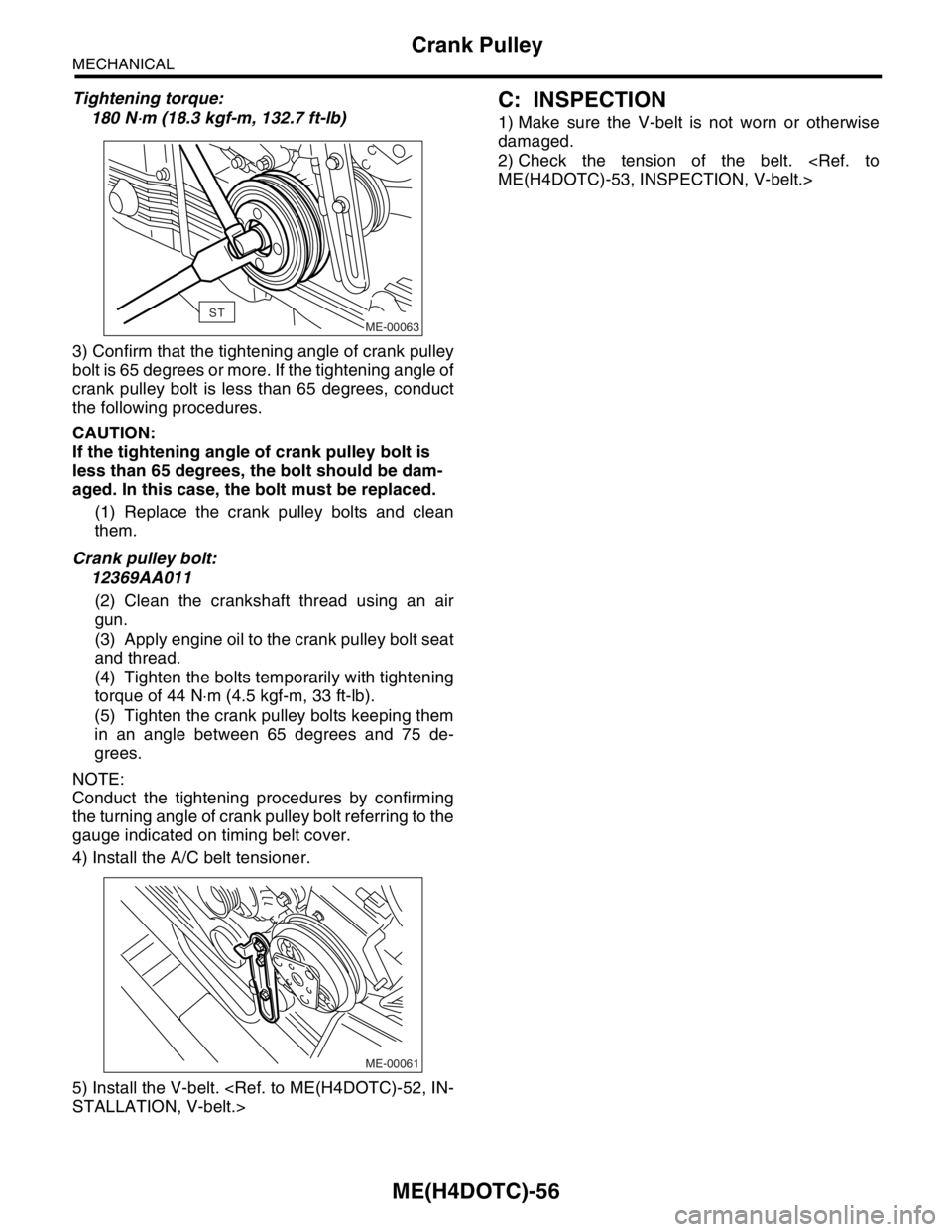
Tightening torque:
180 N
⋅m (18.3 kgf-m, 132.7 ft-lb)
3) Confirm that the tightening angle of crank pulley
bolt is 65 degrees or more. If the tightening angle of
crank pulley bolt is less than 65 degrees, conduct
the following procedures.
CAUTION:
If the tightening angle of crank pulley bolt is
less than 65 degrees, the bolt should be dam-
aged. In this case, the bolt must be replaced.
(1) Replace the crank pulley bolts and clean
them.
Crank pulley bolt:
12369AA011
(2) Clean the crankshaft thread using an air
gun.
(3) Apply engine oil to the crank pulley bolt seat
and thread.
(4) Tighten the bolts temporarily with tightening
torque of 44 N⋅m (4.5 kgf-m, 33 ft-lb).
(5) Tighten the crank pulley bolts keeping them
in an angle between 65 degrees and 75 de-
grees.
NOTE:
Conduct the tightening procedures by confirming
the turning angle of crank pulley bolt referring to the
gauge indicated on timing belt cover.
4) Install the A/C belt tensioner.
5) Install the V-belt.
STALLATION, V-belt.>
C: INSPECTION
1) Make sure the V-belt is not worn or otherwise
damaged.
2) Check the tension of the belt.
ME(H4DOTC)-53, INSPECTION, V-belt.>
ME-00063ST
ME-00061
Page 1515 of 2870
ME(H4DOTC)-57
MECHANICAL
Timing Belt Cover
14.Timing Belt Cover
A: REMOVAL
1) Remove the V-belt.
REMOVAL, V-belt.>
2) Remove the crank pulley.
55, REMOVAL, Crank Pulley.>
3) Remove the timing belt cover (LH) (A).
4) Remove the timing belt cover (RH) (B).
5) Remove the front timing belt cover (C).
B: INSTALLATION
1) Install the front timing belt cover (C).
Tightening torque:
5 N
⋅m (0.5 kgf-m, 3.6 ft-lb)
2) Install the timing belt cover (RH) (B).
Tightening torque:
5 N
⋅m (0.5 kgf-m, 3.6 ft-lb)
3) Install the timing belt cover (LH) (A).
Tightening torque:
5 N
⋅m (0.5 kgf-m, 3.6 ft-lb)
4) Install the crank pulley.
55, INSTALLATION, Crank Pulley.>
5) Install the V-belt.
STALLATION, V-belt.>
C: INSPECTION
Make sure the cover is not damaged.
ME-00064
(A)
(C) (B)
ME-00064
(A)
(C) (B)
Page 1516 of 2870
ME(H4DOTC)-58
MECHANICAL
Timing Belt Assembly
15.Timing Belt Assembly
A: REMOVAL
1. TIMING BELT
1) Remove the V-belt.
REMOVAL, V-belt.>
2) Remove the crank pulley.
ME(H4DOTC)-55, REMOVAL, Crank Pulley.>
3) Remove the timing belt cover.
ME(H4DOTC)-57, REMOVAL, Timing Belt Cover.>
4) Remove the timing belt guides. (MT model)5) If the alignment mark and/or arrow mark (which
indicates rotation direction) on timing belt fade
away, put new marks before removing the timing
belt as follows:
(1) Turn the crankshaft using ST, and align the
alignment marks on crankshaft sprocket, intake
camshaft sprocket (LH), exhaust camshaft
sprocket (LH), intake camshaft sprocket (RH)
and exhaust camshaft sprocket (RH) with notch-
es of timing belt cover and cylinder block.
ST 499987500 CRANKSHAFT SOCKET
(2) Using white paint, put alignment and/or ar-
row marks on the timing belts in relation to the
sprockets.
ME-00065
ME-00727
ME-00728
ME-00729
ME-00069ST
ME-00070
ME-00071
Page 1517 of 2870

ME(H4DOTC)-59
MECHANICAL
Timing Belt Assembly
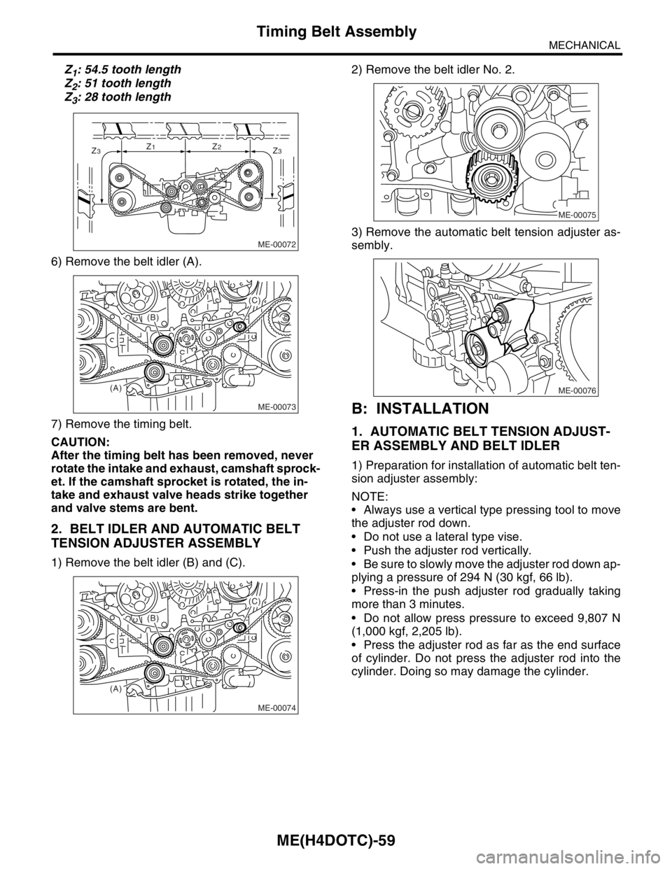
Z1: 54.5 tooth length
Z
2: 51 tooth length
Z
3: 28 tooth length
6) Remove the belt idler (A).
7) Remove the timing belt.
CAUTION:
After the timing belt has been removed, never
rotate the intake and exhaust, camshaft sprock-
et. If the camshaft sprocket is rotated, the in-
take and exhaust valve heads strike together
and valve stems are bent.
2. BELT IDLER AND AUTOMATIC BELT
TENSION ADJUSTER ASSEMBLY
1) Remove the belt idler (B) and (C).2) Remove the belt idler No. 2.
3) Remove the automatic belt tension adjuster as-
sembly.
B: INSTALLATION
1. AUTOMATIC BELT TENSION ADJUST-
ER ASSEMBLY AND BELT IDLER
1) Preparation for installation of automatic belt ten-
sion adjuster assembly:
NOTE:
Always use a vertical type pressing tool to move
the adjuster rod down.
Do not use a lateral type vise.
Push the adjuster rod vertically.
Be sure to slowly move the adjuster rod down ap-
plying a pressure of 294 N (30 kgf, 66 lb).
Press-in the push adjuster rod gradually taking
more than 3 minutes.
Do not allow press pressure to exceed 9,807 N
(1,000 kgf, 2,205 lb).
Press the adjuster rod as far as the end surface
of cylinder. Do not press the adjuster rod into the
cylinder. Doing so may damage the cylinder.
ME-00072
Z3Z1Z2Z3
ME-00073
(A)(B)
(C)
ME-00074
(A)(B)
(C)
ME-00075
ME-00076