2004 SUBARU FORESTER belt
[x] Cancel search: beltPage 1245 of 2870

EN(H4SO)-147
ENGINE (DIAGNOSTIC)
Diagnostic Procedure with Diagnostic Trouble Code (DTC)
23 GROUP OF #3 AND #4 CYLINDERS.Are there faults in #3 and #4
cylinders?Repair or replace
the faulty par t.
N
OTE:
Check the fol-
lowing items:
Spark plug
Fuel injector
Ignition coil
If no abnormal is
discovered, check
for “16. D: IGNI-
TION CONTROL
SYSTEM” of #3
and #4 cylinders
side.
IGNITION CON-
TROL SYSTEM,
Diagnostics for
Engine Starting
Fa il u r e. >Go to DTC P0171.
DTC P0171 SYS-
TEM TOO LEAN
(BANK 1), Diag-
nostic Procedure
with Diagnostic
Trouble Code
(DTC).>
24 GROUP OF #1 AND #3 CYLINDERS.Are there faults in #1 and #3
cylinders?Repair or replace
the faulty par t.
N
OTE:
Check the follow-
ing items:
Spark plug
Fuel injector
Skipping timing
belt teethGo to DTC P0171.
DTC P0171 SYS-
TEM TOO LEAN
(BANK 1), Diag-
nostic Procedure
with Diagnostic
Trouble Code
(DTC).>
25 GROUP OF #2 AND #4 CYLINDERS.Are there faults in #2 and #4
cylinders?Repair or replace
the faulty par t.
NOTE:
Check the follow-
ing items:
Spark plug
Fuel injector
Compression
ratio
Skipping timing
belt teethGo to DTC P0171.
DTC P0171 SYS-
TEM TOO LEAN
(BANK 1), Diag-
nostic Procedure
with Diagnostic
Trouble Code
(DTC).>
26 CYLINDER AT RANDOM.Is the engine idle rough? Go to DTC P0171.
DTC P0171 SYS-
TEM TOO LEAN
(BANK 1), Diag-
nostic Procedure
with Diagnostic
Trouble Code
(DTC).>Repair or replace
the faulty part.
N
OTE:
Check the follow-
ing items:
Spark plug
Fuel injector
Compression
ratio Step Check Yes No
Page 1253 of 2870

EN(H4SO)-155
ENGINE (DIAGNOSTIC)
Diagnostic Procedure with Diagnostic Trouble Code (DTC)
Step Check Yes No
1 CHECK ANY OTHER DTC ON DISPLAY.Is any other DTC displayed? Inspect the DTC
using “List of Diag-
nostic Trouble
Code (DTC)”.
of Diagnostic Trou-
ble Code (DTC).>Go to step 2.
2 CHECK CONDITION OF CRANKSHAFT PO-
SITION SENSOR.
Turn the ignition switch to OFF.Is the crankshaft position sen-
sor installation bolt tightened
securely?Go to step 3.Tighten the crank-
shaft position sen-
sor installation bolt
securely.
3 CHECK CRANK SPROCKET.
Remove the front belt cover.Are crank sprocket teeth
cracked or damaged?Replace the crank
sprocket.
Crank Sprocket.>Go to step 4.
4 CHECK INSTALLATION CONDITION OF
TIMING BELT.
Turn the crankshaft using ST, and align align-
ment mark on crank sprocket with alignment
mark on cylinder block.
ST 499987500 CRANKSHAFT SOCKETIs the timing belt dislocated
from its proper position?Repair installation
condition of timing
belt.
Timing Belt.>Replace the crank-
shaft position sen-
sor.
Crankshaft Posi-
tion Sensor.>
Page 1258 of 2870

EN(H4SO)-160
ENGINE (DIAGNOSTIC)
Diagnostic Procedure with Diagnostic Trouble Code (DTC)
7 CHECK CONDITION OF CAMSHAFT POSI-
TION SENSOR.
Turn the ignition switch to OFF.Is the camshaft position sensor
installation bolt tightened
securely?Go to step 8.Tighten the cam-
shaft position sen-
sor installation bolt
securely.
8 CHECK CAMSHAFT SPROCKET.
Remove the front belt cover.
cracked or damaged?Replace the cam
sprocket.
Cam Sprocket.>Go to step 9.
9 CHECK INSTALLATION CONDITION OF
TIMING BELT.
Turn the camshaft using ST, and align align-
ment mark on cam sprocket with alignment
mark on timing belt cover LH.
ST 499207100 CAM SPROCKET WRENCHIs the timing belt dislocated
from its proper position?Repair installation
condition of timing
belt.
Timing Belt.>Replace the cam-
shaft position sen-
sor.
Camshaft Position
Sensor.> Step Check Yes No
Page 1369 of 2870

FU(H4DOTC)-14
FUEL INJECTION (FUEL SYSTEM)
Intake Manifold
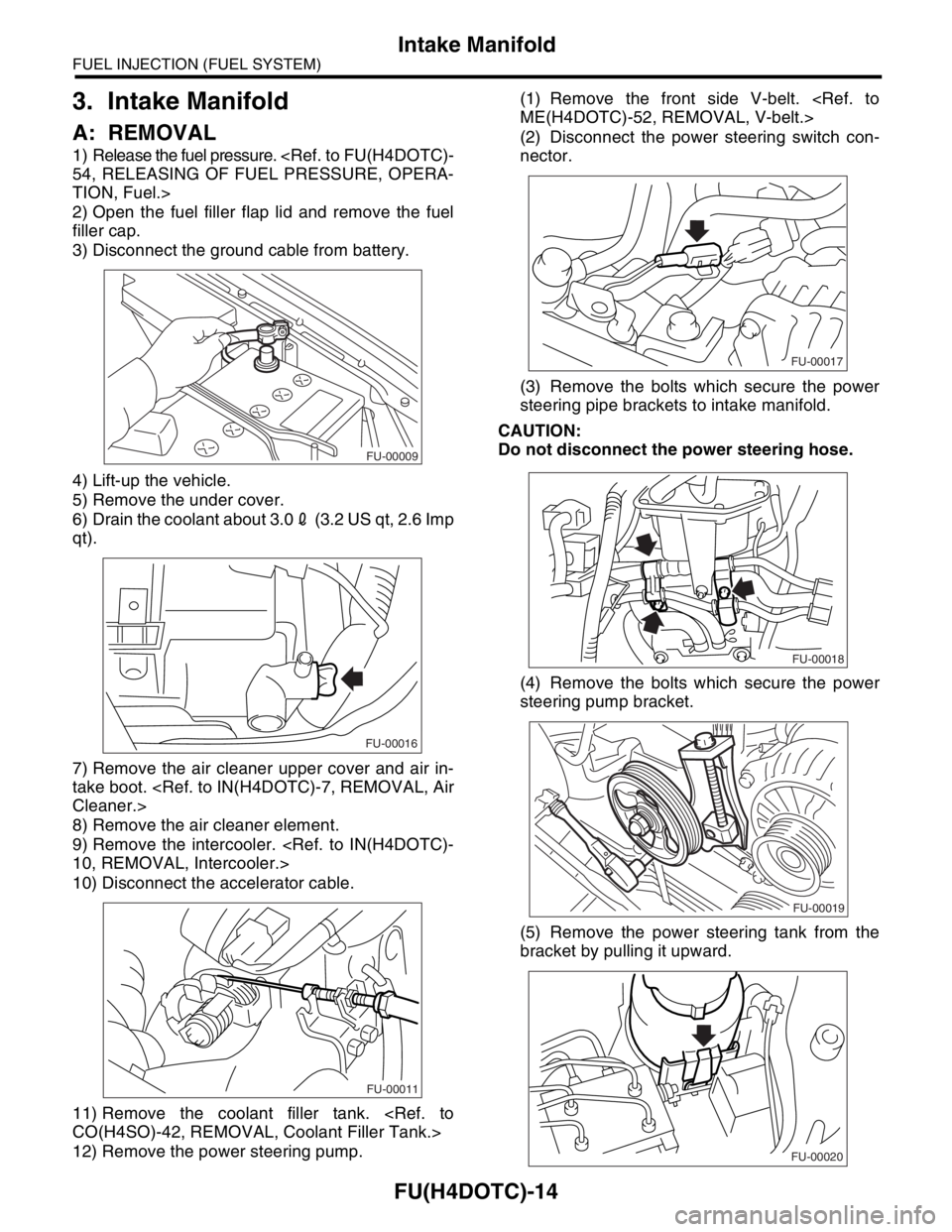
3. Intake Manifold
A: REMOVAL
1) Release the fuel pressure.
TION, Fuel.>
2) Open the fuel filler flap lid and remove the fuel
filler cap.
3) Disconnect the ground cable from battery.
4) Lift-up the vehicle.
5) Remove the under cover.
6) Drain the coolant about 3.02 (3.2 US qt, 2.6 Imp
qt).
7) Remove the air cleaner upper cover and air in-
take boot.
8) Remove the air cleaner element.
9) Remove the intercooler.
10) Disconnect the accelerator cable.
11) Remove the coolant filler tank.
12) Remove the power steering pump.(1) Remove the front side V-belt.
(2) Disconnect the power steering switch con-
nector.
(3) Remove the bolts which secure the power
steering pipe brackets to intake manifold.
CAUTION:
Do not disconnect the power steering hose.
(4) Remove the bolts which secure the power
steering pump bracket.
(5) Remove the power steering tank from the
bracket by pulling it upward.
FU-00009
FU-00016
FU-00011
FU-00017
FU-00018
FU-00019
FU-00020
Page 1375 of 2870

FU(H4DOTC)-20
FUEL INJECTION (FUEL SYSTEM)
Intake Manifold
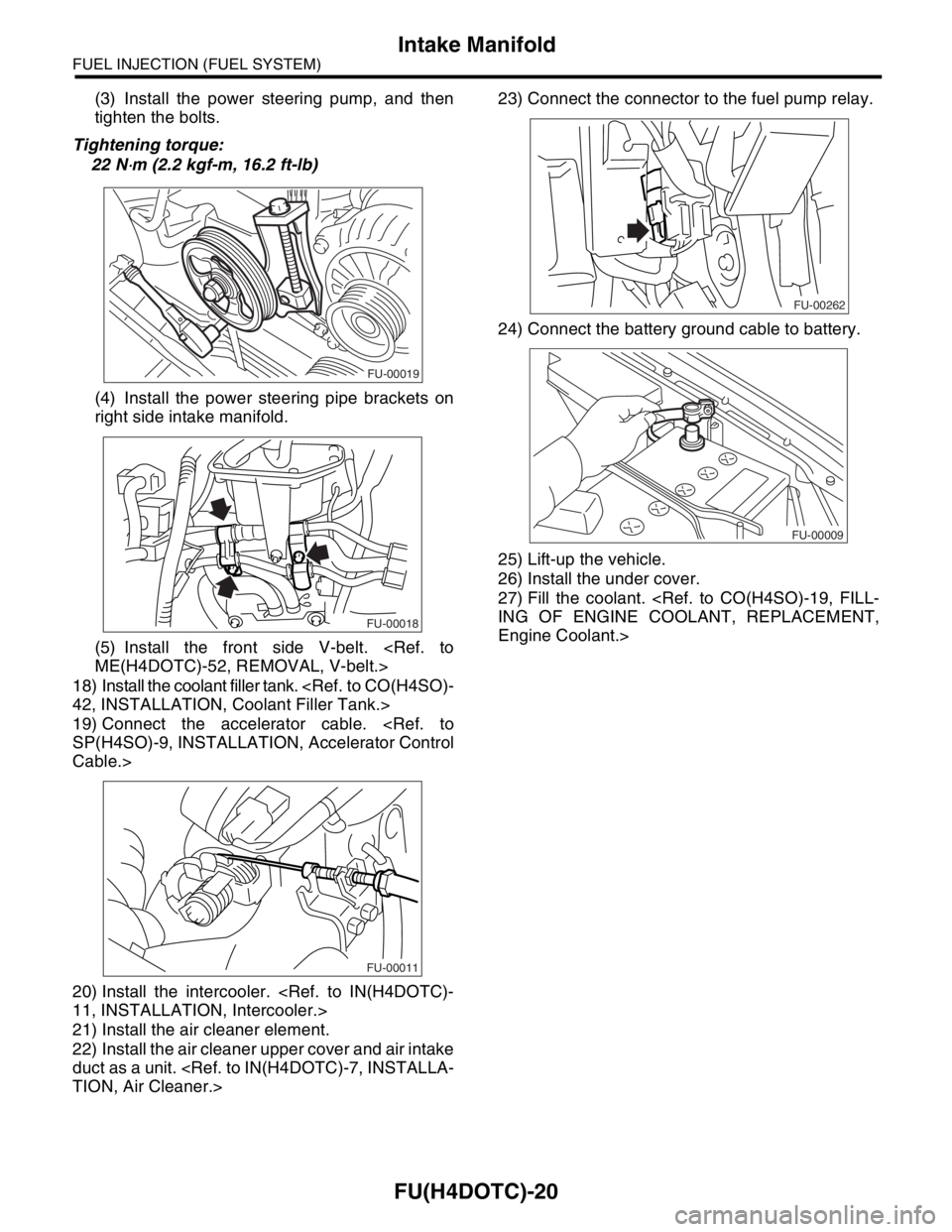
(3) Install the power steering pump, and then
tighten the bolts.
Tightening torque:
22 N
⋅m (2.2 kgf-m, 16.2 ft-lb)
(4) Install the power steering pipe brackets on
right side intake manifold.
(5) Install the front side V-belt.
18) Install the coolant filler tank.
19) Connect the accelerator cable.
Cable.>
20) Install the intercooler.
21) Install the air cleaner element.
22) Install the air cleaner upper cover and air intake
duct as a unit.
24) Connect the battery ground cable to battery.
25) Lift-up the vehicle.
26) Install the under cover.
27) Fill the coolant.
Engine Coolant.>
FU-00019
FU-00018
FU-00011
FU-00262
FU-00009
Page 1457 of 2870

MECHANICAL
ME(H4DOTC)
Page
1. General Description ....................................................................................2
2. Compression .............................................................................................31
3. Idle Speed .................................................................................................32
4. Ignition Timing ...........................................................................................33
5. Intake Manifold Vacuum............................................................................34
6. Engine Oil Pressure ..................................................................................35
7. Fuel Pressure ............................................................................................36
8. Valve Clearance ........................................................................................37
9. Engine Assembly ......................................................................................41
10. Engine Mounting .......................................................................................50
11. Preparation for Overhaul ...........................................................................51
12. V-belt .........................................................................................................52
13. Crank Pulley ..............................................................................................55
14. Timing Belt Cover......................................................................................57
15. Timing Belt Assembly................................................................................58
16. Cam Sprocket ...........................................................................................67
17. Crank Sprocket .........................................................................................68
18. Camshaft ...................................................................................................69
19. Cylinder Head Assembly ...........................................................................76
20. Cylinder Block ...........................................................................................84
21. Intake and Exhaust Valve .......................................................................115
22. Piston ......................................................................................................116
23. Connecting Rod ......................................................................................117
24. Crankshaft ...............................................................................................118
25. Engine Trouble in General ......................................................................119
26. Engine Noise ...........................................................................................124
Page 1458 of 2870

ME(H4DOTC)-2
MECHANICAL
General Description
1. General Description
A: SPECIFICATION
1. 2.0 L MODEL
NOTE:
STD: Standard I.D.: Inner Diameter O.D.: Outer Diameter OS: Oversize US: Undersize
EngineTy p eHorizontally opposed, liquid cooled, 4-cylinder, 4-stroke
gasoline engine
Valve arrangement Belt driven, double overhead camshaft, 4-valve/cylinder
Bore×Stroke mm (in) 92×75 (3.62×2.95)
Piston displacement
cm
3 (cu in)1,994 (121.67)
Compression ratio 8.0
Compression pres-
sure (at 200 — 300
rpm)kPa (kgf/cm
2, psi)981 — 1,177 (10 — 12, 142 — 171)
Number of piston rings Pressure ring: 2, Oil ring: 1
Intake valve timingOpeningMax. retard BTDC 3°
Min. advance BTDC 33°
ClosingMax. retard ABDC 33°
Min. advance ABDC 3°
Exhaust valve timingOpening BBDC 33°
Closing ATDC 3°
Valve clearanceIntake mm (in) 0.20±0.02 (0.0079±0.0008)
Exhaust mm (in) 0.35±0.02 (0.0138±0.0008)
Idling speed
[At neutral position on MT, or “P” or
“N” range on AT]
rpmNo loadMT: 700±100
AT : 7 0 0±100
A/C ONA/C Refrigerant pressure
(LOW)MT: 725±100
AT : 7 5 0±100
A/C Refrigerant pressure
(HIGH)MT: 800±100
AT : 8 2 5±100
Firing order 1 → 3 → 2 → 4
Ignition timing BTDC/rpm 12°±10°/700
Belt ten-
sion
adjusterProtrusion of adjuster rod 5.7 — 6.7 mm (0.224 — 0.264 in)
Belt ten-
sionerSpacer O.D. 17.955 — 17.975 mm (0.7069 — 0.7077 in)
Tensioner bush I.D. 18.0 — 18.08 mm (0.7087 — 0.7118 in)
Clearance between spacer and bushSTD 0.025 — 0.125 mm (0.0010 — 0.0049 in)
Limit 0.175 mm (0.0069 in)
Side clearance of spacerSTD 0.2 — 0.55 mm (0.0079 — 0.0217 in)
Limit 0.81 mm (0.0319 in)
Page 1462 of 2870

ME(H4DOTC)-6
MECHANICAL
General Description
2. 2.5 L MODEL
NOTE:
STD: Standard I.D.: Inner Diameter O.D.: Outer Diameter OS: Oversize US: Undersize
EngineModel2.5 L
Ty p eHorizontally opposed, liquid cooled, 4-cylinder,
4-stroke gasoline engine
Valve arrangement Belt driven, double overhead camshaft, 4-valve/cylinder
Bore×Stroke mm (in) 99.5×79.0 (3.92×3.11)
Piston displacement
cm
3 (cu in)2,457 (149.94)
Compression ratio 8.2
Compression pres-
sure (at 200 — 300
rpm)kPa (kgf/cm
2, psi)981 — 1,177 (10 — 12, 142 — 171)
Number of piston rings Pressure ring: 2, Oil ring: 1
Intake valve timingOpeningMax. retard ATDC 5°
Min. advance BTDC 15°
ClosingMax. retard ABDC 65°
Min. advance ABDC 45°
Exhaust valve timingOpening BBDC 55°
Closing ATDC 5°
Valve clearanceIntake mm (in) 0.20±0.02 (0.0079±0.0008)
Exhaust mm (in) 0.35±0.02 (0.0138±0.0008)
Idling speed
[At neutral position on MT, or “P” or “N”
range on AT]
rpmNo loadMT: 700±100
AT : 7 0 0±100
A/C ONA/C Refrigerant pressure
(LOW)MT: 725±100
AT : 7 5 0±100
A/C Refrigerant pressure
(HIGH)MT: 800±100
AT : 8 2 5±100
Firing order 1 → 3 → 2 → 4
Ignition timing BTDC/rpmMT model 17°±10°/700
AT model 17°±10°/700