2004 SUBARU FORESTER belt
[x] Cancel search: beltPage 1463 of 2870

ME(H4DOTC)-7
MECHANICAL
General Description
Belt ten-
sion
adjusterProtrusion of adjuster rod 5.7 — 6.7 mm (0.224 — 0.264 in)
Belt ten-
sionerSpacer O.D. 17.955 — 17.975 mm (0.7069 — 0.7077 in)
Tensioner bush I.D. 18.0 — 18.08 mm (0.7087 — 0.7118 in)
Clearance between spacer and bushSTD 0.025 — 0.125 mm (0.0010 — 0.0049 in)
Limit 0.175 mm (0.069 in)
Side clearance of spacerSTD 0.2 — 0.55 mm (0.0079 — 0.0217 in)
Limit 0.81 mm (0.0319 in)
CamshaftBend limit 0.020 mm (0.0079 in)
Thrust clearanceSTD 0.068 — 0.116 mm (0.0027 — 0.0046 in)
Limit 0.14 mm (0.0055 in)
Cam lobe heightIntakeSTD 46.55 — 46.65 mm (1.833 — 1.837 in)
Limit 46.45 mm (1.829 in)
ExhaustSTD 46.75 — 46.85 mm (1.841 — 1.844 in)
Limit 46.65 mm (1.837 in)
Journal O.D. STDFront 37.946 — 37.963 mm (1.4939 — 1.4946 in)
Center
rear29.946 — 29.963 mm (1.1790 — 1.1796 in)
Oil clearanceSTD 0.037 — 0.072 mm (0.0015 — 0.0028 in)
Limit 0.10 mm (0.0039 in)
Cylinder
headSurface warpage limit (mating with cylinder head) 0.05 mm (0.0020 in)
Surface grinding limit 0.3 mm (0.012 in)
Standard height 127.5 mm (5.02 in)
Va l ve s e a tRefacing angle 90°
Contacting widthIntakeSTD 1.0 mm (0.039 in)
Limit 1.7 mm (0.067 in)
ExhaustSTD 1.5 mm (0.059 in)
Limit 2.2 mm (0.087 in)
Valve guideInner diameter 6.000 — 6.012 mm (0.2362 — 0.2367 in)
Protrusion above head 15.8 — 16.2 mm (0.622 — 0.638 in)
Va l veHead edge thicknessIntakeSTD 1.2 mm (0.047 in)
Limit 0.8 mm (0.031 in)
ExhaustSTD 1.5 mm (0.059 in)
Limit 0.8 mm (0.031 in)
Stem diameterIntake 5.955 — 5.970 mm (0.2344 — 0.2350 in)
Exhaust 5.945 — 5.960 mm (0.2341 — 0.2346 in)
Stem oil clearanceSTDIntake 0.030 — 0.057 mm (0.0012 — 0.0022 in)
Exhaust 0.040 — 0.067 mm (0.0016 — 0.0026 in)
Limit — 0.15 mm (0.0059 in)
Overall lengthIntake 104.4 mm (4.110 in)
Exhaust 104.65 mm (4.120 in)
Va l ve
springFree length 47.32 mm (1.863 in)
Squareness 2.5°, 2.1 mm (0.083 in)
Tension/spring heightSet205 — 235 N (20.9 — 24.0 kgf, 46.1 — 52.8 lb)/
36.0 mm (1.417 in)
Lift426 — 490 N (43.4 — 50.0 kgf, 95.8 — 110 lb)/
26.50 mm (1.043 in)
Page 1466 of 2870
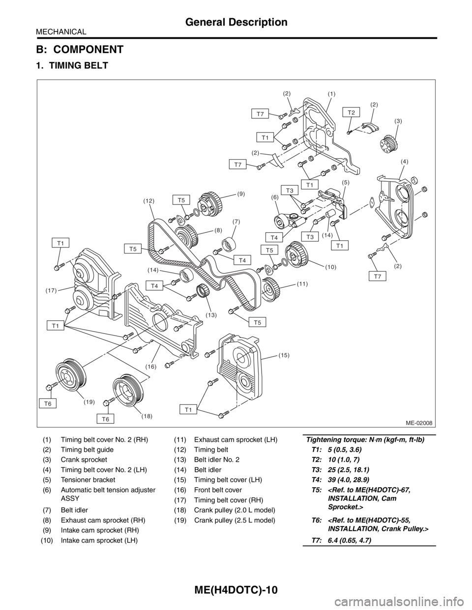
ME(H4DOTC)-10
MECHANICAL
General Description
B: COMPONENT
1. TIMING BELT
(1) Timing belt cover No. 2 (RH) (11) Exhaust cam sprocket (LH)Tightening torque: N⋅m (kgf-m, ft-lb)
(2) Timing belt guide (12) Timing beltT1: 5 (0.5, 3.6)
(3) Crank sprocket (13) Belt idler No. 2T2: 10 (1.0, 7)
(4) Timing belt cover No. 2 (LH) (14) Belt idlerT3: 25 (2.5, 18.1)
(5) Tensioner bracket (15) Timing belt cover (LH)T4: 39 (4.0, 28.9)
(6) Automatic belt tension adjuster
ASSY(16) Front belt coverT5:
Sprocket.> (17) Timing belt cover (RH)
(7) Belt idler (18) Crank pulley (2.0 L model)
(8) Exhaust cam sprocket (RH) (19) Crank pulley (2.5 L model)T6:
(9) Intake cam sprocket (RH)
(10) Intake cam sprocket (LH)T7: 6.4 (0.65, 4.7)
ME-02008
T5
T1T6(7)(6)
(10)
(19)(5)
(14)(2)
(3)
T2
(4)
(1)(2)
(2)
T7
T4
T3
T3
T4
T5
T4
T5T1
T7(11)
(15)
(17)
(2)
(9)
(8)
(13) (14) (12)
T1
T1
T7
T1
T1
T5
(16)
T6(18)
Page 1478 of 2870

ME(H4DOTC)-22
MECHANICAL
General Description
C: CAUTION
Wear working clothing, including a cap, protec-
tive goggles, and protective shoes during opera-
tion.
Remove contamination including dirt and corro-
sion before removal, installation or disassembly.
Keep the disassembled parts in order and pro-
tect them from dust or dirt.
Before removal, installation or disassembly, be
sure to clarify the failure. Avoid unnecessary re-
moval, installation, disassembly, and replacement.
Be careful not to burn yourself, because each
part in the vehicle is hot after running.
Be sure to tighten fasteners including bolts and
nuts to the specified torque.
Place shop jacks or rigid racks at the specified
points.
Before disconnecting electrical connectors of
sensors or units, be sure to disconnect the ground
cable from battery.
All parts should be thoroughly cleaned, paying
special attention to the engine oil passages, pis-
tons and bearings.
Rotating parts and sliding parts such as piston,
bearing and gear should be coated with oil prior to
assembly.
Be careful not to let oil, grease or coolant contact
the timing belt, clutch disc and flywheel.
All removed parts, if to be reused, should be re-
installed in the original positions and directions.
Bolts, nuts and washers should be replaced with
new ones as required.
Even if necessary inspections have been made
in advance, proceed with assembly work while
making rechecks.
Remove or install the engine in an area where
chain hoists, lifting devices, etc. are available for
ready use.
Be sure not to damage coated surfaces of body
panels with tools or stain seats and windows with
coolant or oil. Place a cover over fenders, as re-
quired, for protection.
Prior to starting work, prepare the following:
Service tools, clean cloth, containers to catch cool-
ant and oil, wire ropes, chain hoist, transmission
jacks, etc.
Lift-up or lower the vehicle when necessary.
Make sure to support the correct positions.
Page 1486 of 2870
ME(H4DOTC)-30
MECHANICAL
General Description
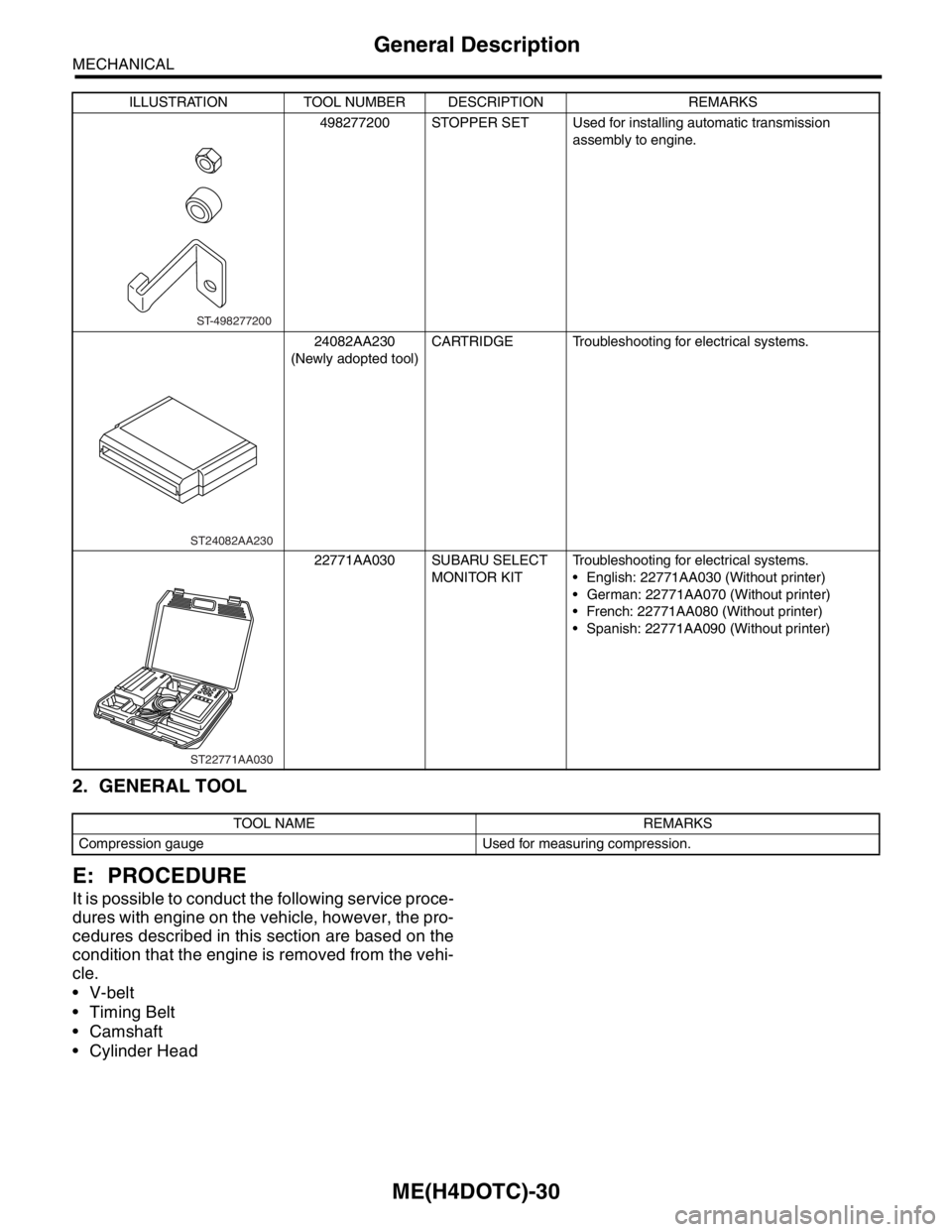
2. GENERAL TOOL
E: PROCEDURE
It is possible to conduct the following service proce-
dures with engine on the vehicle, however, the pro-
cedures described in this section are based on the
condition that the engine is removed from the vehi-
cle.
V-belt
Timing Belt
Camshaft
Cylinder Head
498277200 STOPPER SET Used for installing automatic transmission
assembly to engine.
24082AA230
(Newly adopted tool)CARTRIDGE Troubleshooting for electrical systems.
22771AA030 SUBARU SELECT
MONITOR KITTroubleshooting for electrical systems.
English: 22771AA030 (Without printer)
German: 22771AA070 (Without printer)
French: 22771AA080 (Without printer)
Spanish: 22771AA090 (Without printer)
TOOL NAME REMARKS
Compression gauge Used for measuring compression.ILLUSTRATION TOOL NUMBER DESCRIPTION REMARKS
ST-498277200
ST24082AA230
ST22771AA030
Page 1493 of 2870
ME(H4DOTC)-37
MECHANICAL
Valve Clearance
8. Valve Clearance
A: INSPECTION
Inspection and adjustment of the valve clearance
should be performed while engine is cold.
1) Set the vehicle on a lift.
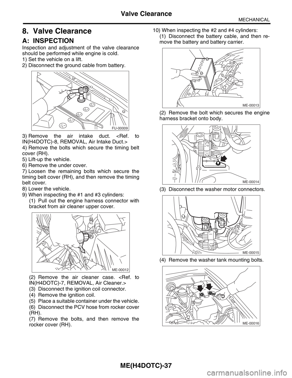
2) Disconnect the ground cable from battery.
3) Remove the air intake duct.
4) Remove the bolts which secure the timing belt
cover (RH).
5) Lift-up the vehicle.
6) Remove the under cover.
7) Loosen the remaining bolts which secure the
timing belt cover (RH), and then remove the timing
belt cover.
8) Lower the vehicle.
9) When inspecting the #1 and #3 cylinders:
(1) Pull out the engine harness connector with
bracket from air cleaner upper cover.
(2) Remove the air cleaner case.
(3) Disconnect the ignition coil connector.
(4) Remove the ignition coil.
(5) Place a suitable container under the vehicle.
(6) Disconnect the PCV hose from rocker cover
(RH).
(7) Remove the bolts, and then remove the
rocker cover (RH).10) When inspecting the #2 and #4 cylinders:
(1) Disconnect the battery cable, and then re-
move the battery and battery carrier.
(2) Remove the bolt which secures the engine
harness bracket onto body.
(3) Disconnect the washer motor connectors.
(4) Remove the washer tank mounting bolts.
FU-00009
ME-00012
ME-00013
ME-00014
ME-00015
ME-00016
Page 1498 of 2870

MECHANICAL
ME(H4DOTC)
Page
1. General Description ....................................................................................2
2. Compression .............................................................................................31
3. Idle Speed .................................................................................................32
4. Ignition Timing ...........................................................................................33
5. Intake Manifold Vacuum............................................................................34
6. Engine Oil Pressure ..................................................................................35
7. Fuel Pressure ............................................................................................36
8. Valve Clearance ........................................................................................37
9. Engine Assembly ......................................................................................41
10. Engine Mounting .......................................................................................50
11. Preparation for Overhaul ...........................................................................51
12. V-belt .........................................................................................................52
13. Crank Pulley ..............................................................................................55
14. Timing Belt Cover......................................................................................57
15. Timing Belt Assembly................................................................................58
16. Cam Sprocket ...........................................................................................67
17. Crank Sprocket .........................................................................................68
18. Camshaft ...................................................................................................69
19. Cylinder Head Assembly ...........................................................................76
20. Cylinder Block ...........................................................................................84
21. Intake and Exhaust Valve .......................................................................115
22. Piston ......................................................................................................116
23. Connecting Rod ......................................................................................117
24. Crankshaft ...............................................................................................118
25. Engine Trouble in General ......................................................................119
26. Engine Noise ...........................................................................................124
Page 1500 of 2870
ME(H4DOTC)-42
MECHANICAL
Engine Assembly
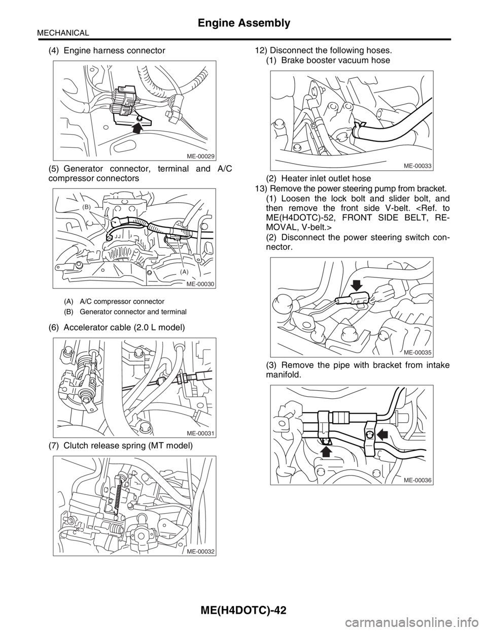
(4) Engine harness connector
(5) Generator connector, terminal and A/C
compressor connectors
(6) Accelerator cable (2.0 L model)
(7) Clutch release spring (MT model)12) Disconnect the following hoses.
(1) Brake booster vacuum hose
(2) Heater inlet outlet hose
13) Remove the power steering pump from bracket.
(1) Loosen the lock bolt and slider bolt, and
then remove the front side V-belt.
MOVAL, V-belt.>
(2) Disconnect the power steering switch con-
nector.
(3) Remove the pipe with bracket from intake
manifold.
(A) A/C compressor connector
(B) Generator connector and terminal
ME-00029
ME-00030
(A) (B)
ME-00031
ME-00032
ME-00033
ME-00035
ME-00036
Page 1506 of 2870
ME(H4DOTC)-48
MECHANICAL
Engine Assembly
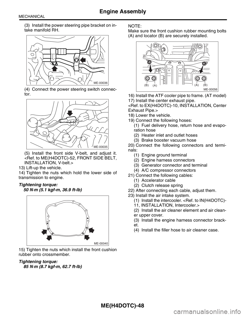
(3) Install the power steering pipe bracket on in-
take manifold RH.
(4) Connect the power steering switch connec-
tor.
(5) Install the front side V-belt, and adjust it.
13) Lift-up the vehicle.
14) Tighten the nuts which hold the lower side of
transmission to engine.
Tightening torque:
50 N
⋅m (5.1 kgf-m, 36.9 ft-lb)
15) Tighten the nuts which install the front cushion
rubber onto crossmember.
Tightening torque:
85 N
⋅m (8.7 kgf-m, 62.7 ft-lb)NOTE:
Make sure the front cushion rubber mounting bolts
(A) and locator (B) are securely installed.
16) Install the ATF cooler pipe to frame. (AT model)
17) Install the center exhaust pipe.
18) Lower the vehicle.
19) Connect the following hoses:
(1) Fuel delivery hose, return hose and evapo-
ration hose
(2) Heater inlet and outlet hoses
(3) Brake booster vacuum hose
20) Connect the following connectors and termi-
nals:
(1) Engine ground terminal
(2) Engine harness connectors
(3) Generator connector and terminal
(4) A/C compressor connectors
21) Connect the following cables:
(1) Accelerator cable
(2) Clutch release spring
22) After connecting each cable, adjust them.
23) Install the air intake system.
(1) Install the intercooler.
(2) Install the air cleaner element and air clean-
er upper cover.
(3) Install the engine harness connector brack-
et.
(4) Install the filler hose to air cleaner case.
ME-00036
ME-00035
ME-00040
ME-00056
(A)
(A)(B)
(B)