Page 1015 of 2870
CO(H4SO)-32
COOLING
Radiator
2. TURBO MODEL
1) Install the radiator under cover to radiator.
2) Attach the radiator lower cushions to holes on
the vehicle.
3) Install the radiator to vehicle.
NOTE:
Fit pins on the lower side of radiator into cushions
on body side.
4) Install the radiator upper brackets, and then
tighten the bolts.
Tightening torque:
18 N
⋅m (1.8 kgf-m, 13.0 ft-lb)5) Connect the power steering hose to radiator.
6) Connect the radiator inlet hose (A) and water
tank hose (B).
7) Install the reservoir tank.
Tightening torque:
4.9 N
⋅m (0.50 kgf-m, 3.6 ft-lb)
8) Connect the over flow hose.
9) Install the V-belt cover.
10) Lift-up the vehicle.
11) Connect the ATF cooler hoses. (AT model).
CO-00070
CO-00041
CO-00040
CO-00037
CO-00039
(A) (B)
CO-00015
SC-00096
Page 1019 of 2870
CO(H4SO)-36
COOLING
Radiator Main Fan and Fan Motor
2. TURBO MODEL
1) Set the vehicle on a lift.
2) Disconnect the ground cable from battery.
3) Remove the radiator upper bracket. (AT model)
4) Lift-up the vehicle.
5) Remove the under cover.
6) Drain the engine coolant approx. 12(1.06 US qt,
0.88 Imp qt).
OF ENGINE COOLANT, REPLACEMENT, Engine
Coolant.>
7) Disconnect the radiator main fan motor connec-
tor (A) and sub fan motor connector (B).8) Remove the radiator under cover securing bolt.
(AT model)
9) Pull the radiator lower hose upward to space ra-
diator from radiator under cover. Remove the ATF
hose to radiator fan motor assembly two clips. (AT
model)
10) Lower the vehicle.
11) Remove the V-belt cover.
12) Disconnect the overflow hose.
13) Remove the reservoir tank.
14) Remove the radiator main fan motor assembly
securing bolt.
FU-00009
CO-00036
CO-00013
(A)(B)
CO-00070
CO-00143
CO-00015
CO-00064
Page 1022 of 2870

CO(H4SO)-39
COOLING
Radiator Main Fan and Fan Motor
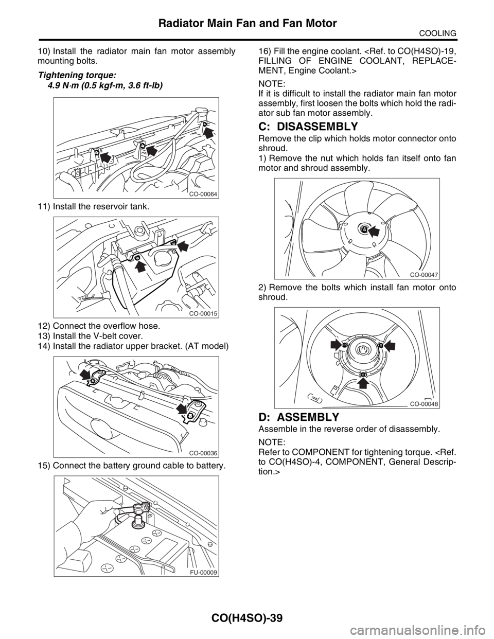
10) Install the radiator main fan motor assembly
mounting bolts.
Tightening torque:
4.9 N
⋅m (0.5 kgf-m, 3.6 ft-lb)
11) Install the reservoir tank.
12) Connect the overflow hose.
13) Install the V-belt cover.
14) Install the radiator upper bracket. (AT model)
15) Connect the battery ground cable to battery.16) Fill the engine coolant.
FILLING OF ENGINE COOLANT, REPLACE-
MENT, Engine Coolant.>
NOTE:
If it is difficult to install the radiator main fan motor
assembly, first loosen the bolts which hold the radi-
ator sub fan motor assembly.
C: DISASSEMBLY
Remove the clip which holds motor connector onto
shroud.
1) Remove the nut which holds fan itself onto fan
motor and shroud assembly.
2) Remove the bolts which install fan motor onto
shroud.
D: ASSEMBLY
Assemble in the reverse order of disassembly.
NOTE:
Refer to COMPONENT for tightening torque.
to CO(H4SO)-4, COMPONENT, General Descrip-
tion.>
CO-00064
CO-00015
CO-00036
FU-00009
CO-00047
CO-00048
Page 1026 of 2870

CO(H4SO)-43
COOLING
Engine Cooling System Trouble in General
12.Engine Cooling System Trouble in General
A: INSPECTION
Trouble Possible cause Corrective action
Over-heatinga. Insufficient engine coolantReplenish the engine coolant, inspect for leakage, and
repair.
b. Loose timing belt Repair or replace the timing belt tensioner.
c. Oil on drive belt Replace.
d. Malfunction of thermostat Replace.
e. Malfunction of water pump Replace.
f. Clogged engine coolant passage Clean.
g. Improper ignition timingInspect and repair the ignition control system.
nostics Procedure.>
h. Clogged or leaking radiator Clean or repair, or replace.
i. Improper engine oil in engine coolant Replace the engine coolant.
j. Air/fuel mixture ratio too leanInspect and repair the fuel injection system.
nostics Procedure.>
k. Excessive back pressure in exhaust system Clean or replace.
l. Insufficient clearance between piston and cylinder Adjust or replace.
m. Slipping clutch Repair or replace.
n. Dragging brake Adjust.
o. Defective thermostat Replace.
p. Malfunction of radiator fanInspect the radiator fan relay, engine coolant tempera-
ture sensor or radiator motor and replace there.
Over-coolinga. Atmospheric temperature extremely low Partly cover the radiator front area.
b. Defective thermostat Replace.
Engine coolant
leaks.a. Loosened or damaged connecting units on hoses Repair or replace.
b. Leakage from water pump Replace.
c. Leakage from water pipe Repair or replace.
d. Leakage around cylinder head gasket Retighten the cylinder head bolts or replace gasket.
e. Damaged or cracked cylinder head and crankcase Repair or replace.
f. Damaged or cracked thermostat case Repair or replace.
g. Leakage from radiator Repair or replace.
Noisea. Defective drive belt Replace.
b. Defective radiator fan Replace.
c. Defective water pump bearing Replace the water pump.
d. Defective water pump mechanical seal Replace the water pump.
Page 1040 of 2870
LU(H4SO)-12
LUBRICATION
Oil Pump
4. Oil Pump
A: REMOVAL
1) Disconnect the ground cable from battery.
2) Lift-up the vehicle.
3) Remove the under cover.
4) Remove the bolts which install water pipe of oil
cooler to oil pump. (Turbo model)
5) Remove the water pipe and hoses between oil
cooler and water pump. (Turbo model)
6) Remove the radiator.
REMOVAL, Radiator.>7) Remove the crankshaft position sensor.
8) Remove the V-belts.
to ME(H4DOTC)-52, REMOVAL, V-belt.>
9) Remove the rear side V-belt tensioner.
10) Remove the crankshaft pulley by using ST.
ST 499977400 CRANK PULLEY WRENCH
(2.0 L model)
ST 499977100 CRANK PULLEY WRENCH
(2.5 L model)
11) Remove the water pump.
21, REMOVAL, Water Pump.>
FU-00009
LU-00137
LU-00010
LU-00046
LU-00011
LU-00012
Page 1041 of 2870

LU(H4SO)-13
LUBRICATION
Oil Pump
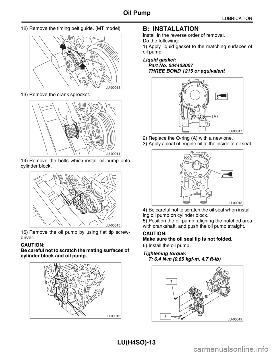
12) Remove the timing belt guide. (MT model)
13) Remove the crank sprocket.
14) Remove the bolts which install oil pump onto
cylinder block.
15) Remove the oil pump by using flat tip screw-
driver.
CAUTION:
Be careful not to scratch the mating surfaces of
cylinder block and oil pump.B: INSTALLATION
Install in the reverse order of removal.
Do the following:
1) Apply liquid gasket to the matching surfaces of
oil pump.
Liquid gasket:
Part No. 004403007
THREE BOND 1215 or equivalent
2) Replace the O-ring (A) with a new one.
3) Apply a coat of engine oil to the inside of oil seal.
4) Be careful not to scratch the oil seal when install-
ing oil pump on cylinder block.
5) Position the oil pump, aligning the notched area
with crankshaft, and push the oil pump straight.
CAUTION:
Make sure the oil seal lip is not folded.
6) Install the oil pump.
Tightening torque:
T: 6.4 N
⋅m (0.65 kgf-m, 4.7 ft-lb)
LU-00013
LU-00014
LU-00015
LU-00016
LU-00017
(A)
LU-00018
LU-00019
T
T
Page 1090 of 2870
SC(H4SO)-15
STARTING/CHARGING SYSTEM
Generator
3. Generator
A: REMOVAL
1) Disconnect the ground cable from battery.
2) Disconnect the connector and terminal from
generator.
Non-turbo model
Turbo model
3) Remove the V-belt cover.
Non-turbo model Turbo model
4) Remove the front side V-belt.
MOVAL, V-belt.> or
FRONT SIDE BELT, REMOVAL, V-belt.>
5) Remove the bolts which install generator onto
bracket.
B: INSTALLATION
Install in the reverse order of removal.
CAUTION:
Check and adjust the V-belt tension.
ME(H4SO)-44, INSPECTION, V-belt.> or
ME(H4DOTC)-53, INSPECTION, V-belt.>
FU-00009
SC-00029
SC-00143
SC-00031
SC-00096
SC-00032
SC-00032
Page 1242 of 2870

EN(H4SO)-144
ENGINE (DIAGNOSTIC)
Diagnostic Procedure with Diagnostic Trouble Code (DTC)
6 CHECK POWER SUPPLY LINE.
1) Turn the ignition switch to ON.
2) Measure the voltage between fuel injector
and engine ground on faulty cylinders.
Connector & terminal
#1 (E5) No. 2 (+) — Engine ground (
−):
#2 (E16) No. 2 (+) — Engine ground (
−):
#3 (E6) No. 2 (+) — Engine ground (
−):
#4 (E17) No. 2 (+) — Engine ground (
−):Is the voltage more than 10 V? Repair poor con-
tact in all connec-
tors in fuel injector
circuit.Repair harness
and connector.
N
OTE:
In this case repair
the following:
Open circuit in
harness between
main relay and fuel
injector connector
on faulty cylinders
Poor contact in
coupling connector
Poor contact in
main relay connec-
tor
Poor contact in
fuel injector con-
nector on faulty
cylinders
7 CHECK HARNESS BETWEEN FUEL INJEC-
TOR AND ECM CONNECTOR.
1) Turn the ignition switch to OFF.
2) Disconnect the connector from fuel injector
on faulty cylinder.
3) Turn the ignition switch to ON.
4) Measure the voltage between ECM con-
nector and chassis ground on faulty cylinders.
Connector & terminal
#1 (B134) No. 34 (+) — Chassis ground (
−):
#2 (B134) No. 23 (+) — Chassis ground (
−):
#3 (B134) No. 22 (+) — Chassis ground (
−):
#4 (B134) No. 8 (+) — Chassis ground (
−):Is the voltage more than 10 V? Repair battery
short circuit in har-
ness between
ECM and fuel
injector. After
repair, replace the
ECM.
FU(H4SO)-44,
Engine Control
Module (ECM).>Go to step 8.
8 CHECK FUEL INJECTOR.
1) Turn the ignition switch to OFF.
2) Measure the resistance between fuel injec-
tor terminals on faulty cylinder.
Te r m i n a l s
No. 1 — No. 2:Is the resistance less than 1
Ω?Replace the faulty
fuel injector
to FU(H4SO)-35,
Fuel Injector.> and
ECM.
FU(H4SO)-44,
Engine Control
Module (ECM).>Go to step 9.
9 CHECK INSTALLATION OF CAMSHAFT PO-
SITION SENSOR/CRANKSHAFT POSITION
SENSOR.Is the installation of camshaft
position sensor or crankshaft
position sensor loosened?Tighten camshaft
position sensor or
crankshaft posi-
tion sensor.Go to step 10.
10 CHECK CRANK SPROCKET.
Remove the timing belt cover.Is the crank sprocket rusted or
does it have broken teeth?Replace the crank
sprocket.
ME(H4SO)-55,
Crank Sprocket.>Go to step 11.
11 CHECK INSTALLATION CONDITION OF
TIMING BELT.
Turn the crankshaft using ST, and align align-
ment mark on crank sprocket with alignment
mark on cylinder block.
ST 499987500 CRANKSHAFT SOCKETIs the timing belt dislocated
from its proper position?Repair installation
condition of timing
belt.
ME(H4SO)-48,
Timing Belt.>Go to step 12.
12 CHECK FUEL LEVEL.Is the fuel meter indication
higher than the “Lower” level?Go to step 13.Replenish fuel so
fuel meter indica-
tion is higher than
the “Lower” level.
After replenishing
fuel, Go to step 13. Step Check Yes No