Page 111 of 2870

AB-11
AIRBAG SYSTEM
Airbag Connector
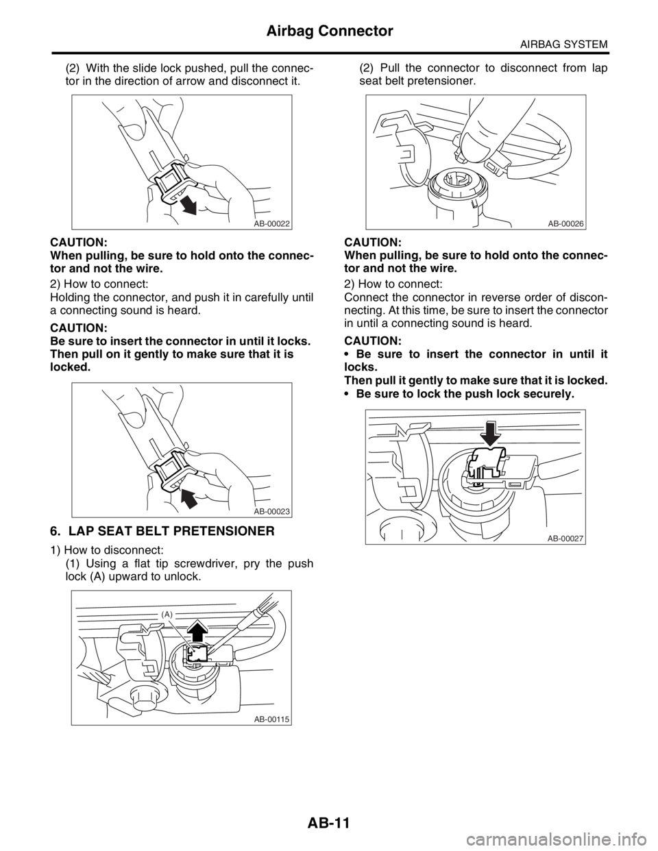
(2) With the slide lock pushed, pull the connec-
tor in the direction of arrow and disconnect it.
CAUTION:
When pulling, be sure to hold onto the connec-
tor and not the wire.
2) How to connect:
Holding the connector, and push it in carefully until
a connecting sound is heard.
CAUTION:
Be sure to insert the connector in until it locks.
Then pull on it gently to make sure that it is
locked.
6. LAP SEAT BELT PRETENSIONER
1) How to disconnect:
(1) Using a flat tip screwdriver, pry the push
lock (A) upward to unlock.(2) Pull the connector to disconnect from lap
seat belt pretensioner.
CAUTION:
When pulling, be sure to hold onto the connec-
tor and not the wire.
2) How to connect:
Connect the connector in reverse order of discon-
necting. At this time, be sure to insert the connector
in until a connecting sound is heard.
CAUTION:
Be sure to insert the connector in until it
locks.
Then pull it gently to make sure that it is locked.
Be sure to lock the push lock securely.
AB-00022
AB-00023
AB-00115
(A)
AB-00026
AB-00027
Page 112 of 2870

AB-12
AIRBAG SYSTEM
Inspection Locations After a Collision
3. Inspection Locations After a
Collision
A: REPLACEMENT
When airbag system is deployed, replace the fol-
lowing parts.
1. FRONT COLLISION
1) Driver’s airbag module
2) Passenger’s airbag module
3) Driver’s seat belt (pretensioner, lap seat belt pre-
tensioner)
4) Passenger’s seat belt (pretensioner)
5) Airbag control module
6) Front sub-sensor
7) Roll connector
2. SIDE COLLISION
1) Airbag control module
2) Side airbag module (operating side seat bag)
3) Side airbag sensor (operating side)
3. INSPECTION OF OTHER PARTS
Check for the following parts, replace the damaged
parts with new ones.
1) Steering wheel and steering shaft
Check the steering wheel and steering shaft for
mounting condition and deflection of axial and radi-
al direction. Check the steering shaft for deflection
of axial direction with tilt lever released. (After a col-
lision, absorbing part of steering shaft may inflate.)
2) Check the direct type connector of driver’s air-
bag module, pretensioner, etc. for damage, and
also check each harness for pinch and connector
damage. If damage is found, replace the harness
as a unit.
B: INSPECTION
If the vehicle is involved in a collision on any side,
even if it is a slight collision, be sure to check the
following system parts.
1. DRIVER’S AIRBAG MODULE
1) Check for the following, and replace damaged
parts with new ones.
Airbag module is cracked or deformed.
Harness and/or connector is cracked, deformed
or open. Lead wire is exposed.
The module surface is fouled with grease, oil,
water or cleaning solvent.
2) When installing a new driver’s airbag module,
check the following. If necessary, install a new air-
bag module and steering wheel.
The steering wheel is in the way, making it diffi-
cult to install the airbag module. The clearance between the driver’s airbag mod-
ule and steering wheel is not constant.
The steering wheel deformation in axial and radi-
al directions exceed limits.
Specifications:
Height deflection A
Less than 6 mm (0.24 in)
O.D. deflection L
Less than 17 mm (0.67 in)
2. PASSENGER’S AIRBAG MODULE
Check for the following, and replace damaged
parts with new ones.
Airbag module is cracked or deformed.
Harness and/or connector is cracked, deformed
or open. Lead wire is exposed.
Mounting bracket is cracked or deformed.
3. SIDE AIRBAG MODULE
Check for the following, and replace damaged
parts with new ones.
Front seat is damaged or deformed.
Harness and/or connector is cracked, deformed
or open.
Lead wire is exposed.
4. AIRBAG CONTROL MODULE
Check for the following, and replace damaged
parts with new ones.
Control module is cracked or deformed.
Mounting bracket is cracked or deformed.
Connector is scratched or deformed.
Airbag is deployed.
Side airbag is deployed.
AB-00028
L
A
Page 119 of 2870
AB-19
AIRBAG SYSTEM
Side Airbag Sensor
8. Side Airbag Sensor
A: REMOVAL
1) Turn the ignition switch to OFF.
2) Disconnect the ground cable from battery, and
wait for at least 20 seconds before starting work.
3) Remove the outer belt (FRONT).
10, FRONT OUTER BELT, REMOVAL, Front Seat
Belt.>
4) Detach the side airbag sensor, and then discon-
nect the airbag connector.
B: INSTALLATION
CAUTION:
Use new TORX® bolts T30 when reassembling.
Install in the reverse order of removal.
Tightening torque:
Refer to “COMPONENT” in “General Descrip-
tion”
NENT, General Description.>
C: INSPECTION
Check for the following, and replace damaged
parts with new parts.
Bracket connector for side airbag sensor is dam-
aged.
Side airbag is deployed.
AB-00036
Page 131 of 2870

FUJI HEAVY INDUSTRIES LTD. G8080GE7
2004 FORESTER SERVICE MANUAL QUICK REFERENCE INDEX
BODY SECTION
This service manual has been prepared
to provide SUBARU service personnel
with the necessary information and data
for the correct maintenance and repair
of SUBARU vehicles.
This manual includes the procedures
for maintenance, disassembling, reas-
sembling, inspection and adjustment of
components and diagnostics for guid-
ance of experienced mechanics.
Please peruse and utilize this manual
fully to ensure complete repair work for
satisfying our customers by keeping
their vehicle in optimum condition.
When replacement of parts during
repair work is needed, be sure to use
SUBARU genuine parts.
All information, illustration and specifi-
cations contained in this manual are
based on the latest product information
available at the time of publication
approval.HVAC SYSTEM
(HEATER, VENTILATOR AND A/C)AC
HVAC SYSTEM (AUTO A/C)
(DIAGNOSTIC)AC
AIRBAG SYSTEM AB
AIRBAG SYSTEM (DIAGNOSTIC) AB
SEAT BELT SYSTEM SB
LIGHTING SYSTEM LI
WIPER AND WASHER SYSTEM WW
ENTERTAINMENT ET
COMMUNICATION SYSTEM COM
GLASS/WINDOW/MIRROR GW
BODY STRUCTURE BS
INSTRUMENTATION/DRIVER INFO IDI
SEAT SE
SECURITY AND LOCK SL
SUNROOF/T-TOP/CONVERTIBLE TOP
(SUNROOF)SR
EXTERIOR/INTERIOR TRIM EI
EXTERIOR BODY PANEL EB
Page 144 of 2870
AB-12
AIRBAG SYSTEM (DIAGNOSTIC)
General Description
TEST HARNESS L
ILLUSTRATION TOOL NUMBER DESCRIPTION REMARKS
98299FE000 TEST HARNESS L Used when measuring voltage, resistance of
seat belt pretensioner.
3L
1L2L
ST98299FE000
AB-00430
3L
1
2 5
6
3
4
1L 2L
12
21
3 12
6
453L
2L1L1
2
Page 147 of 2870
AB-15
AIRBAG SYSTEM (DIAGNOSTIC)
General Description
TEST HARNESS N
ILLUSTRATION TOOL NUMBER DESCRIPTION REMARKS
98299SA000 TEST HARNESS N Used when measuring voltage, resistance of
driver’s airbag module and seat belt preten-
sioner.
2N
1N
ST98299SA000
AB-00675
2N1N
1
2
1
2
1
22
1
1N
2N
Page 151 of 2870

AB-19
AIRBAG SYSTEM (DIAGNOSTIC)
Electrical Components Location
4. Electrical Components Location
A: LOCATION
1. LHD MODEL
(a) To body harness (b) To seat belt pretensioner (LH) (c) To seat belt pretensioner (RH)
(1) Front sub sensor (LH) (6) Passenger’s airbag inflator (12) Side airbag sensor (LH)
(2) Front sub sensor (RH) (7) Roll connector (13) Side airbag sensor (RH)
(3) Front sub sensor harness (LH) (8) Airbag main harness (14) Side airbag inflator (LH)
(4) Front sub sensor harness (RH) (9) Driver’s airbag inflator (15) Side airbag inflator (RH)
(5)
Airbag control module with built-in
safety and electric sensor(10) Side airbag harness (LH)
(11) Side airbag harness (RH)
Connector
No.(AB1) (AB2) (AB3) (AB4) (AB7) (AB8) (AB9) (AB10) (AB11) (AB12) (AB13) (AB14)
Pole 622841212242422
Color Yellow Yellow Yellow Yellow Yellow Yellow Yellow Yellow Yellow Yellow Yellow Yellow
Male/Female Male Female Female Female Female Female Female Female Female Female Female Male
Connector
No.(AB15) (AB18) (AB19) (AB20) (AB21) (AB26)
Pole 222222
Color Yellow Yellow Yellow Yellow Yellow Yellow
Male/Female Female Female Female Female Female Male
AB-00737
(1)
(2)
(3)
(7) (a)
(9)
(14)
(15)
(13) (11)
(c) (6)
(5)
(8)
(10)
(b)
(12)(4)
AB18
B31
AB1
AB12
AB20AB19
AB10
AB3
AB8
AB15
AB7
AB9
AB4
AB26
AB2
AB21
AB14
AB13
AB11
Page 152 of 2870

AB-20
AIRBAG SYSTEM (DIAGNOSTIC)
Electrical Components Location
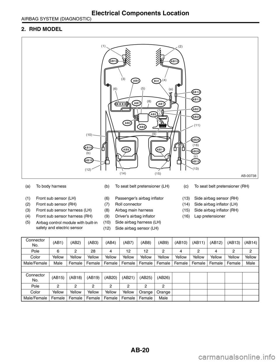
2. RHD MODEL
(a) To body harness (b) To seat belt pretensioner (LH) (c) To seat belt pretensioner (RH)
(1) Front sub sensor (LH) (6) Passenger’s airbag inflator (13) Side airbag sensor (RH)
(2) Front sub sensor (RH) (7) Roll connector (14) Side airbag inflator (LH)
(3) Front sub sensor harness (LH) (8) Airbag main harness (15) Side airbag inflator (RH)
(4) Front sub sensor harness (RH) (9) Driver’s airbag inflator (16) Lap pretensioner
(5)
Airbag control module with built-in
safety and electric sensor(10) Side airbag harness (LH)
(12) Side airbag sensor (LH)
Connector
No.(AB1) (AB2) (AB3) (AB4) (AB7) (AB8) (AB9) (AB10) (AB11) (AB12) (AB13) (AB14)
Pole 622841212242422
Color Yellow Yellow Yellow Yellow Yellow Yellow Yellow Yellow Yellow Yellow Yellow Yellow
Male/Female Male Female Female Female Female Female Female Female Female Female Female Male
Connector
No.(AB15) (AB18) (AB19) (AB20) (AB21) (AB25) (AB26)
Pole 2222222
Color Yellow Yellow Yellow Yellow Yellow Orange Orange
Male/Female Female Female Female Female Female Female Male
AB-00738
(1)
(2)
(5)
(6)
(8)
(7)
(11)
(13)
(12)(10)
(b)
(c) (a)
(9)
(14)
(15)
(3)(4)
(16)
AB14
AB15
AB13
AB26
AB21
B31
AB2
AB25
AB20
AB12
AB18
AB7AB1
AB3AB8
AB19
AB10
AB11AB9
AB4