2004 SUBARU FORESTER oil pressure
[x] Cancel search: oil pressurePage 806 of 2870
FU(H4SO)-24
FUEL INJECTION (FUEL SYSTEM)
Intake Manifold
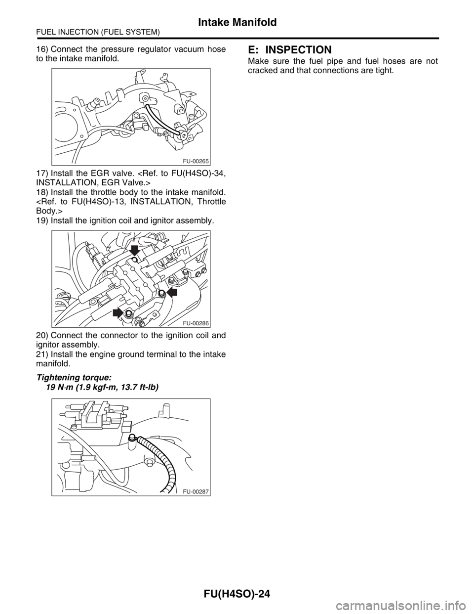
16) Connect the pressure regulator vacuum hose
to the intake manifold.
17) Install the EGR valve.
18) Install the throttle body to the intake manifold.
19) Install the ignition coil and ignitor assembly.
20) Connect the connector to the ignition coil and
ignitor assembly.
21) Install the engine ground terminal to the intake
manifold.
Tightening torque:
19 N
⋅m (1.9 kgf-m, 13.7 ft-lb)
E: INSPECTION
Make sure the fuel pipe and fuel hoses are not
cracked and that connections are tight.
FU-00265
FU-00286
FU-00287
Page 870 of 2870

MECHANICAL
ME(H4SO)
Page
1. General Description ....................................................................................2
2. Compression .............................................................................................25
3. Idle Speed .................................................................................................26
4. Ignition Timing ...........................................................................................27
5. Intake Manifold Vacuum............................................................................28
6. Engine Oil Pressure ..................................................................................29
7. Fuel Pressure ............................................................................................30
8. Valve Clearance ........................................................................................31
9. Engine Assembly ......................................................................................34
10. Engine Mounting .......................................................................................41
11. Preparation for Overhaul ...........................................................................42
12. V-belt .........................................................................................................43
13. Crank Pulley ..............................................................................................45
14. Timing Belt Cover......................................................................................47
15. Timing Belt ................................................................................................48
16. Cam Sprocket ...........................................................................................53
17. Crank Sprocket .........................................................................................55
18. Valve Rocker Assembly ............................................................................56
19. Camshaft ...................................................................................................58
20. Cylinder Head ...........................................................................................62
21. Cylinder Block ...........................................................................................69
22. Engine Trouble in General ........................................................................91
23. Engine Noise .............................................................................................96
Page 871 of 2870

ME(H4SO)-2
MECHANICAL
General Description
1. General Description
A: SPECIFICATION
NOTE:
STD: Standard I.D.: Inner Diameter O.D.: Outer Diameter US: Undersize OS: Oversize
EngineModel 2.0 L 2.5 L
Ty p eHorizontally opposed, liquid cooled, 4-cylinder, 4-stroke gaso-
line engine
Valve arrangement Belt driven, single over-head camshaft, 4-valve/cylinder
Bore×Stroke mm (in) 92×75 (3.62×2.95)99.5×79.0
(3.917×3.110)
Displacement
cm
3 (cu in)1,994 (121.67) 2,457 (150)
Compression ratio 10.0
Compression pressure
(at 200 — 300 rpm)kPa (kg/cm
2, psi)1,079 — 1,275 (11.0 — 13.0, 156 — 185)
Number of piston rings Pressure ring: 2, Oil ring: 1
Intake valve timingOpen 4° BTDC 1° BTDC
Close 48° ABDC 51° ABDC
Exhaust valve timingOpen 48° BBDC 50° BBDC
Close 4° AT D C 6° AT D C
Valve clearance Intake mm (in) 0.20±0.04 (0.0079±0.0016)
Exhaust mm (in) 0.25±0.04 (0.0098±0.0016)
Idling speed [at neutral position on
MT, or “P” or “N” range on AT]rpm650±100 (No load)
850±100 (A/C switch ON)
Firing order 1 → 3 → 2 → 4
Ignition timing BTDC/rpm 10°±10°/650
Belt
tensioner
adjusterProtrusion of adjuster rod mm (in) 5.7 — 6.7 (0.224 — 0.263)
Belt
tensionerSpacer O.D. mm (in) 17.955 — 17.975 (0.7069 — 0.7077)
Tensioner bush I.D. mm (in) 18.00 — 18.08 (0.7087 — 0.7118)
Clearance between spacer and bush mm (in)STD 0.025 — 0.125 (0.0010 — 0.0049)
Limit 0.175 (0.0069)
Side clearance of spacer mm (in)STD 0.20 — 0.55 (0.0079 — 0.0217)
Limit 0.81 (0.0319)
Valve rocker
armClearance between shaft and arm mm (in)STD 0.020 — 0.054 (0.0008 — 0.0021)
Limit 0.10 (0.0039)
CamshaftBend limit mm (in) 0.025 (0.0010)
Thrust clearance mm (in)STD 0.030 — 0.090 (0.0012 — 0.0035)
Limit 0.10 (0.0039)
Cam lobe height mm (in)2.0 LIntakeSTD 38.732 — 38.832 (1.5249 — 1.5288)
Limit 38.632 (1.5209)
ExhaustSTD 39.259 — 39.359 (1.5456 — 1.5496)
Limit 39.157 (1.5417)
2.5 LIntakeSTD 39.485 — 39.585 (1.5545 — 1.5585)
Limit 39.385 (1.5506)
ExhaustSTD 39.259 — 39.359 (1.5456 — 1.5496)
Limit 39.159 (1.5417)
Camshaft journal O.D. mm (in) 31.928 — 31.945 (1.2570 — 1.2577)
Camshaft journal hole I.D. (Cylinder head) mm (in) 32.000 — 32.018 (1.2598 — 1.2605)
Oil clearance mm (in)STD 0.055 — 0.090 (0.0022 — 0.0035)
Limit 0.10 (0.0039)
Page 879 of 2870
ME(H4SO)-10
MECHANICAL
General Description
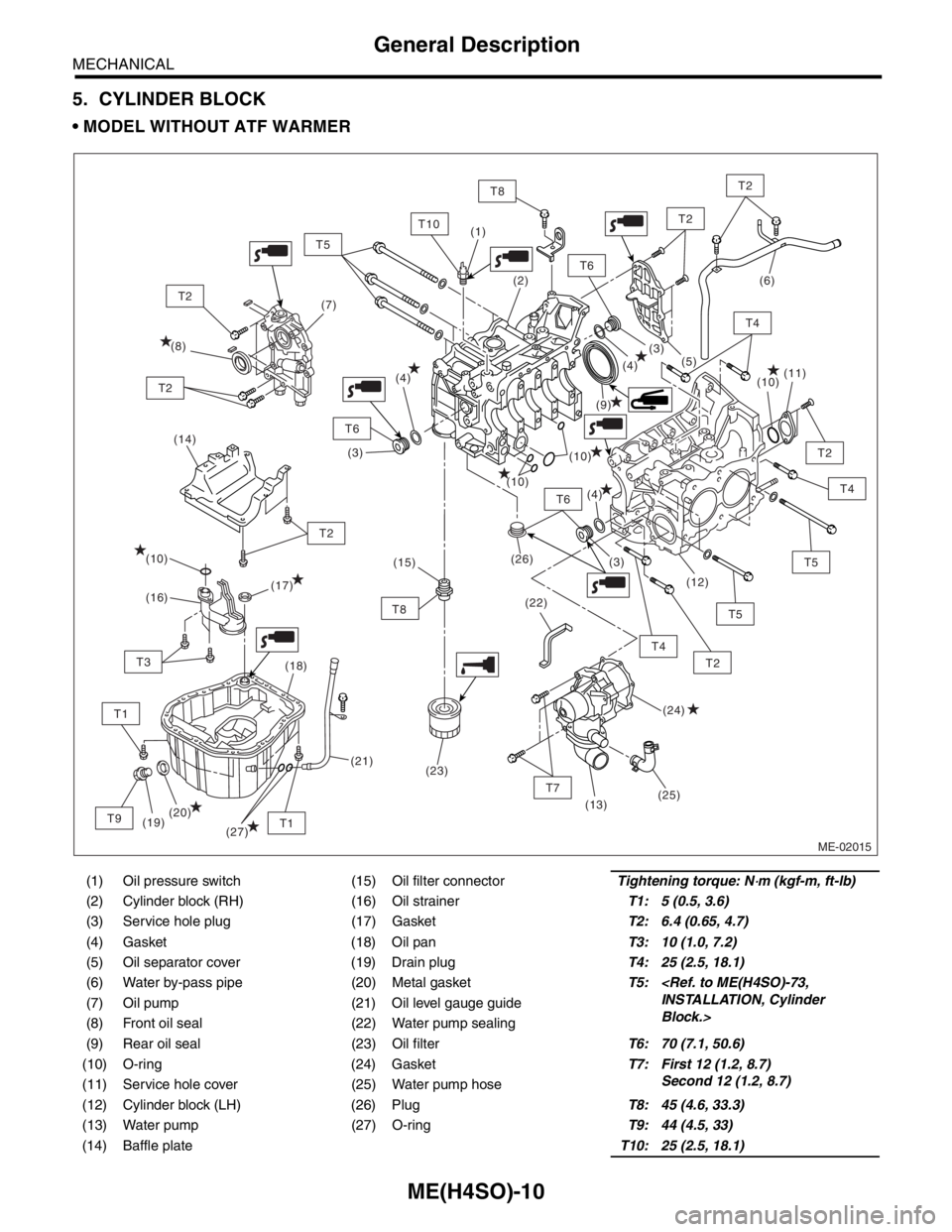
5. CYLINDER BLOCK
MODEL WITHOUT ATF WARMER
(1) Oil pressure switch (15) Oil filter connectorTightening torque: N⋅m (kgf-m, ft-lb)
(2) Cylinder block (RH) (16) Oil strainerT1: 5 (0.5, 3.6)
(3) Service hole plug (17) GasketT2: 6.4 (0.65, 4.7)
(4) Gasket (18) Oil panT3: 10 (1.0, 7.2)
(5) Oil separator cover (19) Drain plugT4: 25 (2.5, 18.1)
(6) Water by-pass pipe (20) Metal gasketT5:
Block.> (7) Oil pump (21) Oil level gauge guide
(8) Front oil seal (22) Water pump sealing
(9) Rear oil seal (23) Oil filterT6: 70 (7.1, 50.6)
(10) O-ring (24) GasketT7: First 12 (1.2, 8.7)
Second 12 (1.2, 8.7)
(11) Service hole cover (25) Water pump hose
(12) Cylinder block (LH) (26) PlugT8: 45 (4.6, 33.3)
(13) Water pump (27) O-ringT9: 44 (4.5, 33)
(14) Baffle plateT10: 25 (2.5, 18.1)
ME-02015
(14)
T6
T7
T2
T2
T4
T8
T4
T5
T2
T6
T6
T10
T1
T2
T8
T1
T3
T9
T2
T2
(9) (8)(7)(6)
(10)
(10)
(10)
(26)
(22)(11)
(12)
(13)
(19)(18)
(20)(17)
(16)
(24) (10)
(25)(5)
(4)
(4)
(4)(3)
(3)
(3) (2) (1)
(21)(15)
(23)
T5
T2
T5
T4
(27)
Page 880 of 2870
ME(H4SO)-11
MECHANICAL
General Description
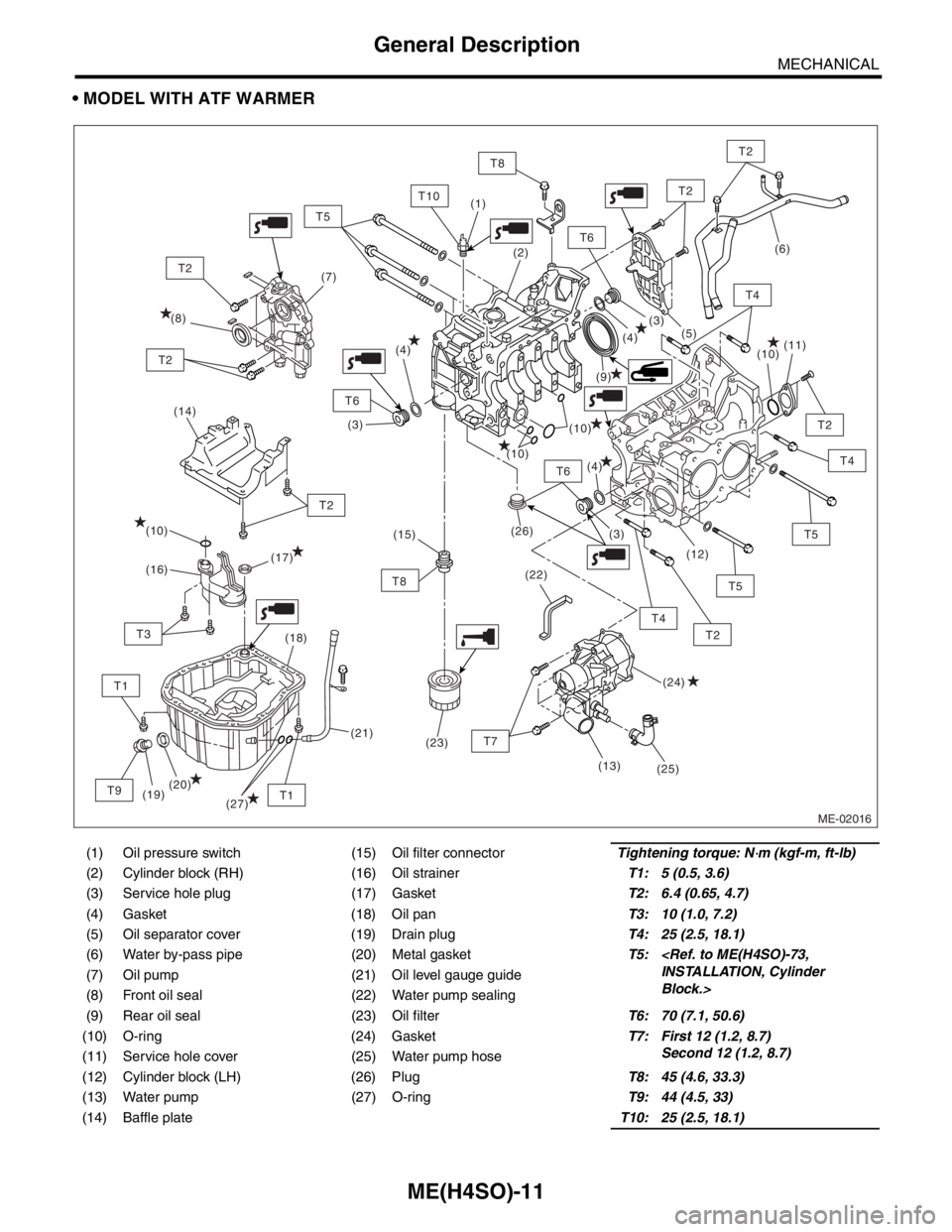
MODEL WITH ATF WARMER
(1) Oil pressure switch (15) Oil filter connectorTightening torque: N⋅m (kgf-m, ft-lb)
(2) Cylinder block (RH) (16) Oil strainerT1: 5 (0.5, 3.6)
(3) Service hole plug (17) GasketT2: 6.4 (0.65, 4.7)
(4) Gasket (18) Oil panT3: 10 (1.0, 7.2)
(5) Oil separator cover (19) Drain plugT4: 25 (2.5, 18.1)
(6) Water by-pass pipe (20) Metal gasketT5:
Block.> (7) Oil pump (21) Oil level gauge guide
(8) Front oil seal (22) Water pump sealing
(9) Rear oil seal (23) Oil filterT6: 70 (7.1, 50.6)
(10) O-ring (24) GasketT7: First 12 (1.2, 8.7)
Second 12 (1.2, 8.7)
(11) Service hole cover (25) Water pump hose
(12) Cylinder block (LH) (26) PlugT8: 45 (4.6, 33.3)
(13) Water pump (27) O-ringT9: 44 (4.5, 33)
(14) Baffle plateT10: 25 (2.5, 18.1)
ME-02016
(14)
T6
T2
T2
T4
T8
T5
T2
T6
T6
T10
T1
T2
T8
T1
T3
T9
T2
T2
(9) (8)(7)
(10)
(10)
(10)
(26)
(22)(11)
(12)
(19)(18)
(20)(17)
(16)
(24) (10)
(25)(5)
(4)
(4)
(4)(3)
(3)
(3) (2) (1)
(21)(15)
(23)
T5
T2
T5
T4
(27)
T7
(13)
(6)
T4
Page 898 of 2870
ME(H4SO)-29
MECHANICAL
Engine Oil Pressure
6. Engine Oil Pressure
A: INSPECTION
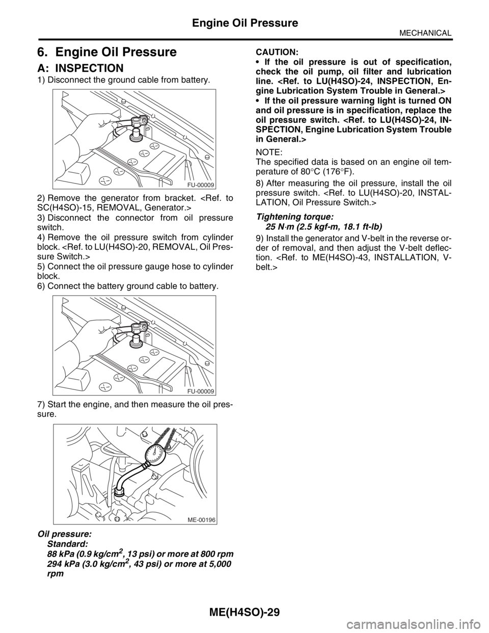
1) Disconnect the ground cable from battery.
2) Remove the generator from bracket.
3) Disconnect the connector from oil pressure
switch.
4) Remove the oil pressure switch from cylinder
block.
5) Connect the oil pressure gauge hose to cylinder
block.
6) Connect the battery ground cable to battery.
7) Start the engine, and then measure the oil pres-
sure.
Oil pressure:
Standard:
88 kPa (0.9 kg/cm
2, 13 psi) or more at 800 rpm
294 kPa (3.0 kg/cm2, 43 psi) or more at 5,000
rpmCAUTION:
If the oil pressure is out of specification,
check the oil pump, oil filter and lubrication
line.
If the oil pressure warning light is turned ON
and oil pressure is in specification, replace the
oil pressure switch.
in General.>
NOTE:
The specified data is based on an engine oil tem-
perature of 80°C (176°F).
8) After measuring the oil pressure, install the oil
pressure switch.
Tightening torque:
25 N
⋅m (2.5 kgf-m, 18.1 ft-lb)
9) Install the generator and V-belt in the reverse or-
der of removal, and then adjust the V-belt deflec-
tion.
FU-00009
FU-00009
ME-00196
Page 921 of 2870
ME(H4SO)-52
MECHANICAL
Timing Belt
2. AUTOMATIC BELT TENSION ADJUST-
ER
1) Visually check oil seals for leaks, and rod ends
for abnormal wear or scratches. If necessary, re-
place faulty parts.
2) Check that the adjuster rod does not move when
a pressure of 294 N (30 kgf, 66 lb) is applied to it.
This is to check adjuster rod stiffness.
3) If the adjuster rod is not stiff and moves freely
when applying 294 N (30 kgf, 66 lb), check it using
the following procedures:
(1) Slowly press the adjuster rod down to the
end surface of the cylinder. Repeat this motion 2
or 3 times.
(2) With the adjuster rod moved all the way up,
apply a pressure of 294 N (30 kgf, 66 lb) to it.
Check adjuster rod stiffness.
(3) If the adjuster rod is not stiff and moves
down, replace the automatic belt tension adjust-
er assembly with a new one.
CAUTION:
Always use a vertical type pressing tool to
move the adjuster rod down.
Do not use a lateral type vise.
Push the adjuster rod vertically.
Press-in the adjuster rod gradually taking
more than 3 minutes.
Do not allow press pressure to exceed 9,807
N (1,000 kgf, 2,205 lb).
Press the adjuster rod as far as the end sur-
face of the cylinder. Do not press the adjuster
rod into the cylinder. Doing so may damage the
cylinder.
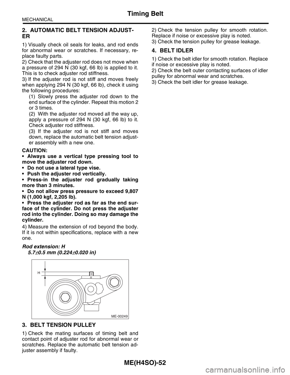
4) Measure the extension of rod beyond the body.
If it is not within specifications, replace with a new
one.
Rod extension: H
5.7
±0.5 mm (0.224±0.020 in)
3. BELT TENSION PULLEY
1) Check the mating surfaces of timing belt and
contact point of adjuster rod for abnormal wear or
scratches. Replace the automatic belt tension ad-
juster assembly if faulty.2) Check the tension pulley for smooth rotation.
Replace if noise or excessive play is noted.
3) Check the tension pulley for grease leakage.
4. BELT IDLER
1) Check the belt idler for smooth rotation. Replace
if noise or excessive play is noted.
2) Check the belt outer contacting surfaces of idler
pulley for abnormal wear and scratches.
3) Check the belt idler for grease leakage.
ME-00249
H
Page 923 of 2870

MECHANICAL
ME(H4SO)
Page
1. General Description ....................................................................................2
2. Compression .............................................................................................25
3. Idle Speed .................................................................................................26
4. Ignition Timing ...........................................................................................27
5. Intake Manifold Vacuum............................................................................28
6. Engine Oil Pressure ..................................................................................29
7. Fuel Pressure ............................................................................................30
8. Valve Clearance ........................................................................................31
9. Engine Assembly ......................................................................................34
10. Engine Mounting .......................................................................................41
11. Preparation for Overhaul ...........................................................................42
12. V-belt .........................................................................................................43
13. Crank Pulley ..............................................................................................45
14. Timing Belt Cover......................................................................................47
15. Timing Belt ................................................................................................48
16. Cam Sprocket ...........................................................................................53
17. Crank Sprocket .........................................................................................55
18. Valve Rocker Assembly ............................................................................56
19. Camshaft ...................................................................................................58
20. Cylinder Head ...........................................................................................62
21. Cylinder Block ...........................................................................................69
22. Engine Trouble in General ........................................................................91
23. Engine Noise .............................................................................................96