2004 SUBARU FORESTER oil pressure
[x] Cancel search: oil pressurePage 1462 of 2870

ME(H4DOTC)-6
MECHANICAL
General Description
2. 2.5 L MODEL
NOTE:
STD: Standard I.D.: Inner Diameter O.D.: Outer Diameter OS: Oversize US: Undersize
EngineModel2.5 L
Ty p eHorizontally opposed, liquid cooled, 4-cylinder,
4-stroke gasoline engine
Valve arrangement Belt driven, double overhead camshaft, 4-valve/cylinder
Bore×Stroke mm (in) 99.5×79.0 (3.92×3.11)
Piston displacement
cm
3 (cu in)2,457 (149.94)
Compression ratio 8.2
Compression pres-
sure (at 200 — 300
rpm)kPa (kgf/cm
2, psi)981 — 1,177 (10 — 12, 142 — 171)
Number of piston rings Pressure ring: 2, Oil ring: 1
Intake valve timingOpeningMax. retard ATDC 5°
Min. advance BTDC 15°
ClosingMax. retard ABDC 65°
Min. advance ABDC 45°
Exhaust valve timingOpening BBDC 55°
Closing ATDC 5°
Valve clearanceIntake mm (in) 0.20±0.02 (0.0079±0.0008)
Exhaust mm (in) 0.35±0.02 (0.0138±0.0008)
Idling speed
[At neutral position on MT, or “P” or “N”
range on AT]
rpmNo loadMT: 700±100
AT : 7 0 0±100
A/C ONA/C Refrigerant pressure
(LOW)MT: 725±100
AT : 7 5 0±100
A/C Refrigerant pressure
(HIGH)MT: 800±100
AT : 8 2 5±100
Firing order 1 → 3 → 2 → 4
Ignition timing BTDC/rpmMT model 17°±10°/700
AT model 17°±10°/700
Page 1473 of 2870

ME(H4DOTC)-17
MECHANICAL
General Description
(1) Oil pressure switch (15) AdapterTightening torque: N⋅m (kgf-m, ft-lb)
(2) Cylinder block (RH) (16) Oil coolerT1: 5 (0.5, 3.6)
(3) Service hole plug (17) Waster by-pass pipe T2: 6.4 (0.65, 4.7)
(4) Gasket (18) ConnectorT3: 10 (1.0, 7.2)
(5) Oil separator cover (19) Oil strainerT4: 25 (2.5, 18.1)
(6) Water by-pass pipe (20) GasketT5:
BLOCK.> (7) Oil pump (21) Oil pan
(8) Front oil seal (22) Drain plug
(9) Rear oil seal (23) Metal gasketT6: 70 (7.1, 50.6)
(10) O-ring (24) Oil level gauge guideT7: First 12 (1.2, 8.7)
Second 12 (1.2, 8.7)
(11) Service hole cover (25) Oil filter
(12) Cylinder block (LH) (26) GasketT8: 16 (1.6, 11.6)
(13) Water pump (27) Water pump hoseT9: 44 (4.5, 33)
(14) Baffle plate (28) PlugT10: 25 (2.5, 18.1)
T11: 54 (5.3, 39)
T12: 45 (4.6, 33)
Page 1491 of 2870

ME(H4DOTC)-35
MECHANICAL
Engine Oil Pressure
6. Engine Oil Pressure
A: INSPECTION
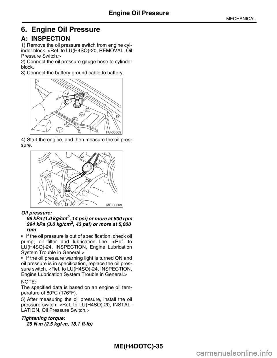
1) Remove the oil pressure switch from engine cyl-
inder block.
2) Connect the oil pressure gauge hose to cylinder
block.
3) Connect the battery ground cable to battery.
4) Start the engine, and then measure the oil pres-
sure.
Oil pressure:
98 kPa (1.0 kg/cm
2, 14 psi) or more at 800 rpm
294 kPa (3.0 kg/cm2, 43 psi) or more at 5,000
rpm
If the oil pressure is out of specification, check oil
pump, oil filter and lubrication line.
System Trouble in General.>
If the oil pressure warning light is turned ON and
oil pressure is in specification, replace the oil pres-
sure switch.
NOTE:
The specified data is based on an engine oil tem-
perature of 80°C (176°F).
5) After measuring the oil pressure, install the oil
pressure switch.
Tightening torque:
25 N
⋅m (2.5 kgf-m, 18.1 ft-lb)
FU-00009
ME-00009
Page 1498 of 2870

MECHANICAL
ME(H4DOTC)
Page
1. General Description ....................................................................................2
2. Compression .............................................................................................31
3. Idle Speed .................................................................................................32
4. Ignition Timing ...........................................................................................33
5. Intake Manifold Vacuum............................................................................34
6. Engine Oil Pressure ..................................................................................35
7. Fuel Pressure ............................................................................................36
8. Valve Clearance ........................................................................................37
9. Engine Assembly ......................................................................................41
10. Engine Mounting .......................................................................................50
11. Preparation for Overhaul ...........................................................................51
12. V-belt .........................................................................................................52
13. Crank Pulley ..............................................................................................55
14. Timing Belt Cover......................................................................................57
15. Timing Belt Assembly................................................................................58
16. Cam Sprocket ...........................................................................................67
17. Crank Sprocket .........................................................................................68
18. Camshaft ...................................................................................................69
19. Cylinder Head Assembly ...........................................................................76
20. Cylinder Block ...........................................................................................84
21. Intake and Exhaust Valve .......................................................................115
22. Piston ......................................................................................................116
23. Connecting Rod ......................................................................................117
24. Crankshaft ...............................................................................................118
25. Engine Trouble in General ......................................................................119
26. Engine Noise ...........................................................................................124
Page 1503 of 2870

ME(H4DOTC)-45
MECHANICAL
Engine Assembly
26) Support the transmission with a garage jack.
NOTE:
Before moving the engine away from transmission,
check to be sure no work has been overlooked. Do-
ing this is very important in order to facilitate re-in-
stallation and because transmission lowers under
its own weight.
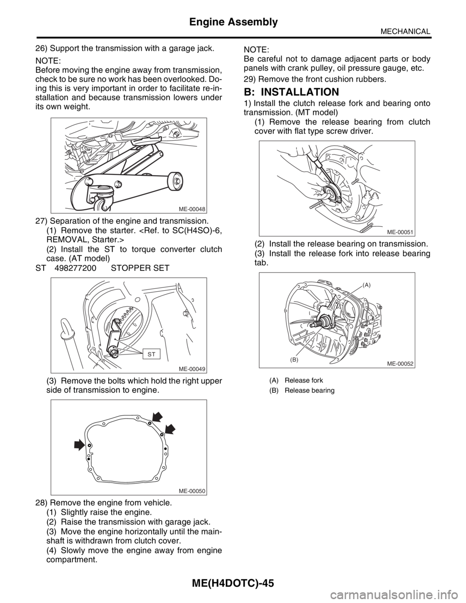
27) Separation of the engine and transmission.
(1) Remove the starter.
(2) Install the ST to torque converter clutch
case. (AT model)
ST 498277200 STOPPER SET
(3) Remove the bolts which hold the right upper
side of transmission to engine.
28) Remove the engine from vehicle.
(1) Slightly raise the engine.
(2) Raise the transmission with garage jack.
(3) Move the engine horizontally until the main-
shaft is withdrawn from clutch cover.
(4) Slowly move the engine away from engine
compartment.NOTE:
Be careful not to damage adjacent parts or body
panels with crank pulley, oil pressure gauge, etc.
29) Remove the front cushion rubbers.
B: INSTALLATION
1) Install the clutch release fork and bearing onto
transmission. (MT model)
(1) Remove the release bearing from clutch
cover with flat type screw driver.
(2) Install the release bearing on transmission.
(3) Install the release fork into release bearing
tab.
ME-00048
ST
ME-00049
ME-00050
(A) Release fork
(B) Release bearing
ME-00051
ME-00052
(A)
(B)
Page 1504 of 2870

ME(H4DOTC)-46
MECHANICAL
Engine Assembly
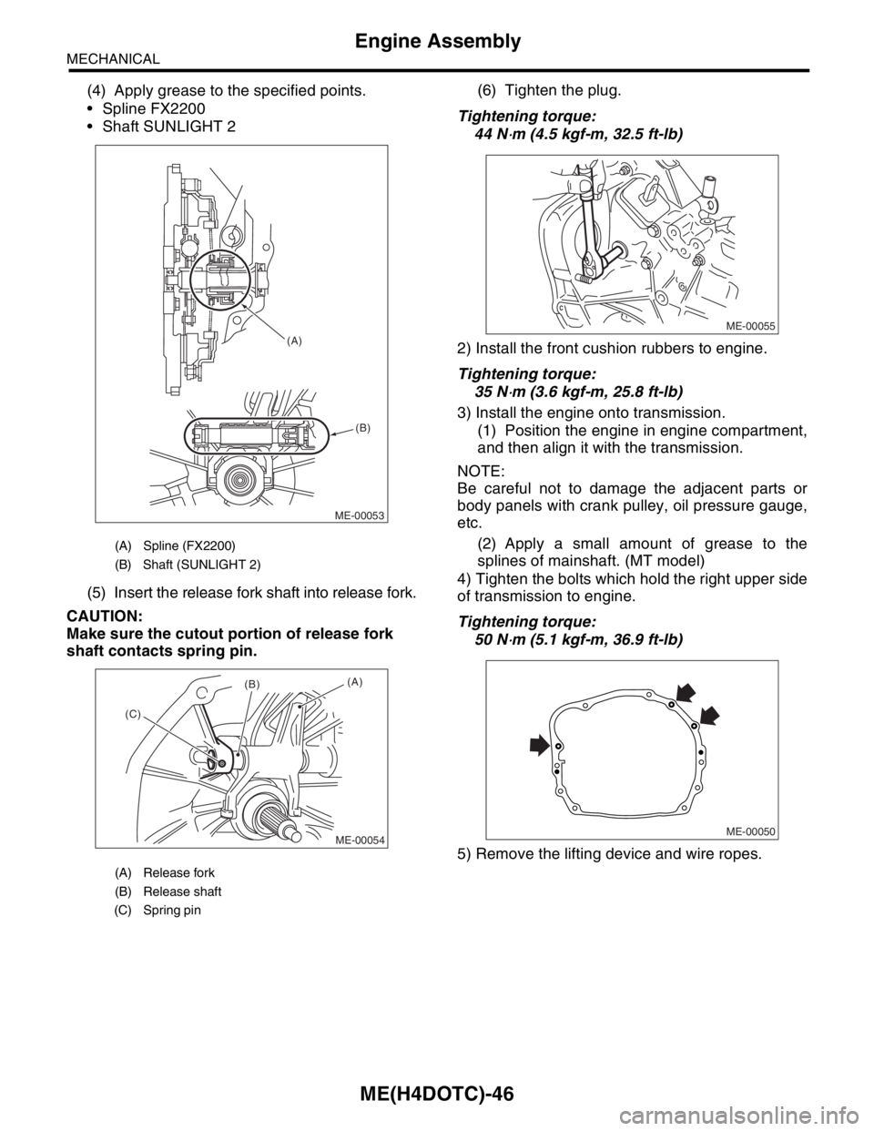
(4) Apply grease to the specified points.
Spline FX2200
Shaft SUNLIGHT 2
(5) Insert the release fork shaft into release fork.
CAUTION:
Make sure the cutout portion of release fork
shaft contacts spring pin.(6) Tighten the plug.
Tightening torque:
44 N
⋅m (4.5 kgf-m, 32.5 ft-lb)
2) Install the front cushion rubbers to engine.
Tightening torque:
35 N
⋅m (3.6 kgf-m, 25.8 ft-lb)
3) Install the engine onto transmission.
(1) Position the engine in engine compartment,
and then align it with the transmission.
NOTE:
Be careful not to damage the adjacent parts or
body panels with crank pulley, oil pressure gauge,
etc.
(2) Apply a small amount of grease to the
splines of mainshaft. (MT model)
4) Tighten the bolts which hold the right upper side
of transmission to engine.
Tightening torque:
50 N
⋅m (5.1 kgf-m, 36.9 ft-lb)
5) Remove the lifting device and wire ropes.
(A) Spline (FX2200)
(B) Shaft (SUNLIGHT 2)
(A) Release fork
(B) Release shaft
(C) Spring pin
ME-00053 (A)
(B)
ME-00054
(A)(B)
(C)ME-00055
ME-00050
Page 1518 of 2870

ME(H4DOTC)-60
MECHANICAL
Timing Belt Assembly
Do not release the press pressure until stopper
pin is completely inserted.
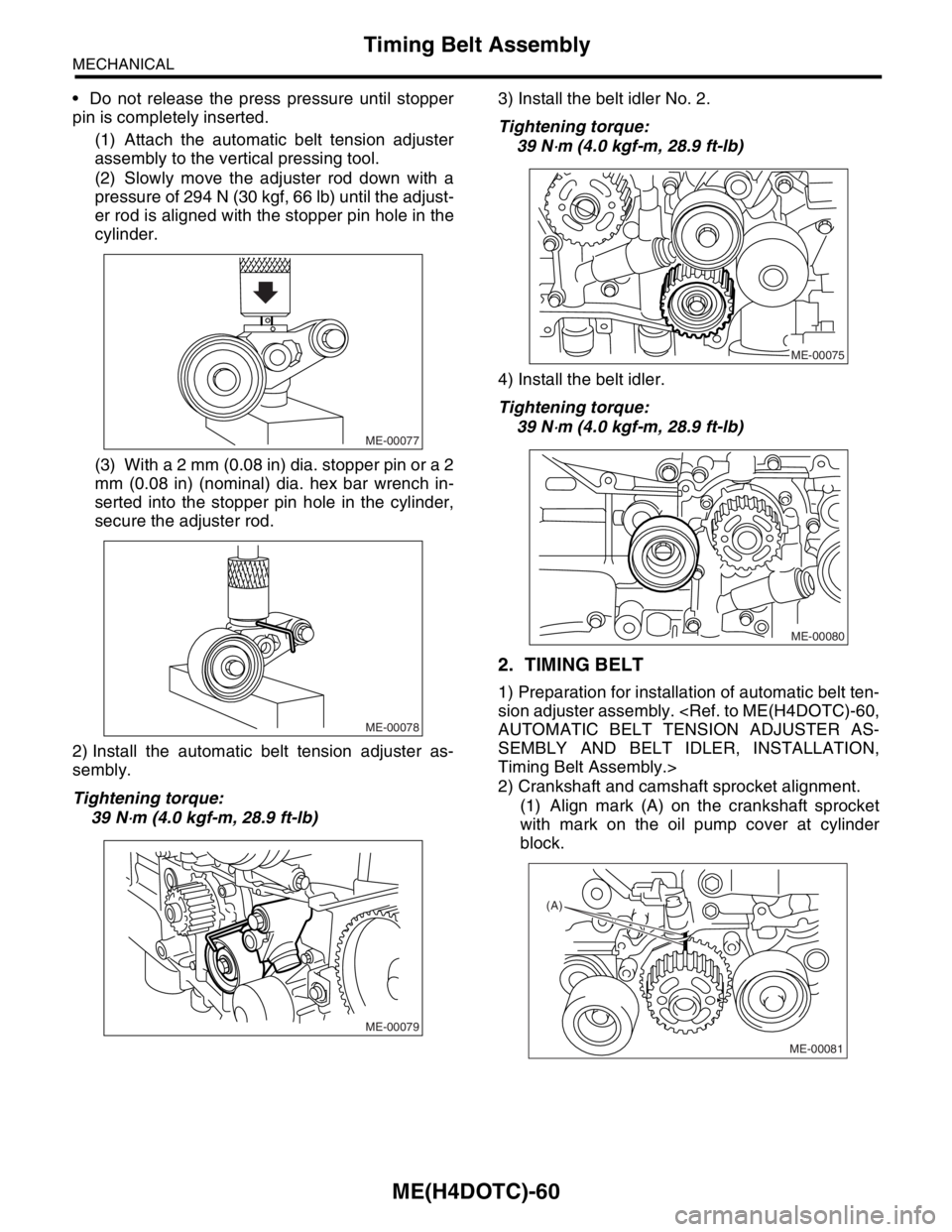
(1) Attach the automatic belt tension adjuster
assembly to the vertical pressing tool.
(2) Slowly move the adjuster rod down with a
pressure of 294 N (30 kgf, 66 lb) until the adjust-
er rod is aligned with the stopper pin hole in the
cylinder.
(3) With a 2 mm (0.08 in) dia. stopper pin or a 2
mm (0.08 in) (nominal) dia. hex bar wrench in-
serted into the stopper pin hole in the cylinder,
secure the adjuster rod.
2) Install the automatic belt tension adjuster as-
sembly.
Tightening torque:
39 N
⋅m (4.0 kgf-m, 28.9 ft-lb)3) Install the belt idler No. 2.
Tightening torque:
39 N
⋅m (4.0 kgf-m, 28.9 ft-lb)
4) Install the belt idler.
Tightening torque:
39 N
⋅m (4.0 kgf-m, 28.9 ft-lb)
2. TIMING BELT
1) Preparation for installation of automatic belt ten-
sion adjuster assembly.
SEMBLY AND BELT IDLER, INSTALLATION,
Timing Belt Assembly.>
2) Crankshaft and camshaft sprocket alignment.
(1) Align mark (A) on the crankshaft sprocket
with mark on the oil pump cover at cylinder
block.
ME-00077
ME-00078
ME-00079
ME-00075
ME-00080
(A)
ME-00081
Page 1523 of 2870

ME(H4DOTC)-65
MECHANICAL
Timing Belt Assembly
7) Install the timing belt cover.
Cover.>
8) Install the crank pulley.
9) Install the V-belt.
C: INSPECTION
1. TIMING BELT
1) Check the timing belt teeth for breaks, cracks,
and wear. If any fault is found, replace the belt.
2) Check the condition of back side of belt; if any
crack is found, replace the belt.
NOTE:
Be careful not to let oil, grease or coolant contact
the belt. Remove quickly and thoroughly if this hap-
pens.
Do not bend the belt sharply.
Bending radius: h
60 mm (2.36 in) or more
2. AUTOMATIC BELT TENSION ADJUST-
ER
1) Visually check the oil seals for leaks, and rod
ends for abnormal wear or scratches. If necessary,
replace the automatic belt tension adjuster assem-
bly.
NOTE:
Slight traces of oil at rod’s oil seal does not indicate
a problem.
2) Check that the adjuster rod does not move when
a pressure of 294 N (30 kgf, 66 lb) is applied to it.
This is to check adjuster rod stiffness.
3) If the adjuster rod is not stiff and moves freely
when applying 294 N (30 kgf, 66 lb), check it using
the following procedures:
(1) Slowly press the adjuster rod down to the
end surface of the cylinder. Repeat this motion 2
or 3 times.
(2) With the adjuster rod moved all the way up,
apply a pressure of 294 N (30 kgf, 66 lb) to it.
Check the adjuster rod stiffness.(3) If the adjuster rod is not stiff and moves
down, replace the automatic belt tension adjust-
er assembly with a new one.
NOTE:
Always use a vertical type pressing tool to move
the adjuster rod down.
Do not use a lateral type vise.
Push the adjuster rod vertically.
Press-in the push adjuster rod gradually taking
more than 3 minutes.
Do not allow press pressure to exceed 9,807 N
(1,000 kgf, 2,205 lb).
Press the adjuster rod as far as the end surface
of the cylinder. Do not press the adjuster rod into
the cylinder. Doing so may damage the cylinder.
4) Measure the extension of rod beyond the body.
If it is not within specifications, replace with a new
one.
Rod extension: H
6.2
±0.5 mm (0.244±0.020 in)
3. BELT TENSION PULLEY
1) Check the mating surfaces of timing belt and
contact point of adjuster rod for abnormal wear or
scratches. Replace the belt tension pulley if faulty.
2) Check the belt tension pulley for smooth rota-
tion. Replace if noise or excessive play is noted.
3) Check the belt tension pulley for grease leakage.
4. BELT IDLER
1) Check the belt idler for smooth rotation. Replace
if noise or excessive play is noted.
2) Check the outer contacting surfaces of idler pul-
ley for abnormal wear and scratches.
3) Check the belt idler for grease leakage.
ME-00099
h
ME-00100
H