Page 2350 of 2870

4AT-38
AUTOMATIC TRANSMISSION
Transfer Clutch Pressure Test
8. Transfer Clutch Pressure
Test
A: INSPECTION
Check the transfer clutch pressure in accordance
with the following steps in the same manner as with
line pressure.
Test.>
ST 498897700 OIL PRESSURE ADAPTER
SET
ST 498575400 OIL PRESSURE GAUGE
ASSYNOTE:
Before setting in FWD mode, install the spare fuse
on FWD mode switch.
NOTE:
If the oil pressure is not produced or if it does not
change in the AWD mode, the transfer duty sole-
noid or transfer valve assembly may be malfunc-
tioning. If the oil pressure is produced in the FWD
mode, the problem is similar to that in the AWD
mode.
STANDARD TRANSFER CLUTCH PRESSURE:
NON-TURBO MODEL
TURBO MODEL
(A) Test plug
AT-00021
(A)
Range posi-
tionON Duty
ratio (%)Acceleration opening angle (%)AWD m od e
Transfer clutch pressure
(kPa (kg/cm
2, psi))FWD mode
Transfer clutch pressure
(kPa (kg/cm2, psi))
D95100
(Fully opens)910 — 1,070
(9.3 — 10.9, 132 — 155)—
D60Adjust ON Duty ratio to 60%.
(Target 10%)410 — 490
(4.2 — 5.0, 59 — 71)—
N or P 50
(Fully closed)0—
D50
(Fully closed)—0
Range posi-
tionON Duty
ratio (%)Acceleration opening angle (%)AWD m od e
Transfer clutch pressure
(kPa (kg/cm
2, psi))FWD mode
Transfer clutch pressure
(kPa (kg/cm2, psi))
295100
(Fully opens)930 — 1,100
(9.5 — 11.2, 135 — 160)—
260Adjust ON Duty ratio to 60%.
(Target 12%)420 — 560
(4.3 — 5.7, 61 — 81)—
N or P 50
(Fully closed)0—
250
(Fully closed)—0
Page 2369 of 2870
4AT-56
AUTOMATIC TRANSMISSION
Front Vehicle Speed Sensor
17) Lower the transmission jack.
NOTE:
Do not separate the transmission jack and trans-
mission.
18) Remove the ATF cooler inlet and outlet pipes.
CAUTION:
When removing the outlet pipe, be careful not
to lose the ball and spring used with retaining
screw.
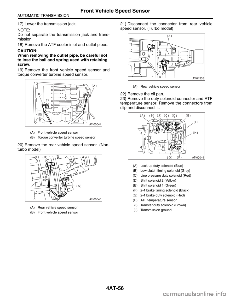
19) Remove the front vehicle speed sensor and
torque converter turbine speed sensor.
20) Remove the rear vehicle speed sensor. (Non-
turbo model)21) Disconnect the connector from rear vehicle
speed sensor. (Turbo model)
22) Remove the oil pan.
23) Remove the duty solenoid connector and ATF
temperature sensor. Remove the connectors from
clip and disconnect it.
(A) Front vehicle speed sensor
(B) Torque converter turbine speed sensor
(A) Rear vehicle speed sensor
(B) Front vehicle speed sensor
AT-00044
(A)
(B)
AT-00045
(A) (B)
(A) Rear vehicle speed sensor
(A) Lock-up duty solenoid (Blue)
(B) Low clutch timing solenoid (Gray)
(C) Line pressure duty solenoid (Red)
(D) Shift solenoid 2 (Yellow)
(E) Shift solenoid 1 (Green)
(F) 2-4 brake timing solenoid (Black)
(G) 2-4 brake duty solenoid (Red)
(H) ATF temperature sensor
(I) Transfer duty solenoid (Brown)
(J) Transmission ground
AT-01338
(A)
AT-00049
(A) (B) (J) (C) (D) (E)
(I)
(H)
(F) (G)
Page 2374 of 2870
4AT-61
AUTOMATIC TRANSMISSION
Control Valve Body
17.Control Valve Body
A: REMOVAL
1. NON-TURBO MODEL
1) Lift-up the vehicle.
2) Clean the transmission exterior.
3) Drain the ATF completely.
NOTE:
Tighten the drain plug (ATF) after draining the
ATF.
Always use new gasket.
Tightening torque:
25 N
⋅m (2.5 kgf-m, 18.1 ft-lb)
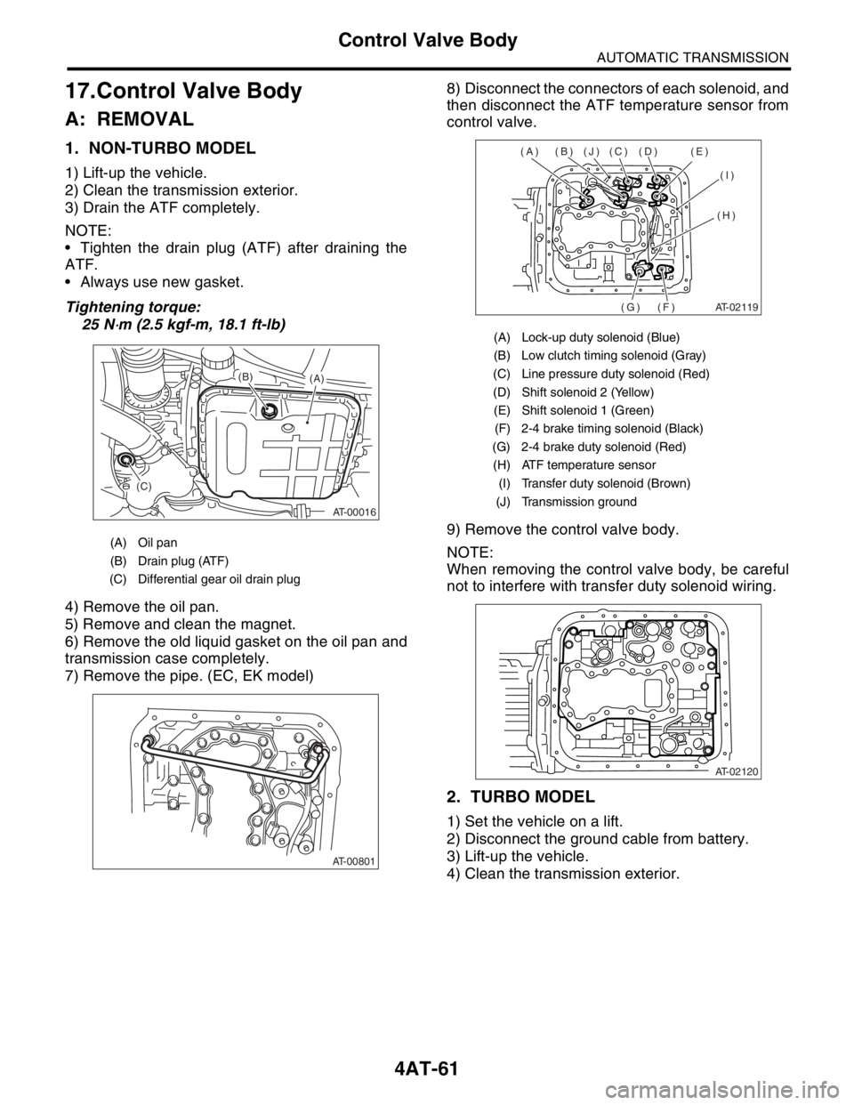
4) Remove the oil pan.
5) Remove and clean the magnet.
6) Remove the old liquid gasket on the oil pan and
transmission case completely.
7) Remove the pipe. (EC, EK model)8) Disconnect the connectors of each solenoid, and
then disconnect the ATF temperature sensor from
control valve.
9) Remove the control valve body.
NOTE:
When removing the control valve body, be careful
not to interfere with transfer duty solenoid wiring.
2. TURBO MODEL
1) Set the vehicle on a lift.
2) Disconnect the ground cable from battery.
3) Lift-up the vehicle.
4) Clean the transmission exterior.
(A) Oil pan
(B) Drain plug (ATF)
(C) Differential gear oil drain plug
AT-00016
(A) (B)
(C)
AT-00801
(A) Lock-up duty solenoid (Blue)
(B) Low clutch timing solenoid (Gray)
(C) Line pressure duty solenoid (Red)
(D) Shift solenoid 2 (Yellow)
(E) Shift solenoid 1 (Green)
(F) 2-4 brake timing solenoid (Black)
(G) 2-4 brake duty solenoid (Red)
(H) ATF temperature sensor
(I) Transfer duty solenoid (Brown)
(J) Transmission ground
AT-02119
(A) (B) (J) (C) (D) (E)
(I)
(H)
(F) (G)
AT-02120
Page 2376 of 2870
4AT-63
AUTOMATIC TRANSMISSION
Control Valve Body
B: INSTALLATION
1. NON-TURBO MODEL
1) Set the range select lever in “N” range.
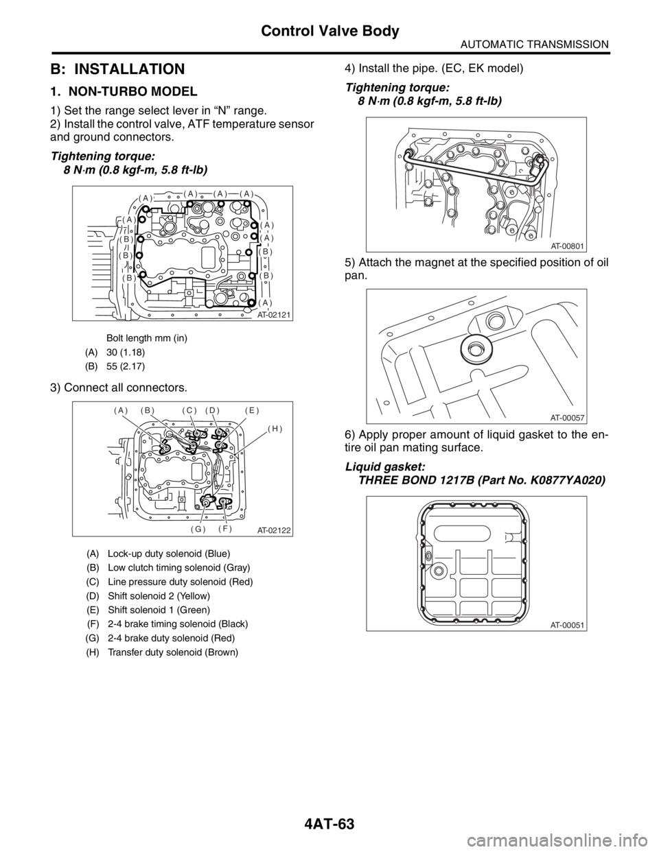
2) Install the control valve, ATF temperature sensor
and ground connectors.
Tightening torque:
8 N
⋅m (0.8 kgf-m, 5.8 ft-lb)
3) Connect all connectors.4) Install the pipe. (EC, EK model)
Tightening torque:
8 N
⋅m (0.8 kgf-m, 5.8 ft-lb)
5) Attach the magnet at the specified position of oil
pan.
6) Apply proper amount of liquid gasket to the en-
tire oil pan mating surface.
Liquid gasket:
THREE BOND 1217B (Part No. K0877YA020)
Bolt length mm (in)
(A) 30 (1.18)
(B) 55 (2.17)
(A) Lock-up duty solenoid (Blue)
(B) Low clutch timing solenoid (Gray)
(C) Line pressure duty solenoid (Red)
(D) Shift solenoid 2 (Yellow)
(E) Shift solenoid 1 (Green)
(F) 2-4 brake timing solenoid (Black)
(G) 2-4 brake duty solenoid (Red)
(H) Transfer duty solenoid (Brown)
AT-02121
(A)(A)(A)(A)
(A)(A)
(A)
(A)
(B)
(B)
(B)
(B)
(B)
AT-02122
(A) (B) (C) (D) (E)
(H)
(F)
(G)
AT-00801
AT-00057
AT-00051
Page 2378 of 2870
4AT-65
AUTOMATIC TRANSMISSION
Control Valve Body
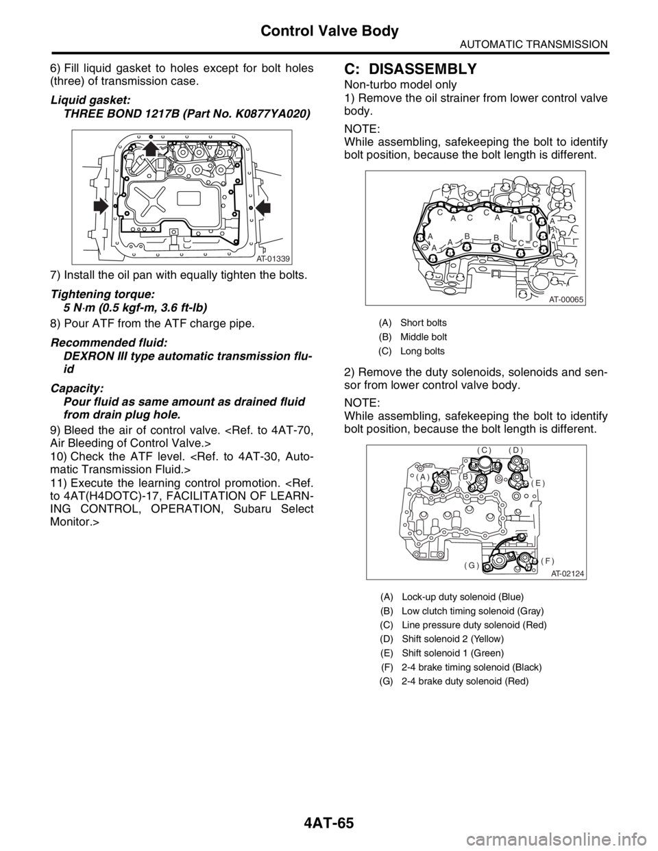
6) Fill liquid gasket to holes except for bolt holes
(three) of transmission case.
Liquid gasket:
THREE BOND 1217B (Part No. K0877YA020)
7) Install the oil pan with equally tighten the bolts.
Tightening torque:
5 N
⋅m (0.5 kgf-m, 3.6 ft-lb)
8) Pour ATF from the ATF charge pipe.
Recommended fluid:
DEXRON III type automatic transmission flu-
id
Capacity:
Pour fluid as same amount as drained fluid
from drain plug hole.
9) Bleed the air of control valve.
Air Bleeding of Control Valve.>
10) Check the ATF level.
matic Transmission Fluid.>
11) Execute the learning control promotion.
to 4AT(H4DOTC)-17, FACILITATION OF LEARN-
ING CONTROL, OPERATION, Subaru Select
Monitor.>
C: DISASSEMBLY
Non-turbo model only
1) Remove the oil strainer from lower control valve
body.
NOTE:
While assembling, safekeeping the bolt to identify
bolt position, because the bolt length is different.
2) Remove the duty solenoids, solenoids and sen-
sor from lower control valve body.
NOTE:
While assembling, safekeeping the bolt to identify
bolt position, because the bolt length is different.
AT-01339
(A) Short bolts
(B) Middle bolt
(C) Long bolts
(A) Lock-up duty solenoid (Blue)
(B) Low clutch timing solenoid (Gray)
(C) Line pressure duty solenoid (Red)
(D) Shift solenoid 2 (Yellow)
(E) Shift solenoid 1 (Green)
(F) 2-4 brake timing solenoid (Black)
(G) 2-4 brake duty solenoid (Red)
AT-00065
A
ABAA
AC
ACC
AB
AC
CC
AT-02124
(E)
(F)(G)
(D)(C)
(B)(A)
Page 2381 of 2870
4AT-68
AUTOMATIC TRANSMISSION
Control Valve Body
8) Install the lower separate plate to lower control
valve body.
9) Temporarily assemble the valve body.
NOTE:
Be careful not to drop the oil filter of lower control
valve body or steel balls in middle control valve
body and upper control valve body.
10) Tighten the bolt.NOTE:
Install the bolt (D) from upper control valve body
side.
Tightening torque:
8 N
⋅m (0.8 kgf-m, 5.8 ft-lb)
11) Insert solenoid and duty solenoid into the spec-
ified position.
(A) Lower separator plate
(B) Lower control valve body
AT-00076
(A)
(B)
AT-00077
Bolt length mm (in)
(A) 40 (1.57)
(B) 62 (2.44)
(C) 73 (2.87)
(D) 79 (3.11)
(A) Lock-up duty solenoid (Blue)
(B) Low clutch timing solenoid (Gray)
(C) Line pressure duty solenoid (Red)
(D) Shift solenoid 2 (Yellow)
(E) Shift solenoid 1 (Green)
(F) 2-4 brake timing solenoid (Black)
(G) 2-4 brake duty solenoid (Red)
AT-02125
B
B
BB D
C
B
D
AA
AA
AT-02124
(E)
(F)(G)
(D)(C)
(B)(A)
Page 2384 of 2870
4AT-71
AUTOMATIC TRANSMISSION
Shift Solenoids, Duty Solenoids and ATF Temperature Sensor
19.Shift Solenoids, Duty Sole-
noids and ATF Temperature
Sensor
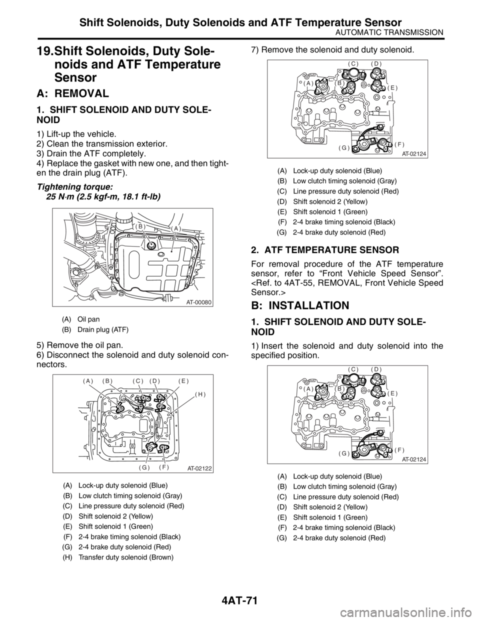
A: REMOVAL
1. SHIFT SOLENOID AND DUTY SOLE-
NOID
1) Lift-up the vehicle.
2) Clean the transmission exterior.
3) Drain the ATF completely.
4) Replace the gasket with new one, and then tight-
en the drain plug (ATF).
Tightening torque:
25 N
⋅m (2.5 kgf-m, 18.1 ft-lb)
5) Remove the oil pan.
6) Disconnect the solenoid and duty solenoid con-
nectors.7) Remove the solenoid and duty solenoid.
2. ATF TEMPERATURE SENSOR
For removal procedure of the ATF temperature
sensor, refer to “Front Vehicle Speed Sensor”.
Sensor.>
B: INSTALLATION
1. SHIFT SOLENOID AND DUTY SOLE-
NOID
1) Insert the solenoid and duty solenoid into the
specified position.
(A) Oil pan
(B) Drain plug (ATF)
(A) Lock-up duty solenoid (Blue)
(B) Low clutch timing solenoid (Gray)
(C) Line pressure duty solenoid (Red)
(D) Shift solenoid 2 (Yellow)
(E) Shift solenoid 1 (Green)
(F) 2-4 brake timing solenoid (Black)
(G) 2-4 brake duty solenoid (Red)
(H) Transfer duty solenoid (Brown)
AT-00080
(A)(B)
AT-02122
(A) (B) (C) (D) (E)
(H)
(F)
(G)
(A) Lock-up duty solenoid (Blue)
(B) Low clutch timing solenoid (Gray)
(C) Line pressure duty solenoid (Red)
(D) Shift solenoid 2 (Yellow)
(E) Shift solenoid 1 (Green)
(F) 2-4 brake timing solenoid (Black)
(G) 2-4 brake duty solenoid (Red)
(A) Lock-up duty solenoid (Blue)
(B) Low clutch timing solenoid (Gray)
(C) Line pressure duty solenoid (Red)
(D) Shift solenoid 2 (Yellow)
(E) Shift solenoid 1 (Green)
(F) 2-4 brake timing solenoid (Black)
(G) 2-4 brake duty solenoid (Red)
AT-02124
(E)
(F)(G)
(D)(C)
(B)(A)
AT-02124
(E)
(F)(G)
(D)(C)
(B)(A)
Page 2385 of 2870
4AT-72
AUTOMATIC TRANSMISSION
Shift Solenoids, Duty Solenoids and ATF Temperature Sensor
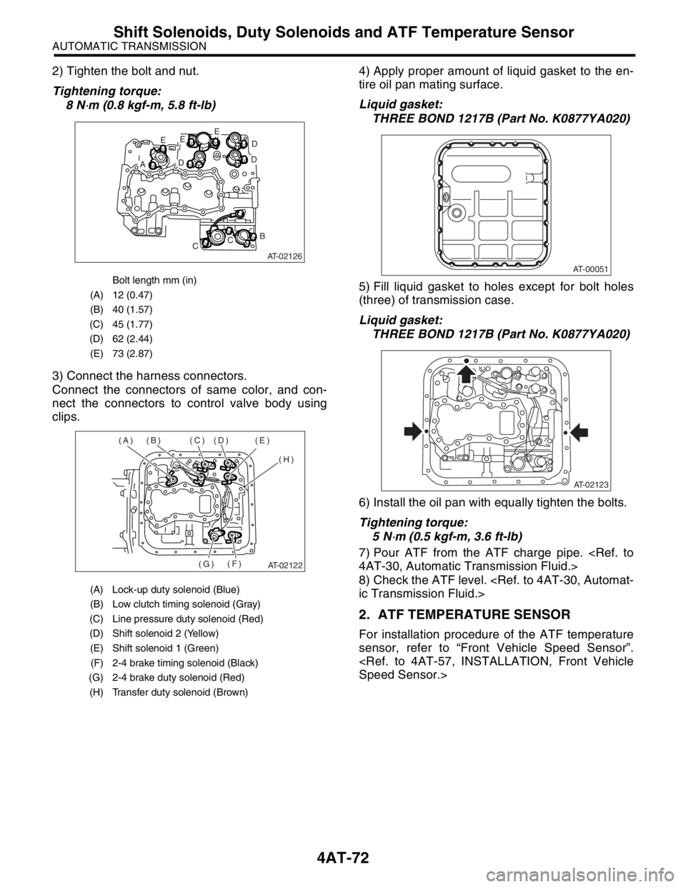
2) Tighten the bolt and nut.
Tightening torque:
8 N
⋅m (0.8 kgf-m, 5.8 ft-lb)
3) Connect the harness connectors.
Connect the connectors of same color, and con-
nect the connectors to control valve body using
clips.4) Apply proper amount of liquid gasket to the en-
tire oil pan mating surface.
Liquid gasket:
THREE BOND 1217B (Part No. K0877YA020)
5) Fill liquid gasket to holes except for bolt holes
(three) of transmission case.
Liquid gasket:
THREE BOND 1217B (Part No. K0877YA020)
6) Install the oil pan with equally tighten the bolts.
Tightening torque:
5 N
⋅m (0.5 kgf-m, 3.6 ft-lb)
7) Pour ATF from the ATF charge pipe.
4AT-30, Automatic Transmission Fluid.>
8) Check the ATF level.
ic Transmission Fluid.>
2. ATF TEMPERATURE SENSOR
For installation procedure of the ATF temperature
sensor, refer to “Front Vehicle Speed Sensor”.
Speed Sensor.>
Bolt length mm (in)
(A) 12 (0.47)
(B) 40 (1.57)
(C) 45 (1.77)
(D) 62 (2.44)
(E) 73 (2.87)
(A) Lock-up duty solenoid (Blue)
(B) Low clutch timing solenoid (Gray)
(C) Line pressure duty solenoid (Red)
(D) Shift solenoid 2 (Yellow)
(E) Shift solenoid 1 (Green)
(F) 2-4 brake timing solenoid (Black)
(G) 2-4 brake duty solenoid (Red)
(H) Transfer duty solenoid (Brown)
AT-02126
E
AD
EE
D
D
B
CC
AT-02122
(A) (B) (C) (D) (E)
(H)
(F)
(G)
AT-00051
AT-02123