2004 SUBARU FORESTER oil pressure
[x] Cancel search: oil pressurePage 2043 of 2870

EN(H4DOTC 2.5)-19
ENGINE (DIAGNOSTIC)
Engine Control Module (ECM) I/O Signal
Radiator fan relay 2 con-
trolB135 24ON: 0.5, or less
OFF: 10 — 13ON: 0.5, or less
OFF: 13 — 14Model with A/C only
Malfunction indicator
lightB134 17 — —Light “ON”: 1, or less
Light “OFF”: 10 — 14
Engine speed output B134 23 — 0 — 13, or more Waveform
Purge control solenoid
valveB134 14ON: 1, or less
OFF: 10 — 13ON: 1, or less
OFF: 13 — 14Wavefor m
Manifold
absolute
pressure
sensorSignal B136 22 1.7 — 2.4 1.1 — 1.6
— Pow er
supplyB136 16 5 5
GND
(sensors)B136 35 0 0
Small light switch B137 12ON: 0
OFF: 10 — 13ON: 0
OFF: 13 — 14—
Blower fan switch B137 13ON: 0
OFF: 10 — 13ON: 0
OFF: 13 — 14—
Rear defogger switch B137 11ON: 0
OFF: 10 — 13ON: 0
OFF: 13 — 14—
Power steering oil pres-
sure switchB137 10 10 — 13ON: 0
OFF: 13 — 14—
Front oxygen (A/F) sen-
sor signal (+)B134 33 2.8 — 3.2 2.8 — 3.2 —
Front oxygen (A/F) sen-
sor signal (−)B134 26 2.4 — 2.7 2.4 — 2.7 —
Front oxygen (A/F) sen-
sor shieldB134 25 0 0 —
SSM/GST communica-
tion lineB137 20 1 ← → 41 ← → 4—
GND (injector) B137 7 0 0 —
GND (ignition system) B135 12 0 0 —
GND (power supply)B135 4 0 0 —
B135 1 0 0 —
GND (control system)B137 1 0 0 —
B137 2 0 0 —
GND (Front oxygen (A/F)
sensor heater 1)B134 7 0 0 —
GND (Front oxygen (A/F)
sensor heater 2)B134 6 0 0 —
Camshaft position sen-
sor (LH)B135 8 0 — 0.9ON: 0
OFF: 4.7 — 5.3Wavefor m
Camshaft position sen-
sor (RH)B135 9 0 — 0.9ON: 0
OFF: 4.7 — 5.3Wavefor m
Fuel level sensor B136 20 0.12 — 4.75 0.12 — 4.75 —
Electronic
throttle
controlMain B136 180.64 — 0.72
Fully opens:
3.960.64 — 0.72
(After engine is
warmed-up.)Fully closed: 0.6 Fully opens:
3.96
Sub B136 291.51 — 1.58
Fully opens:
4.171.51 — 1.58
(After engine is
warmed-up)Fully closed: 1.48 Fully opens:
4.17
Pow er
supplyB136 16 5 5 —
GND
(sensor)B137 3 0 0 — DESCRIPTION Connector No. Terminal No.Signal (V)
NOTE
Ignition SW ON
(engine OFF)Engine ON
(Idling)
Page 2084 of 2870

EN(H4DOTC 2.5)-60
ENGINE (DIAGNOSTIC)
Diagnostics for Engine Starting Failure
Step Check Yes No
1 CHECK SPARK PLUG CONDITION.
1) Remove the spark plug.
2) Check the spark plug condition.
plug.
2 CHECK IGNITION SYSTEM FOR SPARKS.
1) Connect the spark plug to ignition coil.
2) Release the fuel pressure.
PRESSURE, OPERATION, Fuel.>
3) Contact the spark plug’s thread portion on
engine.
4) While opening the throttle valve fully, crank
the engine to check that spark occurs at each
cylinder.Does spark occur at each cyl-
inder?Check fuel pump
system.
62, FUEL PUMP
CIRCUIT, Diag-
nostics for Engine
Starting Failure.>Go to step 3.
3 CHECK POWER SUPPLY CIRCUIT FOR IG-
NITION COIL & IGNITOR ASSY.
1) Turn the ignition switch to OFF.
2) Disconnect the connector from ignition coil
& ignitor ASSY.
3) Turn the ignition switch to ON.
4) Measure the power supply voltage between
ignition coil & ignitor ASSY connector and
engine ground.
Connector & terminal
(E31) No. 3 (+) — Engine ground (
−):
(E32) No. 3 (+) — Engine ground (
−):
(E33) No. 3 (+) — Engine ground (
−):
(E34) No. 3 (+) — Engine ground (
−):Is the voltage more than 10 V? Go to step 4.Repair the harness
and connector.
N
OTE:
In this case repair
the following:
Open circuit in
harness between
ignition coil & igni-
tor ASSY, and igni-
tion switch
connector
Poor contact in
coupling connector
4 CHECK HARNESS OF IGNITION COIL & IG-
NITOR ASSY GROUND CIRCUIT.
1) Turn the ignition switch to OFF.
2) Measure the resistance between ignition
coil & ignitor ASSY connector and engine
ground.
Connector & terminal
(E31) No. 2 — Engine ground:
(E32) No. 2 — Engine ground:
(E33) No. 2 — Engine ground:
(E34) No. 2 — Engine ground:Is the resistance less than 5
Ω?Go to step 5.Repair the harness
and connector.
N
OTE:
In this case repair
the following:
Open circuit in
harness between
ignition coil & igni-
tor ASSY connec-
tor and engine
ground terminal
5 CHECK HARNESS BETWEEN ECM AND IG-
NITION COIL & IGNITOR ASSY CONNEC-
TOR.
1) Turn the ignition switch to OFF.
2) Disconnect the connector from ECM.
3) Disconnect the connector from ignition coil
& ignitor ASSY.
4) Measure the resistance of harness
between ECM and ignition coil & ignitor ASSY
connector.
Connector & terminal
(B135) No. 15 — (E34) No. 1:
(B135) No. 16 — (E33) No. 1:
(B135) No. 17 — (E32) No. 1:
(B135) No. 18 — (E31) No. 1:Is the resistance less than 1
Ω?Go to step 6.Repair the harness
and connector.
N
OTE:
In this case repair
the following:
OPEN CIR-
CUIT IN HAR-
NESS BETWEEN
ECM AND IGNI-
TION COIL &
IGNITOR ASSY
CONNECTOR.
Poor contact in
coupling connector
Page 2283 of 2870

EN(H4DOTC 2.5)-259
ENGINE (DIAGNOSTIC)
General Diagnostic Table
*1: Check ignition coil & ignitor ASSY and spark plug.
*2: Indicate the symptom occurring only in cold temperatures.
*3: Ensure the secure installation.
*4: Check fuel injector, fuel pressure regulator and fuel filter.
*5: Inspect air leak in air intake system. 7. Spark knock1) Manifold absolute pressure sensor
2) Mass air flow and intake air temperature sensor
3) Engine coolant temperature sensor
4) Knock sensor
5) Fuel injection parts (*4)
6) Fuel pump and fuel pump relay
8. After burning in exhaust system1) Manifold absolute pressure sensor
2) Mass air flow and intake air temperature sensor
3) Engine coolant temperature sensor (*2)
4) Fuel injection parts (*4)
5) Fuel pump and fuel pump relay Symptom Problem parts
Page 2313 of 2870

AUTOMATIC TRANSMISSION
4AT
Page
1. General Description ....................................................................................2
2. Automatic Transmission Fluid ...................................................................30
3. Differential Gear Oil...................................................................................31
4. Road Test..................................................................................................32
5. Stall Test ...................................................................................................33
6. Time Lag Test ...........................................................................................35
7. Line Pressure Test ....................................................................................36
8. Transfer Clutch Pressure Test ..................................................................38
9. Automatic Transmission Assembly ...........................................................39
10. Transmission Mounting System ................................................................47
11. Extension Case Oil Seal ...........................................................................49
12. Differential Side Retainer Oil Seal.............................................................50
13. Inhibitor Switch ..........................................................................................51
14. Front Vehicle Speed Sensor .....................................................................55
15. Rear Vehicle Speed Sensor ......................................................................59
16. Torque Converter Turbine Speed Sensor .................................................60
17. Control Valve Body ...................................................................................61
18. Air Bleeding of Control Valve ....................................................................70
19.
Shift Solenoids, Duty Solenoids and ATF Temperature Sensor.........................71
20. Transfer Duty Solenoid and Valve Body ...................................................73
21. ATF Filter ..................................................................................................76
22. Transmission Control Module (TCM) ........................................................77
23. Dropping Resistor .....................................................................................78
24. ATF Cooler Pipe and Hose .......................................................................79
25. ATF Cooler (With Warmer Function).........................................................84
26. Air Breather Hose......................................................................................87
27. Oil Charger Pipe........................................................................................88
28. Torque Converter Clutch Assembly ..........................................................89
29. Extension Case .........................................................................................90
30. Transfer Clutch..........................................................................................92
31. Reduction Driven Gear..............................................................................97
32. Reduction Drive Gear................................................................................99
33. Parking Pawl ...........................................................................................101
34. Torque Converter Clutch Case ...............................................................102
35. Oil Pump Housing ...................................................................................105
36. Drive Pinion Shaft Assembly ...................................................................111
37. Front Differential......................................................................................117
38. AT Main Case .........................................................................................123
39. Transmission Control Device ..................................................................142
Page 2321 of 2870

4AT-9
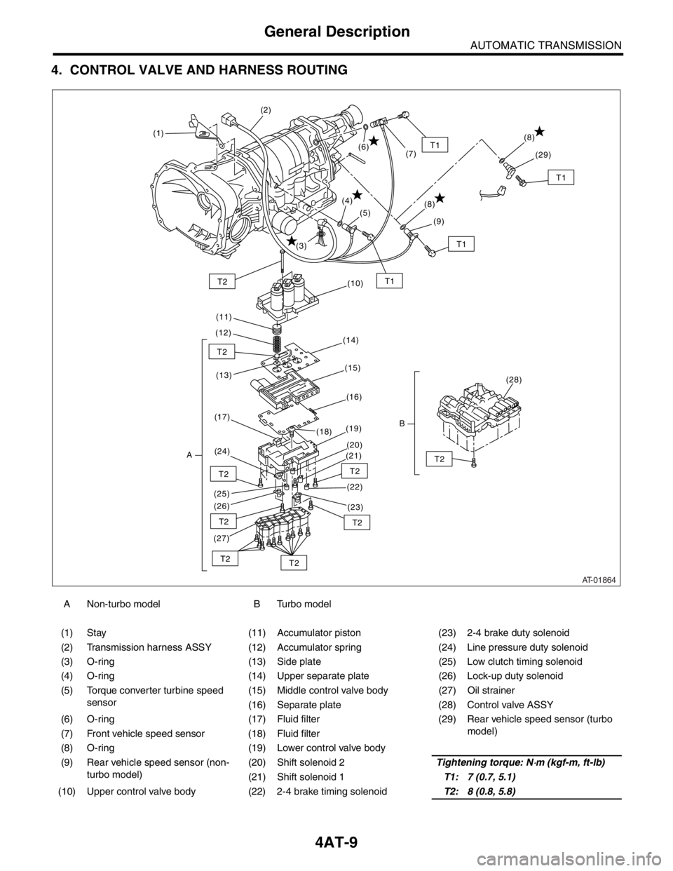
AUTOMATIC TRANSMISSION
General Description
4. CONTROL VALVE AND HARNESS ROUTING
A Non-turbo model B Turbo model
(1) Stay (11) Accumulator piston (23) 2-4 brake duty solenoid
(2) Transmission harness ASSY (12) Accumulator spring (24) Line pressure duty solenoid
(3) O-ring (13) Side plate (25) Low clutch timing solenoid
(4) O-ring (14) Upper separate plate (26) Lock-up duty solenoid
(5) Torque converter turbine speed
sensor(15) Middle control valve body (27) Oil strainer
(16) Separate plate (28) Control valve ASSY
(6) O-ring (17) Fluid filter (29) Rear vehicle speed sensor (turbo
model)
(7) Front vehicle speed sensor (18) Fluid filter
(8) O-ring (19) Lower control valve body
(9) Rear vehicle speed sensor (non-
turbo model)(20) Shift solenoid 2Tightening torque: N
⋅m (kgf-m, ft-lb)
(21) Shift solenoid 1T1: 7 (0.7, 5.1)
(10) Upper control valve body (22) 2-4 brake timing solenoidT2: 8 (0.8, 5.8)
AT-01864
T1T2
T2
T2
T2
T2
T2
T2T2
T2
T1
(1)(2)
(3)(4)
(5)
(6)
(7)
(10)
(11)
(12)
(14)
(13)(15)
(16)
(17)
A(24)(19)
(18)
(20)
(21)
(22)
(23) (26) (25)
(27)
(28)
B
T1
(8)
(9)
T1
(8)
(29)
Page 2327 of 2870

4AT-15
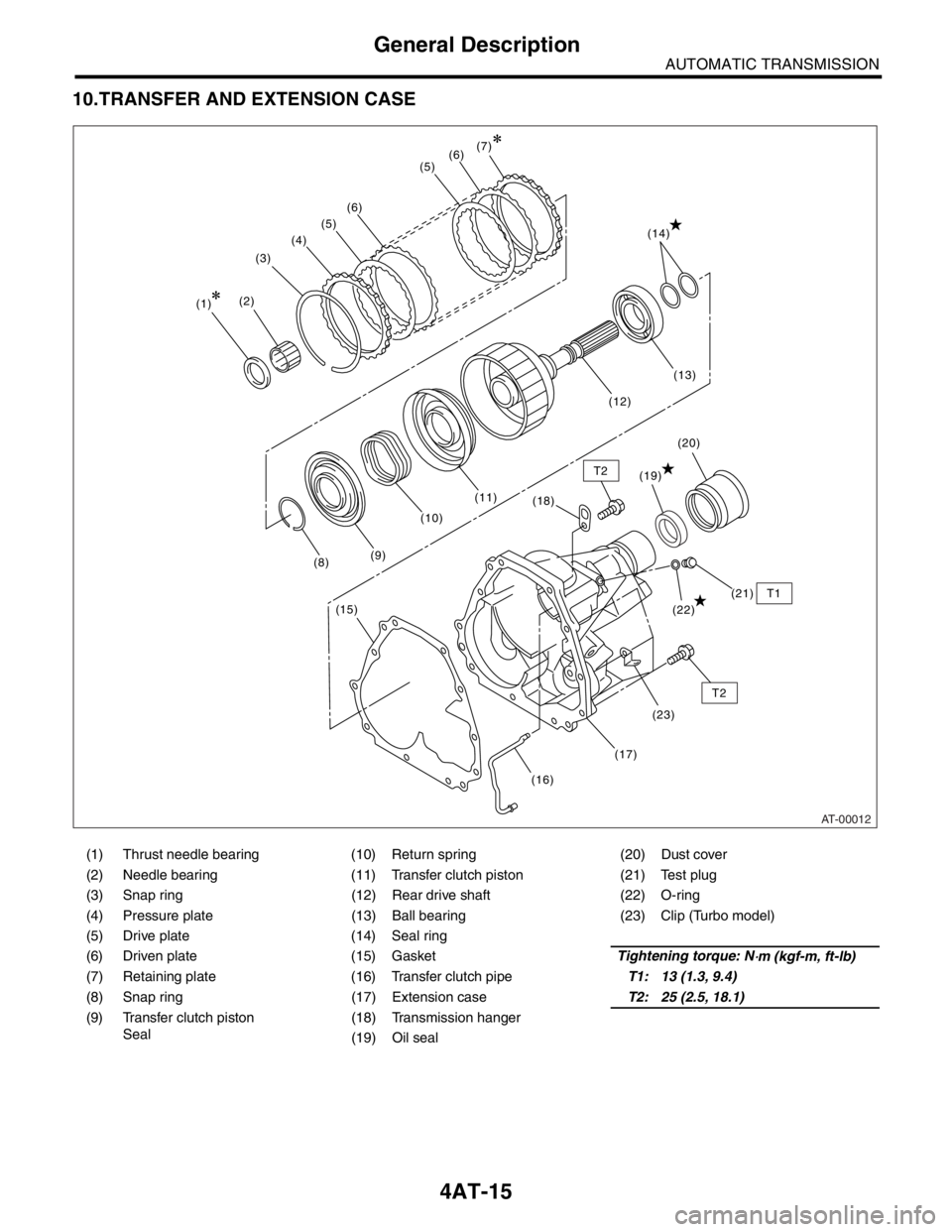
AUTOMATIC TRANSMISSION
General Description
10.TRANSFER AND EXTENSION CASE
(1) Thrust needle bearing (10) Return spring (20) Dust cover
(2) Needle bearing (11) Transfer clutch piston (21) Test plug
(3) Snap ring (12) Rear drive shaft (22) O-ring
(4) Pressure plate (13) Ball bearing (23) Clip (Turbo model)
(5) Drive plate (14) Seal ring
(6) Driven plate (15) GasketTightening torque: N
⋅m (kgf-m, ft-lb)
(7) Retaining plate (16) Transfer clutch pipeT1: 13 (1.3, 9.4)
(8) Snap ring (17) Extension caseT2: 25 (2.5, 18.1)
(9) Transfer clutch piston
Seal(18) Transmission hanger
(19) Oil seal
AT-00012
(1)(2)(3)(4)(5)(6)(7)
(8)(9)(10)(11)
(16)(23) (18)(19)
(22)(21) (12)(13) (14)
(15)
(5)
(17)
(20)
T2
T2
T1
(6)
Page 2331 of 2870

4AT-19
AUTOMATIC TRANSMISSION
General Description
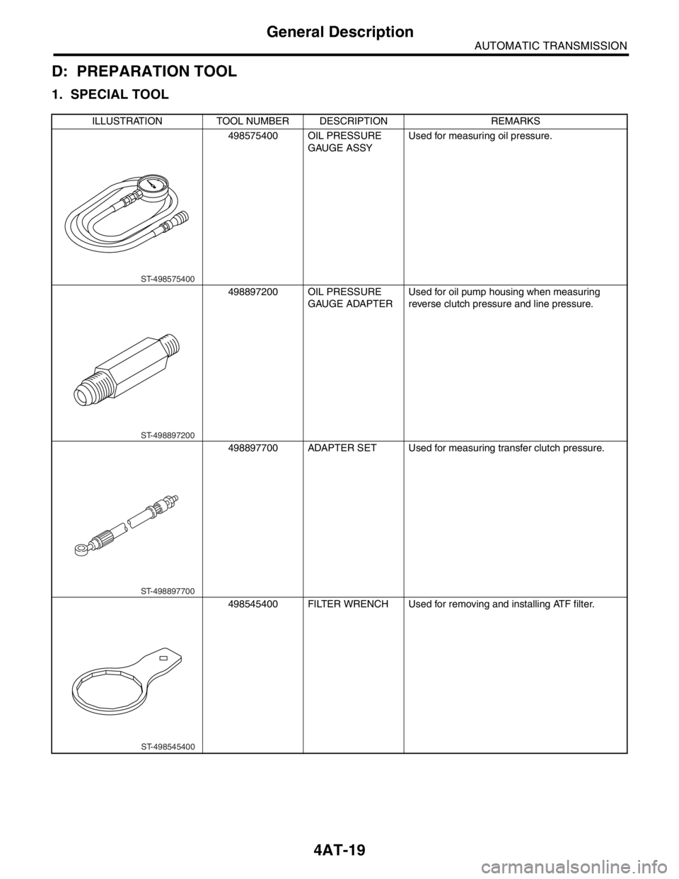
D: PREPARATION TOOL
1. SPECIAL TOOL
ILLUSTRATION TOOL NUMBER DESCRIPTION REMARKS
498575400 OIL PRESSURE
GAUGE ASSYUsed for measuring oil pressure.
498897200 OIL PRESSURE
GAUGE ADAPTERUsed for oil pump housing when measuring
reverse clutch pressure and line pressure.
498897700 ADAPTER SET Used for measuring transfer clutch pressure.
498545400 FILTER WRENCH Used for removing and installing ATF filter.
ST-498575400
ST-498897200
ST-498897700
ST-498545400
Page 2348 of 2870

4AT-36
AUTOMATIC TRANSMISSION
Line Pressure Test
7. Line Pressure Test
A: MEASUREMENT
NOTE:
If the clutch or the brake shows a sign of slippage or
shifting sensation is not correct, the line pressure
should be checked.
Excessive shocks during upshifting or shifting
takes place at a higher point than under normal cir-
cumstances, may be due to the line pressure being
too high.
Slippage or inability to operate the vehicle may,
in most cases, be due to insufficient oil pressure for
the operation of the clutch, brake or control valve.
1) Line pressure measurement (under no load):
(1) Before measuring line pressure, jack-up all
wheels.
(2) Maintain the temperature of ATF at approx.
70 — 80°C (158 — 176°F) during measurement.
(ATF will reach the above temperature after
idling the engine for approx. 30 minutes with the
select lever in “N” or “P”.)
2) Line pressure measurement (under heavy load):
(1) Before measuring line pressure, apply both
foot and parking brakes with all wheels chocked
(Same as for “stall” test conditions).
(2) Measure the line pressure when the select
lever is in “D”, “2” (HOLD switch ON) with engine
under stall conditions.
(3) Measure the line pressure within 5 seconds
after shifting the select lever to each position. (If
the line pressure needs to be measured again,
allow the engine to idle and cool it down more
than 1 minute.)
(4) Maintain the ATF temperature at approx. 70
— 80°C (158 — 176°F) during measurement.
(ATF will reach the above temperature after
idling the engine for approx. 30 minutes with the
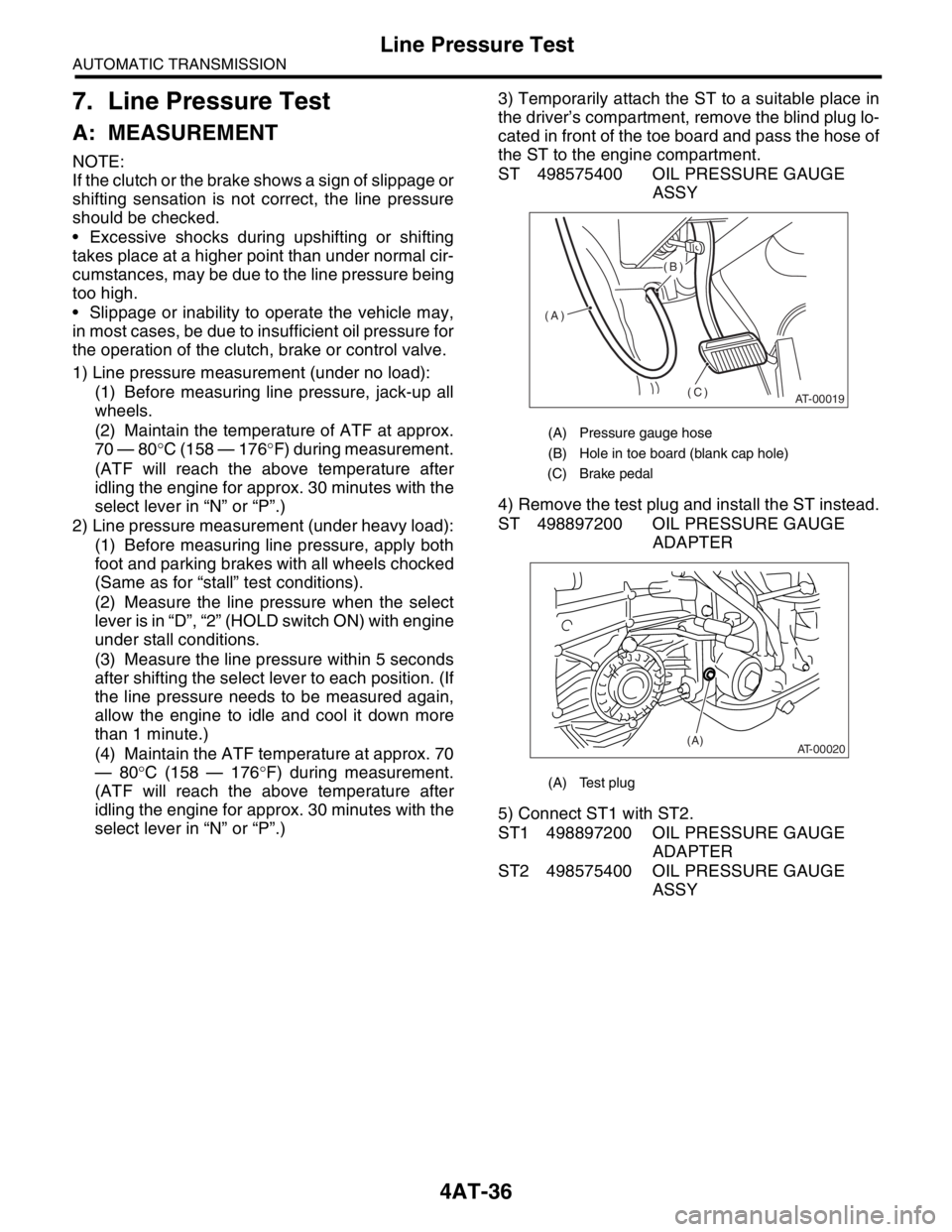
select lever in “N” or “P”.)3) Temporarily attach the ST to a suitable place in
the driver’s compartment, remove the blind plug lo-
cated in front of the toe board and pass the hose of
the ST to the engine compartment.
ST 498575400 OIL PRESSURE GAUGE
ASSY
4) Remove the test plug and install the ST instead.
ST 498897200 OIL PRESSURE GAUGE
ADAPTER
5) Connect ST1 with ST2.
ST1 498897200 OIL PRESSURE GAUGE
ADAPTER
ST2 498575400 OIL PRESSURE GAUGE
ASSY
(A) Pressure gauge hose
(B) Hole in toe board (blank cap hole)
(C) Brake pedal
(A) Test plug
AT-00019
(A)(B)
(C)
AT-00020(A)