2004 SUBARU FORESTER oil pressure
[x] Cancel search: oil pressurePage 501 of 2870
EI-25
EXTERIOR/INTERIOR TRIM
Front Bumper
C: REPAIR
1. COATING METHOD FOR PP BUMPER
Pro-
cess
No.Process name Job contents
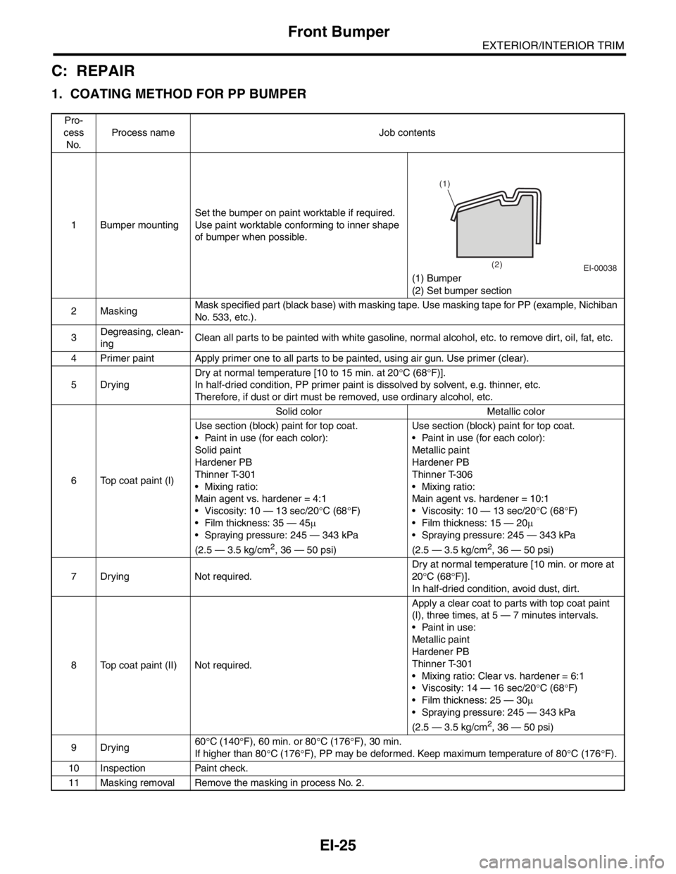
1 Bumper mountingSet the bumper on paint worktable if required.
Use paint worktable conforming to inner shape
of bumper when possible.
(1) Bumper
(2) Set bumper section
2MaskingMask specified part (black base) with masking tape. Use masking tape for PP (example, Nichiban
No. 533, etc.).
3Degreasing, clean-
ingClean all parts to be painted with white gasoline, normal alcohol, etc. to remove dirt, oil, fat, etc.
4 Primer paint Apply primer one to all parts to be painted, using air gun. Use primer (clear).
5DryingDry at normal temperature [10 to 15 min. at 20°C (68°F)].
In half-dried condition, PP primer paint is dissolved by solvent, e.g. thinner, etc.
Therefore, if dust or dirt must be removed, use ordinary alcohol, etc.
6 Top coat paint (I)Solid color Metallic color
Use section (block) paint for top coat.
Paint in use (for each color):
Solid paint
Hardener PB
Thinner T-301
Mixing ratio:
Main agent vs. hardener = 4:1
Viscosity: 10 — 13 sec/20°C (68°F)
Film thickness: 35 — 45µ
Spraying pressure: 245 — 343 kPa
(2.5 — 3.5 kg/cm
2, 36 — 50 psi)Use section (block) paint for top coat.
Paint in use (for each color):
Metallic paint
Hardener PB
Thinner T-306
Mixing ratio:
Main agent vs. hardener = 10:1
Viscosity: 10 — 13 sec/20°C (68°F)
Film thickness: 15 — 20µ
Spraying pressure: 245 — 343 kPa
(2.5 — 3.5 kg/cm2, 36 — 50 psi)
7 Drying Not required.Dry at normal temperature [10 min. or more at
20°C (68°F)].
In half-dried condition, avoid dust, dirt.
8 Top coat paint (II) Not required.Apply a clear coat to parts with top coat paint
(I), three times, at 5 — 7 minutes intervals.
Paint in use:
Metallic paint
Hardener PB
Thinner T-301
Mixing ratio: Clear vs. hardener = 6:1
Viscosity: 14 — 16 sec/20°C (68°F)
Film thickness: 25 — 30µ
Spraying pressure: 245 — 343 kPa
(2.5 — 3.5 kg/cm
2, 36 — 50 psi)
9Drying60°C (140°F), 60 min. or 80°C (176°F), 30 min.
If higher than 80°C (176°F), PP may be deformed. Keep maximum temperature of 80°C (176°F).
10 Inspection Paint check.
11 Masking removal Remove the masking in process No. 2.
EI-00038
(1)
(2)
Page 549 of 2870
EB-19
EXTERIOR BODY PANEL
Rear Gate Panel
C: DISPOSAL
1. REAR GATE DAMPER STAY
CAUTION:
Gas is colorless, odorless and harmless. How-
ever, gas pressure may spray cutting powder or
oil. Be sure to wear dust-resistant goggles.
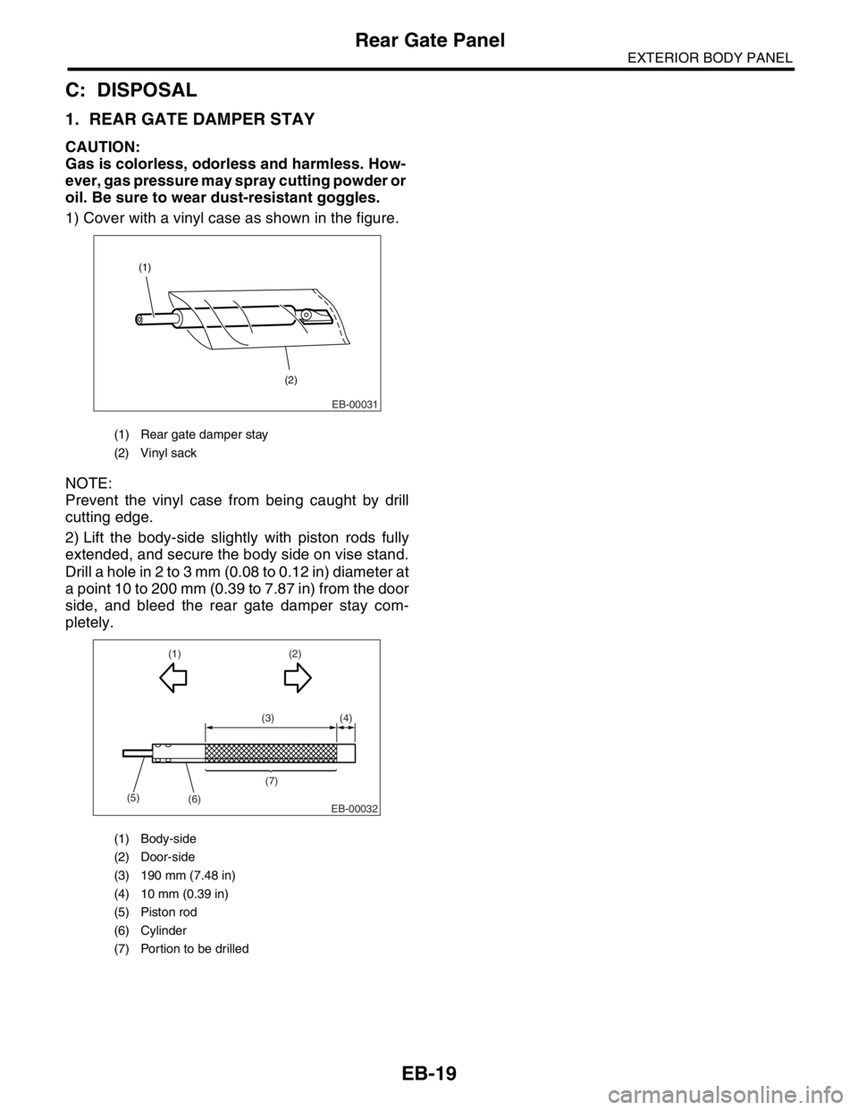
1) Cover with a vinyl case as shown in the figure.
NOTE:
Prevent the vinyl case from being caught by drill
cutting edge.
2) Lift the body-side slightly with piston rods fully
extended, and secure the body side on vise stand.
Drill a hole in 2 to 3 mm (0.08 to 0.12 in) diameter at
a point 10 to 200 mm (0.39 to 7.87 in) from the door
side, and bleed the rear gate damper stay com-
pletely.
(1) Rear gate damper stay
(2) Vinyl sack
(1) Body-side
(2) Door-side
(3) 190 mm (7.48 in)
(4) 10 mm (0.39 in)
(5) Piston rod
(6) Cylinder
(7) Portion to be drilled
(1)
(2)
EB-00031
(3) (4)
(1)
(5)
(6)(7)(2)
EB-00032
Page 666 of 2870

TRANSFER CASE
TC
Page
1. General Description ....................................................................................2
2. Transfer Case and Extension (5MT) ...........................................................3
3. Transfer Clutch and Extension (4AT) ..........................................................4
4. Oil Seal........................................................................................................5
5. Transfer Drive Gear (5MT) ..........................................................................6
6. Transfer Driven Gear (5MT) ........................................................................7
7. Reduction Drive Gear (4AT without VTD) ...................................................8
8. Reduction Driven Gear (4AT without VTD) .................................................9
9. Center Differential .....................................................................................10
10. Transfer Clutch Pressure Test ..................................................................11
11. Transfer Duty Solenoid and Valve Body ...................................................12
Page 726 of 2870

PI-3
PRE-DELIVERY INSPECTION
Pre-delivery Inspection
B: PDI PROCEDURE
Follow the procedures shown in the table below.
Static Checks Just After Vehicle Receipt
Step Check point
1. Appearance check (1) If the vehicle is covered with protective coating, visually check the vehicle
body for damage and dents. If the protective coating has been removed,
visually check the body paints for small areas of damage or stains.
(2) Visually check the glass and light lenses for any damage and cracks or
excessive gaps to the body sheet metal.
(3) Visually check the plated parts for any damage.
2. Tire check (1) Check the tires for damage, abnormal conditions, and dents on the
wheels.
(2) Check the tire air pressure.
3. Fuse installation If the vehicle is about to be delivered to the customer, attach a room light
fuse.
4. Connection of air conditioner harness If the vehicle is about to be delivered to the customer, connect the air condi-
tioner harness.
5. Check the doors for lock/unlock and open/close
operations.(1) Using the key, check if the door can be locked and unlocked normally.
(2) Open and close all doors to see that there are no abnormal conditions.
6. Operation check of double lock Check that the double lock operates normally.
7. Operation check of the child safety lock system. Check the child safety lock system operates normally.
8. Check the rear gate for lock/unlock and open/
close operations.(1) Check if the rear gate can be unlocked normally from the emergency
door.
(2) Open and close the rear gate to see that there are no abnormal condi-
tions.
(3) Operate the power door locking switch to check that the rear gate is
locked and unlocked normally.
9. Operation check of fuel lid opener lock release
leverOperate the fuel lid opener to check that the fuel lid is unlocked normally.
10. Accessory check Check that the following accessories are provided:
Owner’s manual
Warranty booklet
Service booklet
Spare key
Jack
Tool set
Spare tire
11. Operation check of hood lock release system Operate the hood lock release lever to check that the hood opens normally.
12. Battery Check the battery for any abnormal conditions such as rust and trace of bat-
tery fluid leaks.
13. Brake fluid Check the fluid amount.
14. Engine oil Check the oil amount.
15. Transmission fluid (1) Check the fluid amount.
(2) For AT, check the front differential oil.
16. AT front differential oil Check the AT front differential oil amount.
17. Coolant Check the coolant amount.
18. Clutch fluid Check the clutch fluid amount.
19. Window washer fluid Check the window washer fluid amount.
20. Hood latch check Check that the hood is closed and latched securely.
21. Keyless entry system Check that the keyless entry system operates normally.
22. Security system Check that the security system operates normally.
23. Seat (1) Check the seat surfaces for smears or dirt.
(2) Check the seat installation conditions and functionality.
24. Seat belt Check the seat belt installation conditions and functionality.
25. Wheel alignment Check that the wheel alignments are properly adjusted.
Page 735 of 2870
PI-12
PRE-DELIVERY INSPECTION
Pre-delivery Inspection
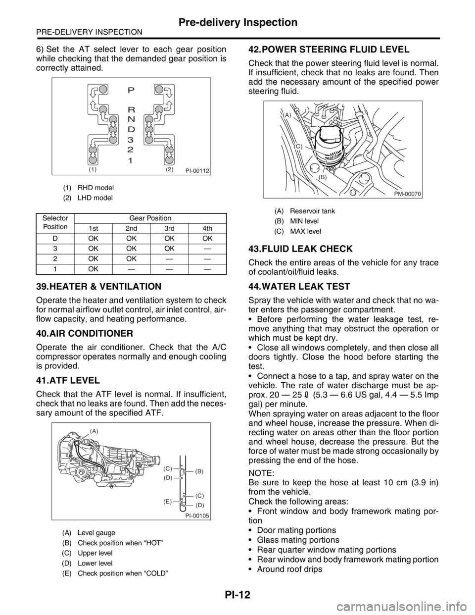
6) Set the AT select lever to each gear position
while checking that the demanded gear position is
correctly attained.
39.HEATER & VENTILATION
Operate the heater and ventilation system to check
for normal airflow outlet control, air inlet control, air-
flow capacity, and heating performance.
40.AIR CONDITIONER
Operate the air conditioner. Check that the A/C
compressor operates normally and enough cooling
is provided.
41.ATF LEVEL
Check that the ATF level is normal. If insufficient,
check that no leaks are found. Then add the neces-
sary amount of the specified ATF.
42.POWER STEERING FLUID LEVEL
Check that the power steering fluid level is normal.
If insufficient, check that no leaks are found. Then
add the necessary amount of the specified power
steering fluid.
43.FLUID LEAK CHECK
Check the entire areas of the vehicle for any trace
of coolant/oil/fluid leaks.
44.WATER LEAK TEST
Spray the vehicle with water and check that no wa-
ter enters the passenger compartment.
Before performing the water leakage test, re-
move anything that may obstruct the operation or
which must be kept dry.
Close all windows completely, and then close all
doors tightly. Close the hood before starting the
test.
Connect a hose to a tap, and spray water on the
vehicle. The rate of water discharge must be ap-
prox. 20 — 252 (5.3 — 6.6 US gal, 4.4 — 5.5 Imp
gal) per minute.
When spraying water on areas adjacent to the floor
and wheel house, increase the pressure. When di-
recting water on areas other than the floor portion
and wheel house, decrease the pressure. But the
force of water must be made strong occasionally by
pressing the end of the hose.
NOTE:
Be sure to keep the hose at least 10 cm (3.9 in)
from the vehicle.
Check the following areas:
Front window and body framework mating por-
tion
Door mating portions
Glass mating portions
Rear quarter window mating portions
Rear window and body framework mating portion
Around roof drips
(1) RHD model
(2) LHD model
Selector
Po si t io nGear Position
1st 2nd 3rd 4th
D OKOKOKOK
3 OKOKOK —
2OKOK——
1OK———
(A) Level gauge
(B) Check position when “HOT”
(C) Upper level
(D) Lower level
(E) Check position when “COLD”
PI-00112(1) (2)
P
R
N
D
3
2
1
PI-00105
COLD
LFHOT LF
(A)
(C)
(D)
(C)
(D)
(E)
(B)
(A) Reservoir tank
(B) MIN level
(C) MAX level
PM-00070
(A)
(C)
(B)
Page 780 of 2870
PM-43
PERIODIC MAINTENANCE SERVICE
Steering System (Power Steering)
7. HOSES OF OIL PUMP FOR DAMAGES
Check the pressure hose and return hose of oil
pump for crack, swell or damage. Replace the hose
with a new one if necessary.
CAUTION:
Prevent the hoses from revolving and/or turn-
ing when installing hoses.
8. POWER STEERING PIPES FOR DAM-
AGE
Check the power steering pipes for corrosion and
damage.
Replace the pipes with a new one if necessary.
9. GEARBOX BOOTS
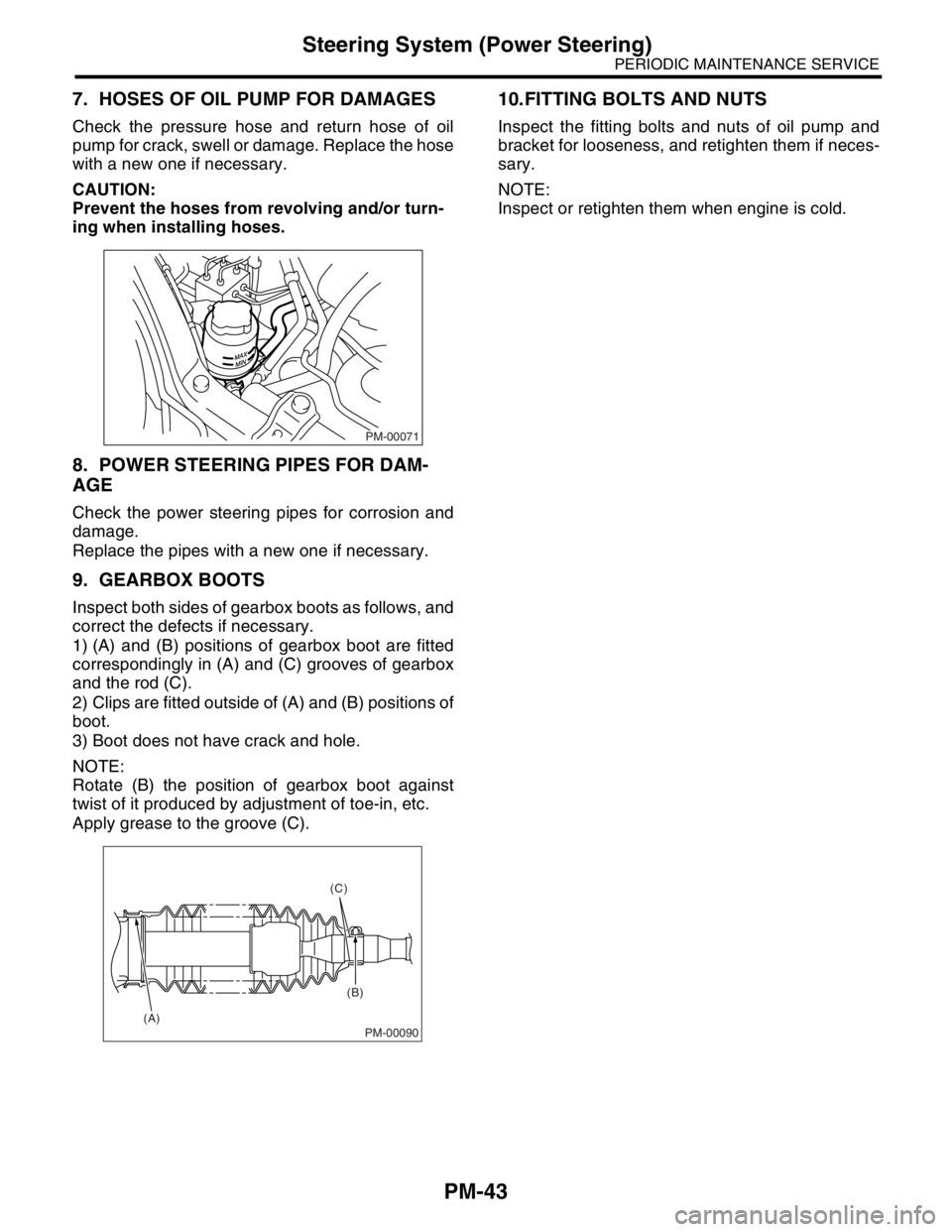
Inspect both sides of gearbox boots as follows, and
correct the defects if necessary.
1) (A) and (B) positions of gearbox boot are fitted
correspondingly in (A) and (C) grooves of gearbox
and the rod (C).
2) Clips are fitted outside of (A) and (B) positions of
boot.
3) Boot does not have crack and hole.
NOTE:
Rotate (B) the position of gearbox boot against
twist of it produced by adjustment of toe-in, etc.
Apply grease to the groove (C).
10.FITTING BOLTS AND NUTS
Inspect the fitting bolts and nuts of oil pump and
bracket for looseness, and retighten them if neces-
sary.
NOTE:
Inspect or retighten them when engine is cold.
PM-00071
PM-00090
(C)
(B)
(A)
Page 798 of 2870
FU(H4SO)-16
FUEL INJECTION (FUEL SYSTEM)
Intake Manifold
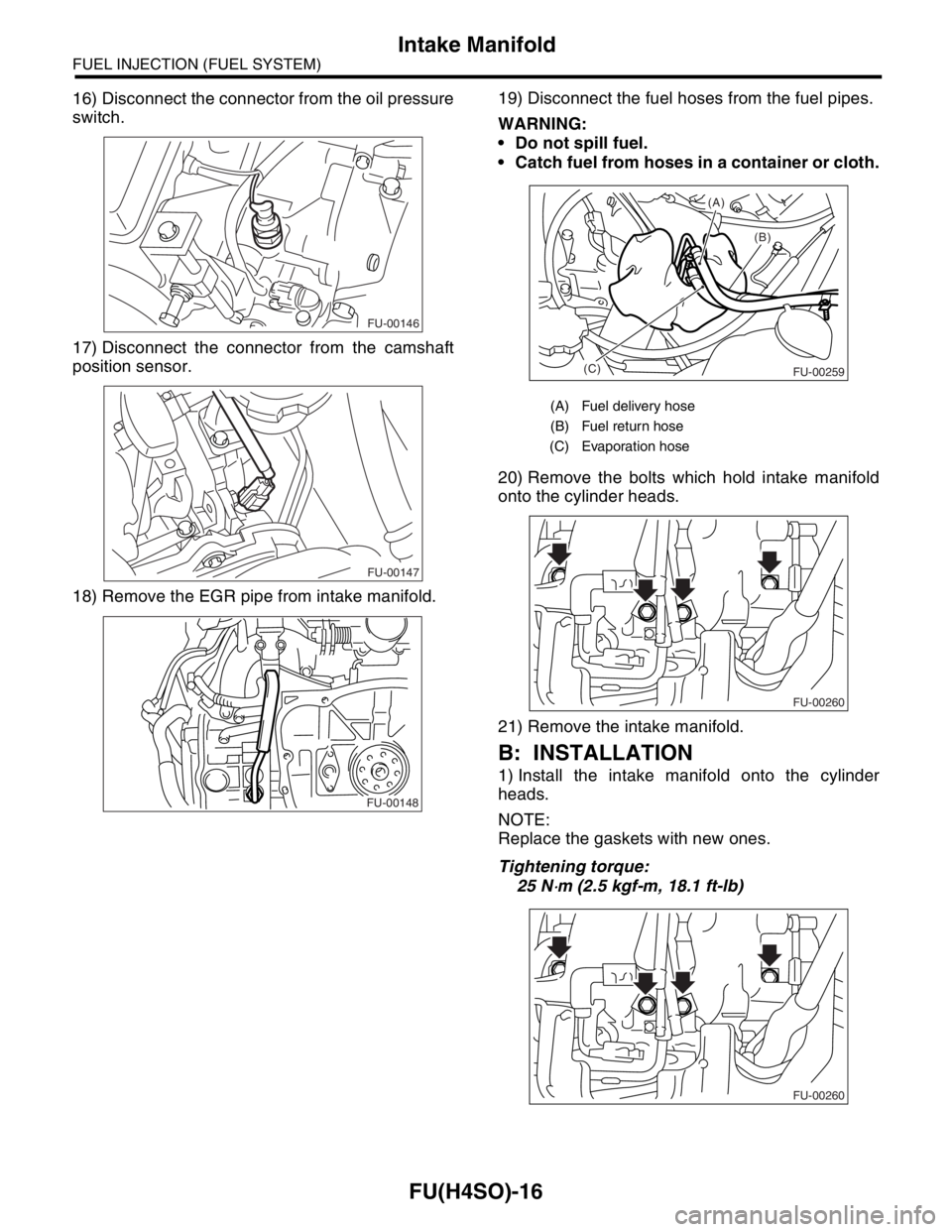
16) Disconnect the connector from the oil pressure
switch.
17) Disconnect the connector from the camshaft
position sensor.
18) Remove the EGR pipe from intake manifold.19) Disconnect the fuel hoses from the fuel pipes.
WARNING:
Do not spill fuel.
Catch fuel from hoses in a container or cloth.
20) Remove the bolts which hold intake manifold
onto the cylinder heads.
21) Remove the intake manifold.
B: INSTALLATION
1) Install the intake manifold onto the cylinder
heads.
NOTE:
Replace the gaskets with new ones.
Tightening torque:
25 N
⋅m (2.5 kgf-m, 18.1 ft-lb)
FU-00146
FU-00147
FU-00148
(A) Fuel delivery hose
(B) Fuel return hose
(C) Evaporation hose
(B) (A)
(C)
FU-00259
FU-00260
FU-00260
Page 799 of 2870
FU(H4SO)-17
FUEL INJECTION (FUEL SYSTEM)
Intake Manifold
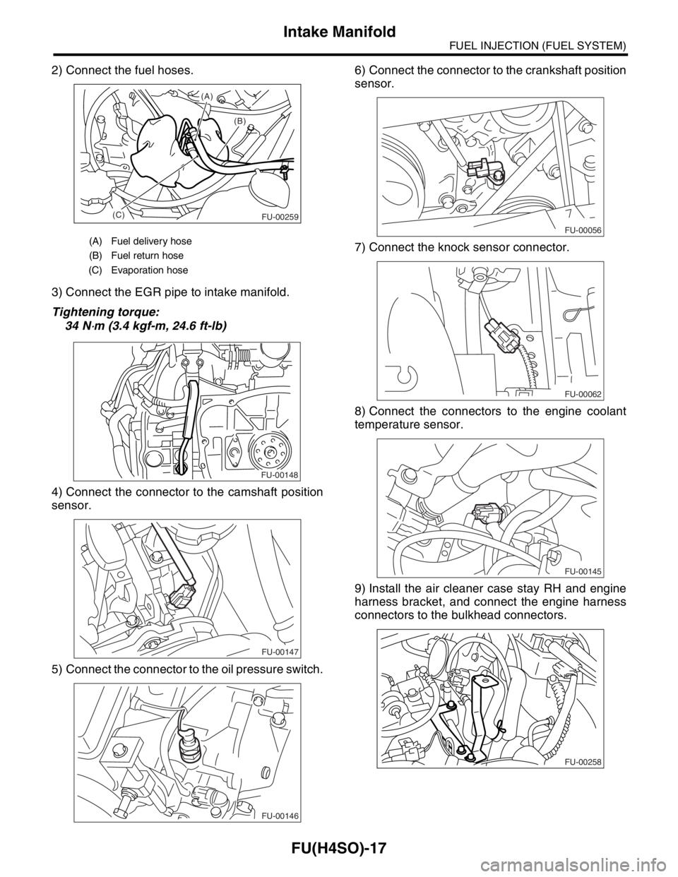
2) Connect the fuel hoses.
3) Connect the EGR pipe to intake manifold.
Tightening torque:
34 N
⋅m (3.4 kgf-m, 24.6 ft-lb)
4) Connect the connector to the camshaft position
sensor.
5) Connect the connector to the oil pressure switch.6) Connect the connector to the crankshaft position
sensor.
7) Connect the knock sensor connector.
8) Connect the connectors to the engine coolant
temperature sensor.
9) Install the air cleaner case stay RH and engine
harness bracket, and connect the engine harness
connectors to the bulkhead connectors.
(A) Fuel delivery hose
(B) Fuel return hose
(C) Evaporation hose
(B) (A)
(C)
FU-00259
FU-00148
FU-00147
FU-00146
FU-00056
FU-00062
FU-00145
FU-00258