2004 SUBARU FORESTER air pressure switch
[x] Cancel search: air pressure switchPage 3 of 2870

HVAC SYSTEM
(HEATER, VENTILATOR AND A/C)
AC
Page
1. General Description ....................................................................................2
2. Refrigerant Pressure with Manifold Gauge Set .........................................25
3. Refrigerant Recovery Procedure...............................................................26
4. Refrigerant Charging Procedure ...............................................................27
5. Refrigerant Leak Check ............................................................................30
6. Compressor Oil .........................................................................................31
7. Blower Motor Unit Assembly .....................................................................32
8. Blower Resistor (Manual A/C Model) ........................................................33
9. Heater Core...............................................................................................34
10. Control Unit ...............................................................................................35
11. Compressor...............................................................................................36
12. Condenser.................................................................................................37
13. Condenser (Sub Fan)................................................................................38
14. Heater Cooling Unit ...................................................................................39
15. Evaporator.................................................................................................40
16. Hose and Tube..........................................................................................41
17. Relay and Fuse .........................................................................................42
18. Pressure Switch (Triple Pressure Switch) .................................................43
19. Ambient Sensor (Auto A/C Model) ............................................................44
20. Sunload Sensor (Auto A/C Model) ............................................................45
21. Air Vent Grille ............................................................................................46
22. Heater Duct ...............................................................................................47
23. Heater Vent Duct.......................................................................................48
24. Heater Cock Solenoid Valve .....................................................................49
25. General Diagnostics ..................................................................................50
Page 5 of 2870
AC-3
HVAC SYSTEM (HEATER, VENTILATOR AND A/C)
General Description
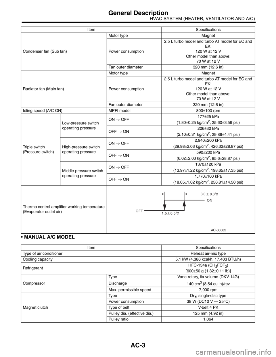
MANUAL A/C MODEL
Condenser fan (Sub fan)Motor type Magnet
Power consumption2.5 L turbo model and turbo AT model for EC and
EK:
120 W at 12 V
Other model than above:
70 W at 12 V
Fan outer diameter 320 mm (12.6 in)
Radiator fan (Main fan)Motor type Magnet
Power consumption2.5 L turbo model and turbo AT model for EC and
EK:
120 W at 12 V
Other model than above:
70 W at 12 V
Fan outer diameter 320 mm (12.6 in)
Idling speed (A/C ON) MPFI model 800±100 rpm
Triple switch
(Pressure switch)Low-pressure switch
operating pressureON → OFF177±25 kPa
(1.80±0.25 kg/cm
2, 25.60±3.56 psi)
OFF → ON206±30 kPa
(2.10±0.31 kg/cm
2, 29.86±4.41 psi)
High-pressure switch
operating pressureON → OFF2,940±200 kPa
(29.98±2.03 kg/cm
2, 426.32±28.87 psi)
OFF → ON590±200 kPa
(6.02±2.03 kg/cm
2, 85.6±28.87 psi)
Middle pressure switch
operating pressureON → OFF1370±120 kPa
(13.97±1.22 kg/cm
2, 198.65±17.35 psi)
OFF → ON1,770±100 kPa
(18.05±1.02 kg/cm
2, 256.81±14.50 psi)
Thermo control amplifier working temperature
(Evaporator outlet air)
Item Specifications
Type of air conditioner Reheat air-mix type
Cooling capacity 5.1 kW (4,386 kcal/h, 17,403 BTU/h)
RefrigerantHFC-134a (CH
2FCF3)
[600±50 g (1.32±0.11 lb)]
CompressorType Vane rotary, fix volume (DKV-14G)
Discharge
140 cm
3 (8.54 cu in)/rev
Max. permissible speed 7,000 rpm
Magnet clutchType Dry, single-disc type
Power consumption 38 W (DC12 V — 25°C)
Type of belt V-belt 4 PK
Pulley dia. (effective dia.) 125 mm (4.92 in)
Pulley ratio 1.064 Item Specifications
AC-00082
OFFON
3.0
0.3
Page 6 of 2870
AC-4
HVAC SYSTEM (HEATER, VENTILATOR AND A/C)
General Description
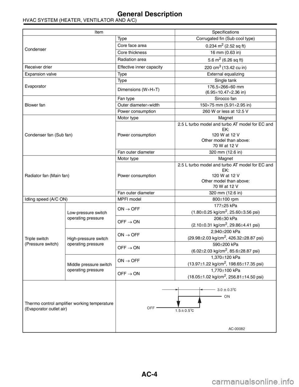
CondenserType Corrugated fin (Sub cool type)
Core face area
0.234 m
2 (2.52 sq ft)
Core thickness 16 mm (0.63 in)
Radiation area
5.6 m
2 (6.26 sq ft)
Receiver drier Effective inner capacity
220 cm
3 (13.42 cu in)
Expansion valve Type External equalizing
EvaporatorType Single tank
Dimensions (W×H×T)176.5×266×60 mm
(6.95×10.47×2.36 in)
Blower fanFan type Sirocco fan
Outer diameter×width 150×75 mm (5.91×2.95 in)
Power consumption 260 W or less at 12.5 V
Condenser fan (Sub fan)Motor type Magnet
Power consumption2.5 L turbo model and turbo AT model for EC and
EK:
120 W at 12 V
Other model than above:
70 W at 12 V
Fan outer diameter 320 mm (12.6 in)
Radiator fan (Main fan)Motor type Magnet
Power consumption2.5 L turbo model and turbo AT model for EC and
EK:
120 W at 12 V
Other model than above:
70 W at 12 V
Fan outer diameter 320 mm (12.6 in)
Idling speed (A/C ON) MPFI model 800±100 rpm
Triple switch
(Pressure switch)Low-pressure switch
operating pressureON → OFF177±25 kPa
(1.80±0.25 kg/cm
2, 25.60±3.56 psi)
OFF → ON206±30 kPa
(2.10±0.31 kg/cm
2, 29.86±4.41 psi)
High-pressure switch
operating pressureON → OFF2,940±200 kPa
(29.98±2.03 kg/cm
2, 426.32±28.87 psi)
OFF → ON590±200 kPa
(6.02±2.03 kg/cm
2, 85.6±28.87 psi)
Middle pressure switch
operating pressureON → OFF1,370±120 kPa
(13.97±1.22 kg/cm
2, 198.65±17.35 psi)
OFF → ON1,770±100 kPa
(18.05±1.02 kg/cm
2, 256.81±14.50 psi)
Thermo control amplifier working temperature
(Evaporator outlet air)Item Specifications
AC-00082
OFFON
3.0
0.3
Page 18 of 2870
AC-16
HVAC SYSTEM (HEATER, VENTILATOR AND A/C)
General Description
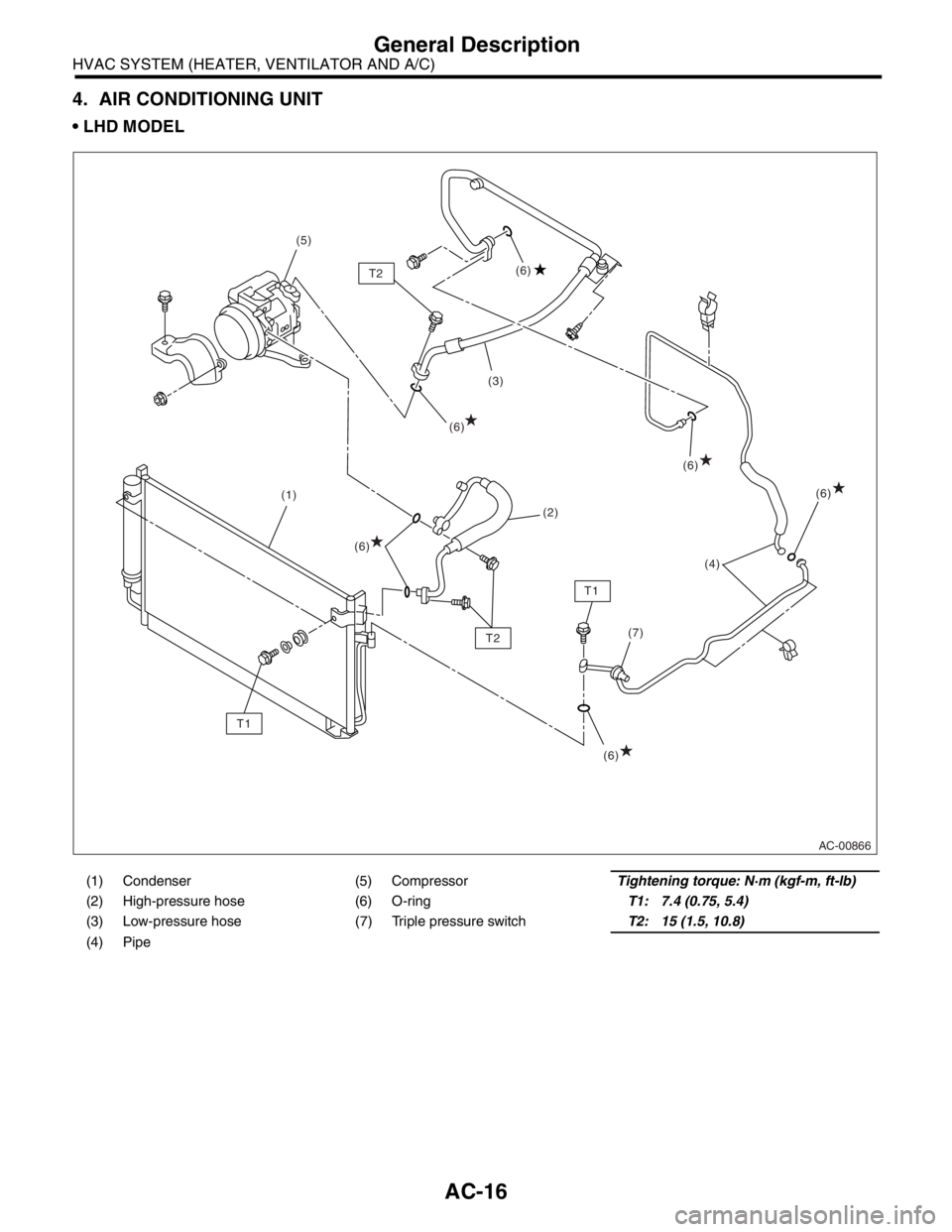
4. AIR CONDITIONING UNIT
LHD MODEL
(1) Condenser (5) CompressorTightening torque: N·m (kgf-m, ft-lb)
(2) High-pressure hose (6) O-ringT1: 7.4 (0.75, 5.4)
(3) Low-pressure hose (7) Triple pressure switchT2: 15 (1.5, 10.8)
(4) Pipe
AC-00866
(1)(3)
(4)
(7) (5)
(2)
T1
T1T2(6) (6)
(6)(6)
(6) T2(6)
Page 27 of 2870

AC-25
HVAC SYSTEM (HEATER, VENTILATOR AND A/C)
Refrigerant Pressure with Manifold Gauge Set
2. Refrigerant Pressure with Manifold Gauge Set
A: OPERATION
1) Place the vehicle in the shade and draftless condition.
2) Connect the manifold gauge set.
3) Open the front windows and close all doors.
4) Open the hood.
5) Increase the engine speed to 1,500 rpm.
6) Turn ON the A/C switch.
7) Turn the temperature control dial to MAX COOL.
8) Set the air inlet select switch to RECIRC position.
9) Turn the fan dial to HI.
10) Read the gauge.
Standard:
Low pressure: 127 — 196 kPa (1.3 — 2.0 kg/cm
2, 18 — 28 psi)
High pressure: 1,471 — 1, 667 kPa (15 — 17 kg/cm2, 213 — 242 psi)
Ambient temperature: 30 — 35
°C (86 — 95°F)
B: INSPECTION
Symptom Probable cause Repair order
High-pressure side is unusually high. Defective condenser fan motor
Clogged condenser fin
Too much refrigerant
Air inside the system
Defective receiver dryer Replace the fan motor.
Clean the condenser fin.
Discharge refrigerant.
Replace the receiver dryer.
After reevacuating the receiver dryer,
charge appropriate amount of refriger-
ant.
High-pressure side is unusually low. Defective compressor
Not enough refrigerant
Clogged expansion valve
Expansion valve frozen temporarily by
moisture Replace the compressor.
Check for leaks.
Replace the expansion valve.
Fully evacuate the expansion valve.
Low-pressure side is unusually high. Defective compressor
Defective expansion valve
Too much refrigerant Replace the compressor.
Replace the expansion valve.
Discharge refrigerant.
Low-pressure side is unusually low. Not enough refrigerant
Clogged expansion valve
Expansion valve frozen temporarily by
moisture
Saturated receiver dryer Check for leaks.
Replace the expansion valve.
Replace the receiver dryer.
Page 30 of 2870
AC-28
HVAC SYSTEM (HEATER, VENTILATOR AND A/C)
Refrigerant Charging Procedure
6) Leave it at least 5 to 10 minutes after closing the
valves on low-/high-pressure sides, and then check
the low-pressure gauge reading for any changes.
When the gauge reading changes, this is a sign of
leakage. Check the pipe or hose connector points,
and repair if necessary. Repeat the procedure from
1) after repairing the faulty part.
7) If there are no leaks, further evacuate the sys-
tem 20 to 30 minutes.
8) Close all valves and stop the vacuum pump.
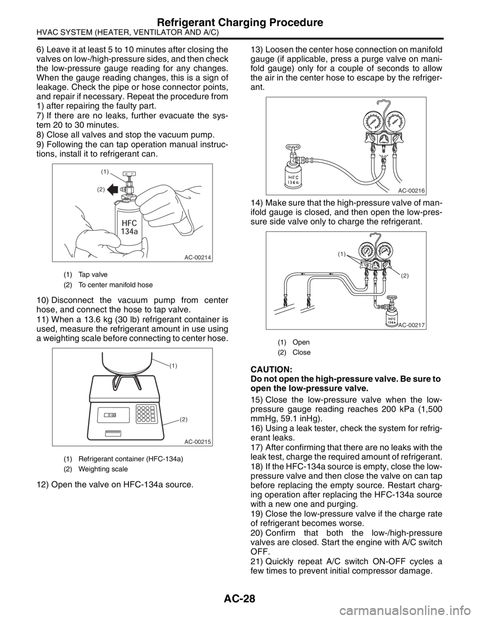
9) Following the can tap operation manual instruc-
tions, install it to refrigerant can.
10) Disconnect the vacuum pump from center
hose, and connect the hose to tap valve.
11) When a 13.6 kg (30 lb) refrigerant container is
used, measure the refrigerant amount in use using
a weighting scale before connecting to center hose.
12) Open the valve on HFC-134a source.13) Loosen the center hose connection on manifold
gauge (if applicable, press a purge valve on mani-
fold gauge) only for a couple of seconds to allow
the air in the center hose to escape by the refriger-
ant.
14) Make sure that the high-pressure valve of man-
ifold gauge is closed, and then open the low-pres-
sure side valve only to charge the refrigerant.
CAUTION:
Do not open the high-pressure valve. Be sure to
open the low-pressure valve.
15) Close the low-pressure valve when the low-
pressure gauge reading reaches 200 kPa (1,500
mmHg, 59.1 inHg).
16) Using a leak tester, check the system for refrig-
erant leaks.
17) After confirming that there are no leaks with the
leak test, charge the required amount of refrigerant.
18) If the HFC-134a source is empty, close the low-
pressure valve and then close the valve on can tap
before replacing the empty source. Restart charg-
ing operation after replacing the HFC-134a source
with a new one and purging.
19) Close the low-pressure valve if the charge rate
of refrigerant becomes worse.
20) Confirm that both the low-/high-pressure
valves are closed. Start the engine with A/C switch
OFF.
21) Quickly repeat A/C switch ON-OFF cycles a
few times to prevent initial compressor damage.
(1) Tap valve
(2) To center manifold hose
(1) Refrigerant container (HFC-134a)
(2) Weighting scale
AC-00214
(1)
(2)
AC-00215
(1)
(2)
(1) Open
(2) Close
AC-00216
AC-00217
(1)
(2)
Page 31 of 2870

AC-29
HVAC SYSTEM (HEATER, VENTILATOR AND A/C)
Refrigerant Charging Procedure
22) Set up the vehicle to the following status:
A/C switch ON
Engine running at 1,500 rpm
Blower speed setting to “HI”
Temperature setting to “MAX COOL”
Air inlet setting to “RECIRC”
Window open
23) Open the low-pressure valve and charge the
specified amount of refrigerant.
24) Close all valves and disconnect the hoses from
service port after charging the refrigerant.
25) Install the cap to service port.
Page 38 of 2870
AC-36
HVAC SYSTEM (HEATER, VENTILATOR AND A/C)
Compressor
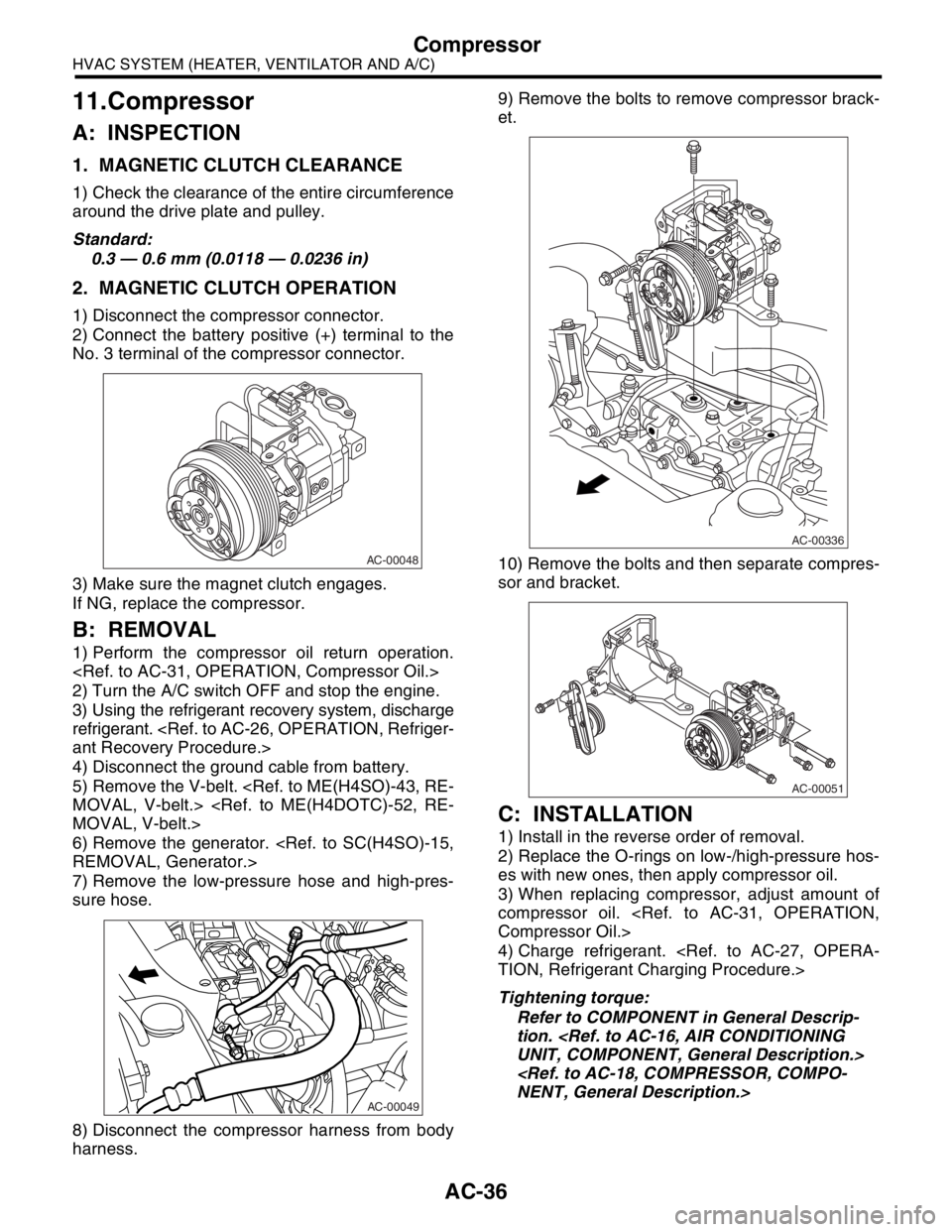
11.Compressor
A: INSPECTION
1. MAGNETIC CLUTCH CLEARANCE
1) Check the clearance of the entire circumference
around the drive plate and pulley.
Standard:
0.3 — 0.6 mm (0.0118 — 0.0236 in)
2. MAGNETIC CLUTCH OPERATION
1) Disconnect the compressor connector.
2) Connect the battery positive (+) terminal to the
No. 3 terminal of the compressor connector.
3) Make sure the magnet clutch engages.
If NG, replace the compressor.
B: REMOVAL
1) Perform the compressor oil return operation.
2) Turn the A/C switch OFF and stop the engine.
3) Using the refrigerant recovery system, discharge
refrigerant.
4) Disconnect the ground cable from battery.
5) Remove the V-belt.
6) Remove the generator.
7) Remove the low-pressure hose and high-pres-
sure hose.
8) Disconnect the compressor harness from body
harness.9) Remove the bolts to remove compressor brack-
et.
10) Remove the bolts and then separate compres-
sor and bracket.
C: INSTALLATION
1) Install in the reverse order of removal.
2) Replace the O-rings on low-/high-pressure hos-
es with new ones, then apply compressor oil.
3) When replacing compressor, adjust amount of
compressor oil.
4) Charge refrigerant.
Tightening torque:
Refer to COMPONENT in General Descrip-
tion.
AC-00048
AC-00049
AC-00336
AC-00051