Page 933 of 2870
ME(H4SO)-62
MECHANICAL
Cylinder Head
20.Cylinder Head
A: REMOVAL
1) Remove the V-belt.
MOVAL, V-belt.>
2) Remove the crank pulley.
45, REMOVAL, Crank Pulley.>
3) Remove the timing belt cover.
ME(H4SO)-47, REMOVAL, Timing Belt Cover.>
4) Remove the timing belt.
REMOVAL, Timing Belt.>
5) Remove the cam sprocket.
53, REMOVAL, Cam Sprocket.>
6) Remove the intake manifold.
14, REMOVAL, Intake Manifold.>
7) Remove the bolt which installs A/C compressor
bracket on cylinder head.
8) Remove the valve rocker assembly.
ME(H4SO)-56, REMOVAL, Valve Rocker Assem-
bly.>
9) Remove the camshaft.
REMOVAL, Camshaft.>
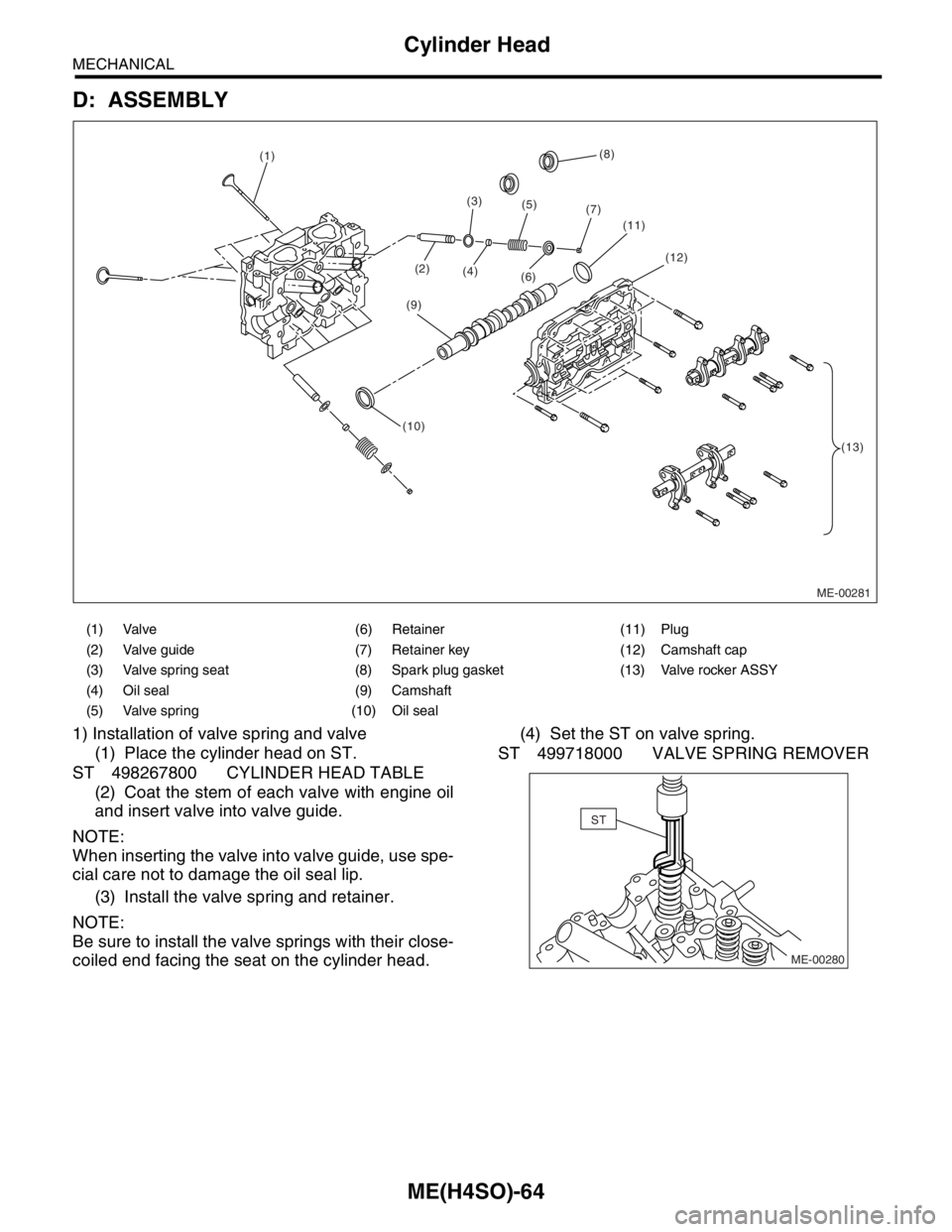
10) Remove the cylinder head bolts in alphabetical
sequence shown in the figure.
NOTE:
Leave the bolts (a) and (c) engaged by three or four
threads to prevent cylinder head from falling.
11) While tapping the cylinder head with a plastic
hammer, separate it from cylinder block.
12) Remove the bolts (a) and (c) to remove cylinder
head.
13) Remove the cylinder head gasket.CAUTION:
Do not scratch the mating surface of cylinder
head and cylinder block.
14) Similarly, remove the right side cylinder head.
B: INSTALLATION
1) Install the cylinder head and gaskets on cylinder
block.
CAUTION:
Use new cylinder head gaskets.
Be careful not to scratch the mating surface
of cylinder block and cylinder head.
2) Tighten the cylinder head bolts.
(1) Apply a coat of engine oil to washers and
bolt threads.
(2) Tighten all bolts to 29 N⋅m (3.0 kgf-m, 22 ft-
lb) in alphabetical sequence.
Then tighten all bolts to 69 N⋅m (7.0 kgf-m, 51 ft-
lb) in alphabetical sequence.
(3) Back off all bolts by 180° in reverse order of
installation, and back them off again by 180°.
(4) Tighten all bolts to 42 N⋅m (3.9 kgf-m, 31 ft-
lb) in alphabetical sequence.
(5) Tighten all bolts by 80° — 90° in alphabeti-
cal sequence.
(6) Tighten all bolts by 40° — 45° in alphabeti-
cal sequence.
NOTE:
Do not tighten the bolts more than 45°.
(7) Further tighten bolts (a) and (b) by 40° —
45°.
NOTE:
Ensure the total “re-tightening angle” in the [former
two steps], do not exceed 90°.
3) Install the camshaft.
STALLATION, Camshaft.>
4) Install the valve rocker assembly.
ME(H4SO)-56, INSTALLATION, Valve Rocker As-
sembly.>
5) Install the A/C compressor bracket on cylinder
head.
6) Install the intake manifold.
16, INSTALLATION, Intake Manifold.>
ME-00278
(c)
(b)
(f)
(d) (a)(e)
ME-00278
(c)
(b)
(f)
(d) (a)(e)
ME-00279
(c)
(b)(f)
(d) (a)
(e)
Page 935 of 2870
ME(H4SO)-64
MECHANICAL
Cylinder Head
D: ASSEMBLY
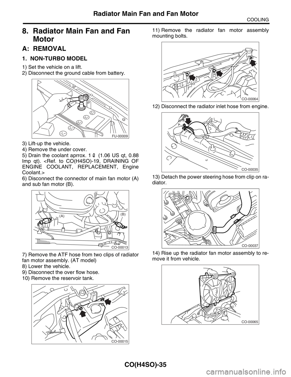
1) Installation of valve spring and valve
(1) Place the cylinder head on ST.
ST 498267800 CYLINDER HEAD TABLE
(2) Coat the stem of each valve with engine oil
and insert valve into valve guide.
NOTE:
When inserting the valve into valve guide, use spe-
cial care not to damage the oil seal lip.
(3) Install the valve spring and retainer.
NOTE:
Be sure to install the valve springs with their close-
coiled end facing the seat on the cylinder head.(4) Set the ST on valve spring.
ST 499718000 VALVE SPRING REMOVER
(1) Valve (6) Retainer (11) Plug
(2) Valve guide (7) Retainer key (12) Camshaft cap
(3) Valve spring seat (8) Spark plug gasket (13) Valve rocker ASSY
(4) Oil seal (9) Camshaft
(5) Valve spring (10) Oil seal
ME-00281 (10)(9)(6) (1)
(2)(3)
(4)(5)
(7)(8)
(11)
(13) (12)
ME-00280
ST
Page 952 of 2870
ME(H4SO)-81
MECHANICAL
Cylinder Block
Model with ATF warmer
28) Install the water by-pass pipe for heater.
29) Get a engine oil filter and apply a thin coat of
engine oil to the seal rubber.
30) Install the oil filter by turning it by hand, being
careful not to damage the seal rubber.
Tighten the oil filter 80 mm (3.15 in) or 65 mm
(2.56 in) in diameter by approx. 2/3 — 3/4 rotation
more after the seal rubber of oil filter comes in con-
tact with cylinder block or oil cooler.
Tighten the oil filter 68 mm (2.68 in) in diameter
by approx. 1 rotation more after the seal rubber of
oil filter comes in contact with cylinder block or oil
cooler.
CAUTION:
Do not tighten excessively, or oil may leak.
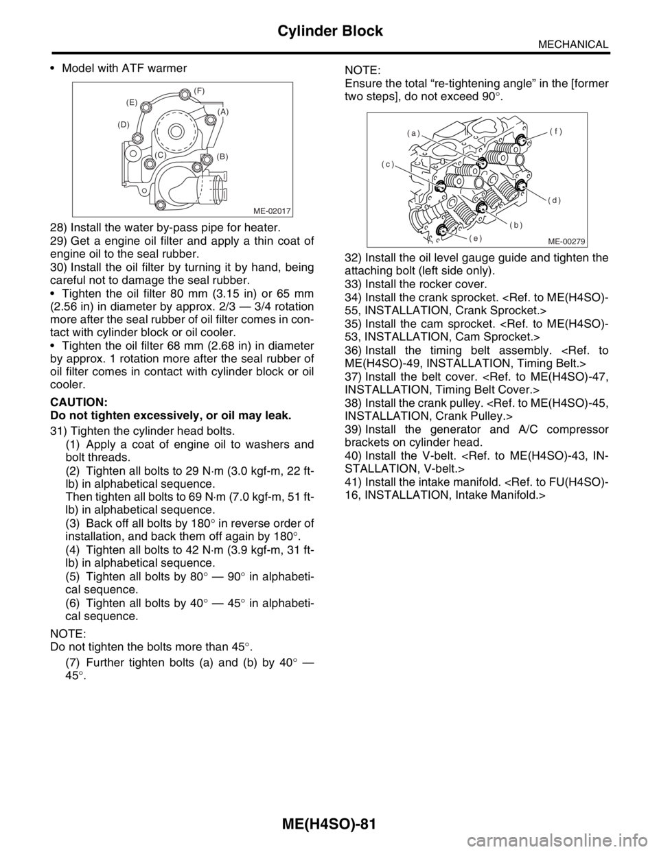
31) Tighten the cylinder head bolts.
(1) Apply a coat of engine oil to washers and
bolt threads.
(2) Tighten all bolts to 29 N⋅m (3.0 kgf-m, 22 ft-
lb) in alphabetical sequence.
Then tighten all bolts to 69 N⋅m (7.0 kgf-m, 51 ft-
lb) in alphabetical sequence.
(3) Back off all bolts by 180° in reverse order of
installation, and back them off again by 180°.
(4) Tighten all bolts to 42 N⋅m (3.9 kgf-m, 31 ft-
lb) in alphabetical sequence.
(5) Tighten all bolts by 80° — 90° in alphabeti-
cal sequence.
(6) Tighten all bolts by 40° — 45° in alphabeti-
cal sequence.
NOTE:
Do not tighten the bolts more than 45°.
(7) Further tighten bolts (a) and (b) by 40° —
45°.NOTE:
Ensure the total “re-tightening angle” in the [former
two steps], do not exceed 90°.
32) Install the oil level gauge guide and tighten the
attaching bolt (left side only).
33) Install the rocker cover.
34) Install the crank sprocket.
55, INSTALLATION, Crank Sprocket.>
35) Install the cam sprocket.
53, INSTALLATION, Cam Sprocket.>
36) Install the timing belt assembly.
ME(H4SO)-49, INSTALLATION, Timing Belt.>
37) Install the belt cover.
INSTALLATION, Timing Belt Cover.>
38) Install the crank pulley.
INSTALLATION, Crank Pulley.>
39) Install the generator and A/C compressor
brackets on cylinder head.
40) Install the V-belt.
STALLATION, V-belt.>
41) Install the intake manifold.
16, INSTALLATION, Intake Manifold.>
ME-02017
(B) (C) (D)(E)(F)
(A)
ME-00279
(c)
(b)(f)
(d) (a)
(e)
Page 1008 of 2870
CO(H4SO)-25
COOLING
Water Pump
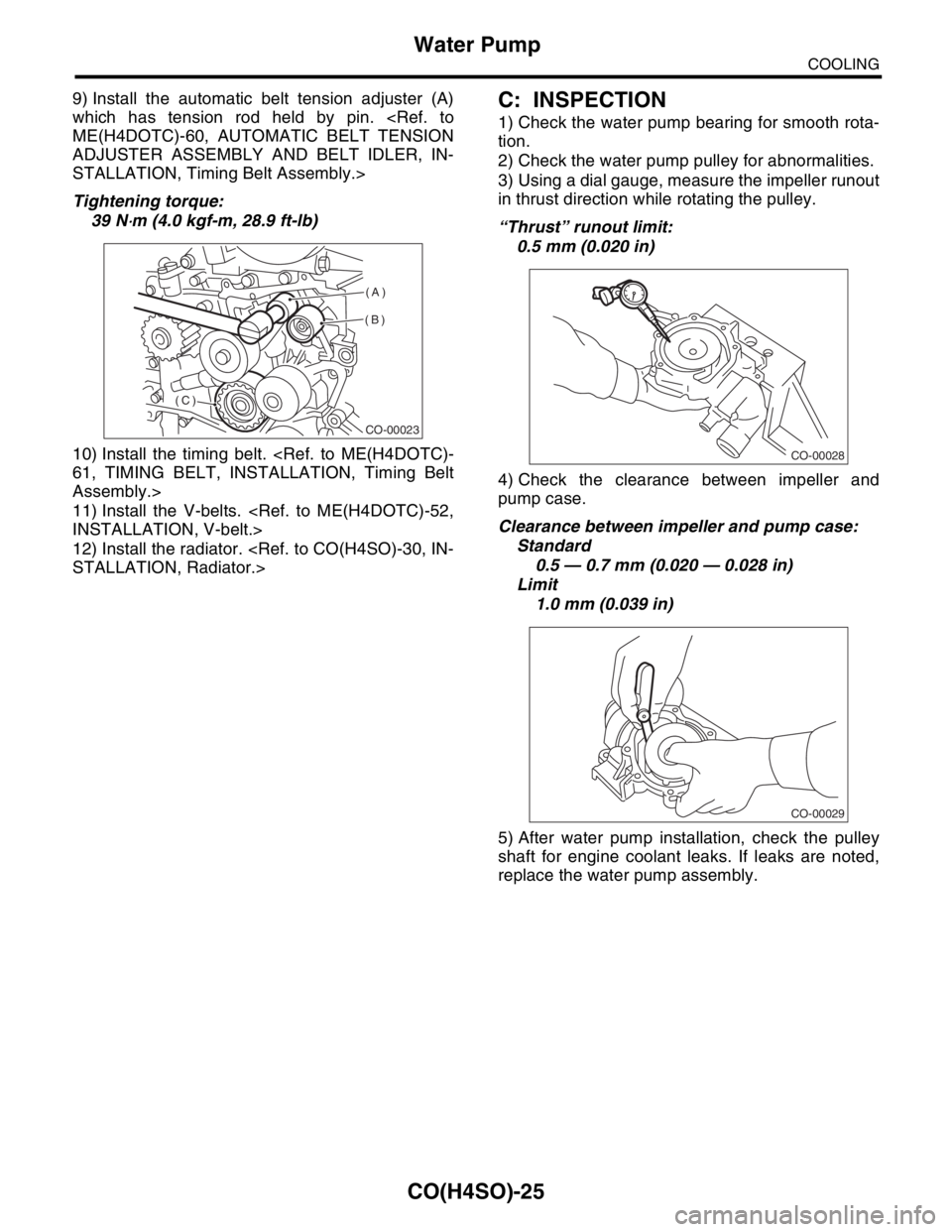
9) Install the automatic belt tension adjuster (A)
which has tension rod held by pin.
ME(H4DOTC)-60, AUTOMATIC BELT TENSION
ADJUSTER ASSEMBLY AND BELT IDLER, IN-
STALLATION, Timing Belt Assembly.>
Tightening torque:
39 N
⋅m (4.0 kgf-m, 28.9 ft-lb)
10) Install the timing belt.
61, TIMING BELT, INSTALLATION, Timing Belt
Assembly.>
11) Install the V-belts.
INSTALLATION, V-belt.>
12) Install the radiator.
STALLATION, Radiator.>
C: INSPECTION
1) Check the water pump bearing for smooth rota-
tion.
2) Check the water pump pulley for abnormalities.
3) Using a dial gauge, measure the impeller runout
in thrust direction while rotating the pulley.
“Thrust” runout limit:
0.5 mm (0.020 in)
4) Check the clearance between impeller and
pump case.
Clearance between impeller and pump case:
Standard
0.5 — 0.7 mm (0.020 — 0.028 in)
Limit
1.0 mm (0.039 in)
5) After water pump installation, check the pulley
shaft for engine coolant leaks. If leaks are noted,
replace the water pump assembly.
CO-00023
(A)
(B)
(C)
CO-00028
CO-00029
Page 1018 of 2870
CO(H4SO)-35
COOLING
Radiator Main Fan and Fan Motor
8. Radiator Main Fan and Fan
Motor
A: REMOVAL
1. NON-TURBO MODEL
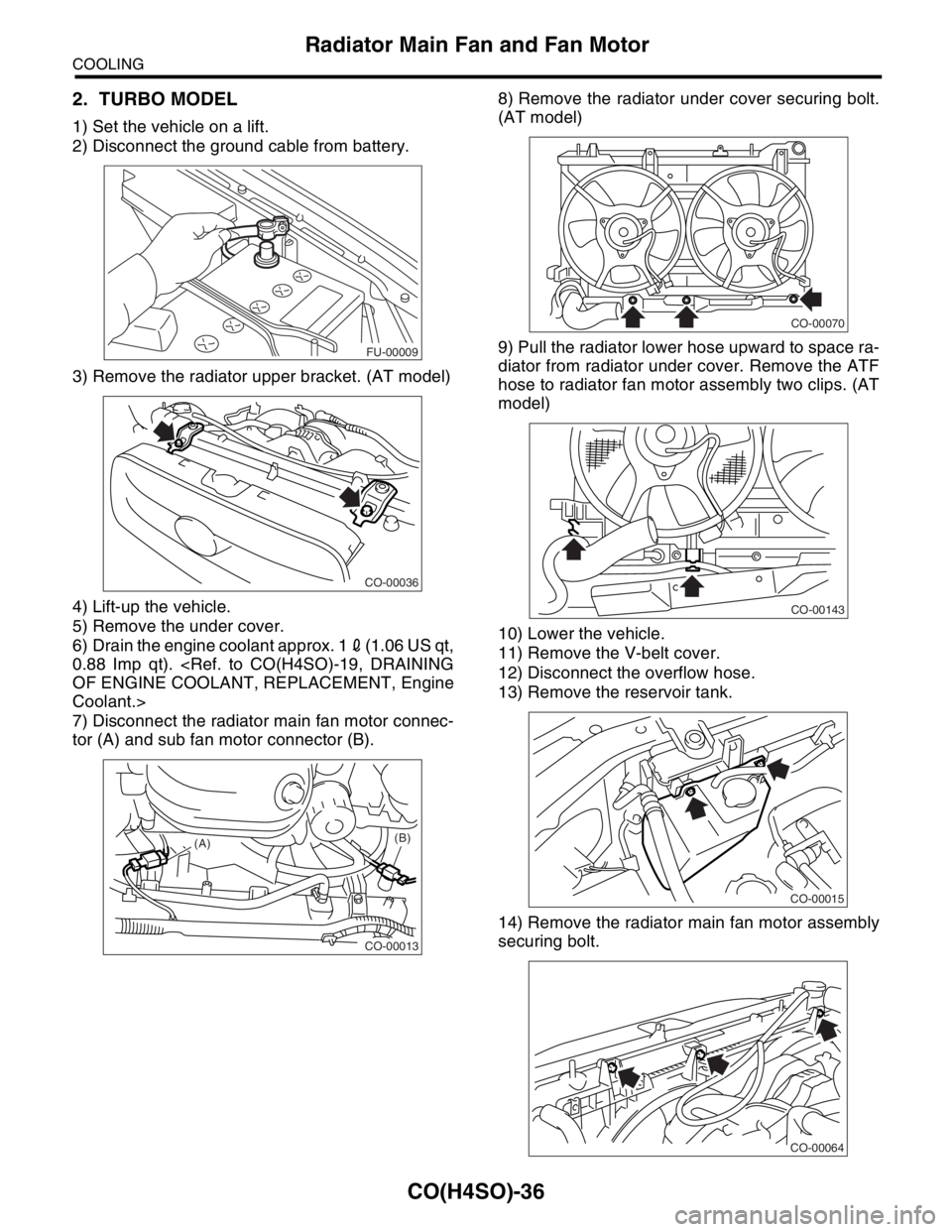
1) Set the vehicle on a lift.
2) Disconnect the ground cable from battery.
3) Lift-up the vehicle.
4) Remove the under cover.
5) Drain the coolant aprrox. 12 (1.06 US qt, 0.88
Imp qt).
ENGINE COOLANT, REPLACEMENT, Engine
Coolant.>
6) Disconnect the connector of main fan motor (A)
and sub fan motor (B).
7) Remove the ATF hose from two clips of radiator
fan motor assembly. (AT model)
8) Lower the vehicle.
9) Disconnect the over flow hose.
10) Remove the reservoir tank.11) Remove the radiator fan motor assembly
mounting bolts.
12) Disconnect the radiator inlet hose from engine.
13) Detach the power steering hose from clip on ra-
diator.
14) Rise up the radiator fan motor assembly to re-
move it from vehicle.
FU-00009
CO-00013
(A)(B)
CO-00015
CO-00064
CO-00035
CO-00037
CO-00065
Page 1019 of 2870
CO(H4SO)-36
COOLING
Radiator Main Fan and Fan Motor
2. TURBO MODEL
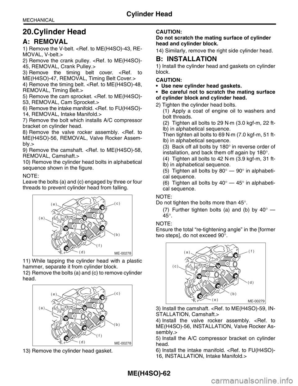
1) Set the vehicle on a lift.
2) Disconnect the ground cable from battery.
3) Remove the radiator upper bracket. (AT model)
4) Lift-up the vehicle.
5) Remove the under cover.
6) Drain the engine coolant approx. 12(1.06 US qt,
0.88 Imp qt).
OF ENGINE COOLANT, REPLACEMENT, Engine
Coolant.>
7) Disconnect the radiator main fan motor connec-
tor (A) and sub fan motor connector (B).8) Remove the radiator under cover securing bolt.
(AT model)
9) Pull the radiator lower hose upward to space ra-
diator from radiator under cover. Remove the ATF
hose to radiator fan motor assembly two clips. (AT
model)
10) Lower the vehicle.
11) Remove the V-belt cover.
12) Disconnect the overflow hose.
13) Remove the reservoir tank.
14) Remove the radiator main fan motor assembly
securing bolt.
FU-00009
CO-00036
CO-00013
(A)(B)
CO-00070
CO-00143
CO-00015
CO-00064
Page 1021 of 2870
CO(H4SO)-38
COOLING
Radiator Main Fan and Fan Motor
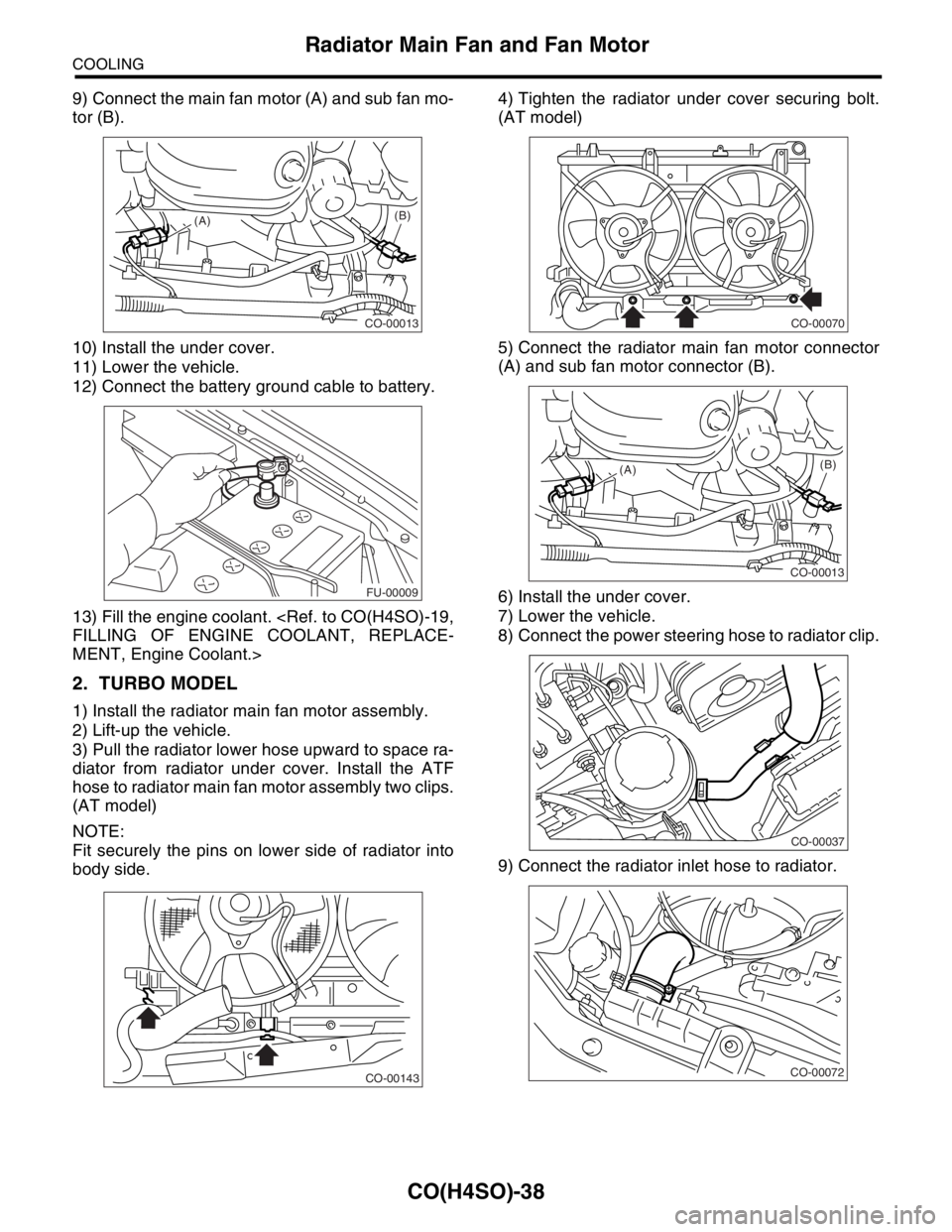
9) Connect the main fan motor (A) and sub fan mo-
tor (B).
10) Install the under cover.
11) Lower the vehicle.
12) Connect the battery ground cable to battery.
13) Fill the engine coolant.
FILLING OF ENGINE COOLANT, REPLACE-
MENT, Engine Coolant.>
2. TURBO MODEL
1) Install the radiator main fan motor assembly.
2) Lift-up the vehicle.
3) Pull the radiator lower hose upward to space ra-
diator from radiator under cover. Install the ATF
hose to radiator main fan motor assembly two clips.
(AT model)
NOTE:
Fit securely the pins on lower side of radiator into
body side.4) Tighten the radiator under cover securing bolt.
(AT model)
5) Connect the radiator main fan motor connector
(A) and sub fan motor connector (B).
6) Install the under cover.
7) Lower the vehicle.
8) Connect the power steering hose to radiator clip.
9) Connect the radiator inlet hose to radiator.
CO-00013
(A)(B)
FU-00009
CO-00143
CO-00070
CO-00013
(A)(B)
CO-00037
CO-00072
Page 1022 of 2870
CO(H4SO)-39
COOLING
Radiator Main Fan and Fan Motor
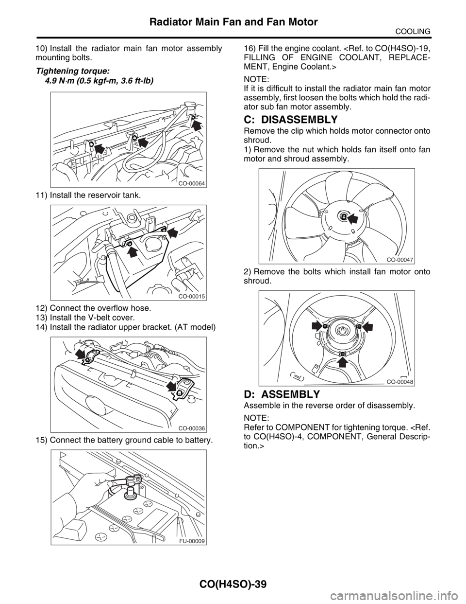
10) Install the radiator main fan motor assembly
mounting bolts.
Tightening torque:
4.9 N
⋅m (0.5 kgf-m, 3.6 ft-lb)
11) Install the reservoir tank.
12) Connect the overflow hose.
13) Install the V-belt cover.
14) Install the radiator upper bracket. (AT model)
15) Connect the battery ground cable to battery.16) Fill the engine coolant.
FILLING OF ENGINE COOLANT, REPLACE-
MENT, Engine Coolant.>
NOTE:
If it is difficult to install the radiator main fan motor
assembly, first loosen the bolts which hold the radi-
ator sub fan motor assembly.
C: DISASSEMBLY
Remove the clip which holds motor connector onto
shroud.
1) Remove the nut which holds fan itself onto fan
motor and shroud assembly.
2) Remove the bolts which install fan motor onto
shroud.
D: ASSEMBLY
Assemble in the reverse order of disassembly.
NOTE:
Refer to COMPONENT for tightening torque.
to CO(H4SO)-4, COMPONENT, General Descrip-
tion.>
CO-00064
CO-00015
CO-00036
FU-00009
CO-00047
CO-00048