Page 806 of 2870
FU(H4SO)-24
FUEL INJECTION (FUEL SYSTEM)
Intake Manifold
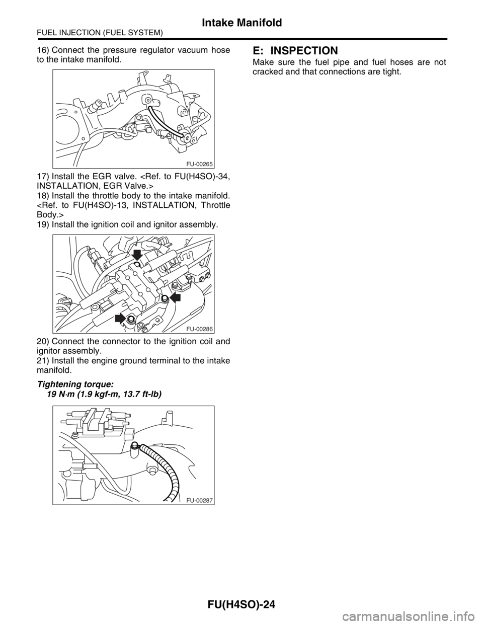
16) Connect the pressure regulator vacuum hose
to the intake manifold.
17) Install the EGR valve.
INSTALLATION, EGR Valve.>
18) Install the throttle body to the intake manifold.
Body.>
19) Install the ignition coil and ignitor assembly.
20) Connect the connector to the ignition coil and
ignitor assembly.
21) Install the engine ground terminal to the intake
manifold.
Tightening torque:
19 N
⋅m (1.9 kgf-m, 13.7 ft-lb)
E: INSPECTION
Make sure the fuel pipe and fuel hoses are not
cracked and that connections are tight.
FU-00265
FU-00286
FU-00287
Page 870 of 2870

MECHANICAL
ME(H4SO)
Page
1. General Description ....................................................................................2
2. Compression .............................................................................................25
3. Idle Speed .................................................................................................26
4. Ignition Timing ...........................................................................................27
5. Intake Manifold Vacuum............................................................................28
6. Engine Oil Pressure ..................................................................................29
7. Fuel Pressure ............................................................................................30
8. Valve Clearance ........................................................................................31
9. Engine Assembly ......................................................................................34
10. Engine Mounting .......................................................................................41
11. Preparation for Overhaul ...........................................................................42
12. V-belt .........................................................................................................43
13. Crank Pulley ..............................................................................................45
14. Timing Belt Cover......................................................................................47
15. Timing Belt ................................................................................................48
16. Cam Sprocket ...........................................................................................53
17. Crank Sprocket .........................................................................................55
18. Valve Rocker Assembly ............................................................................56
19. Camshaft ...................................................................................................58
20. Cylinder Head ...........................................................................................62
21. Cylinder Block ...........................................................................................69
22. Engine Trouble in General ........................................................................91
23. Engine Noise .............................................................................................96
Page 884 of 2870
ME(H4SO)-15
MECHANICAL
General Description
C: CAUTION
Wear working clothing, including a cap, protec-
tive goggles and protective shoes during operation.
Remove contamination including dirt and corro-
sion before removal, installation or disassembly.
Keep the disassembled parts in order and pro-
tect them from dust or dirt.
Before removal, installation or disassembly, be
sure to clarify the failure. Avoid unnecessary re-
moval, installation, disassembly and replacement.
Be careful not to burn yourself, because each
part in the vehicle is hot after running.
Be sure to tighten bolts and nuts to the specified
torque.
Place shop jacks or rigid racks at the specified
points.
Before disconnecting electrical connectors of
sensors or units, be sure to disconnect the ground
cable from battery.
All parts should be thoroughly cleaned, paying
special attention to the engine oil passages, pis-
tons and bearings. Rotating parts and sliding parts such as piston,
bearing and gear should be coated with oil prior to
assembly.
Be careful not to let oil, grease or coolant contact
the timing belt, clutch disc and flywheel.
All removed parts, if to be reused, should be re-
installed in the original positions and directions.
Bolts, nuts and washers should be replaced with
new ones as required.
Even if necessary inspections have been made
in advance, proceed with assembly work while
making rechecks.
Remove or install engine in an area where chain
hoists, lifting devices, etc. are available for ready
use.
Be sure not to damage coated surfaces of body
panels with tools, or not to stain seats and windows
with coolant or oil. Place a cover over fenders, as
required, for protection.
Prior to starting work, prepare the following:
Service tools, clean cloth, containers to catch cool-
ant and oil, wire ropes, chain hoist, transmission
jacks, etc.
Lift-up or lower the vehicle when necessary.
Make sure to support the correct positions.
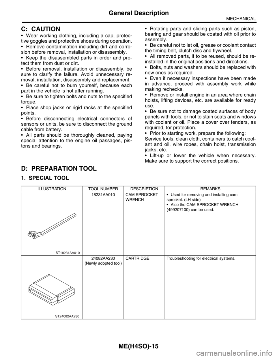
D: PREPARATION TOOL
1. SPECIAL TOOL
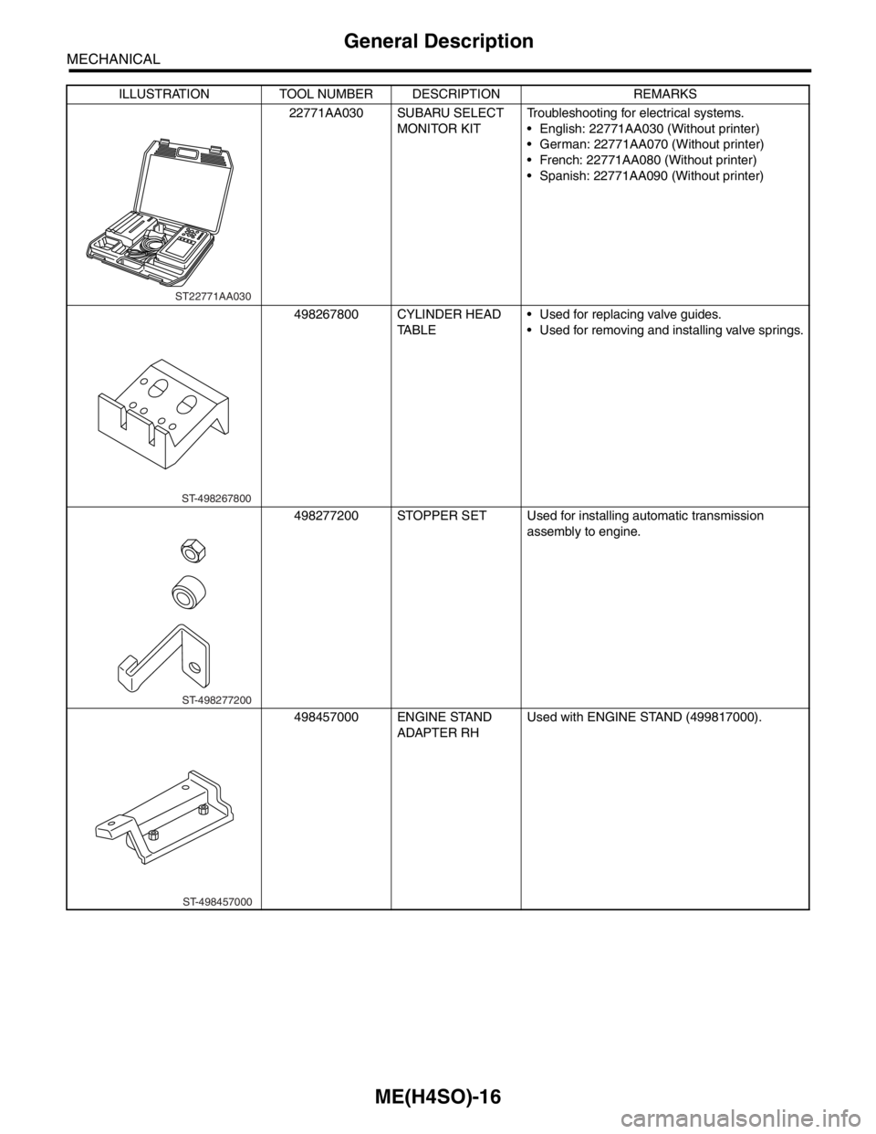
ILLUSTRATION TOOL NUMBER DESCRIPTION REMARKS
18231AA010 CAM SPROCKET
WRENCH Used for removing and installing cam
sprocket. (LH side)
Also the CAM SPROCKET WRENCH
(499207100) can be used.
24082AA230
(Newly adopted tool)CARTRIDGE Troubleshooting for electrical systems.
ST18231AA010
ST24082AA230
Page 885 of 2870
ME(H4SO)-16
MECHANICAL
General Description
22771AA030 SUBARU SELECT
MONITOR KITTroubleshooting for electrical systems.
English: 22771AA030 (Without printer)
German: 22771AA070 (Without printer)
French: 22771AA080 (Without printer)
Spanish: 22771AA090 (Without printer)
498267800 CYLINDER HEAD
TABLE Used for replacing valve guides.
Used for removing and installing valve springs.
498277200 STOPPER SET Used for installing automatic transmission
assembly to engine.
498457000 ENGINE STAND
ADAPTER RHUsed with ENGINE STAND (499817000). ILLUSTRATION TOOL NUMBER DESCRIPTION REMARKS
ST22771AA030
ST-498267800
ST-498277200
ST-498457000
Page 892 of 2870
ME(H4SO)-23
MECHANICAL
General Description
2. GENERAL TOOL
499817100 ENGINE STAND Stand used for engine disassembly and
assembly.
Used with ENGINE STAND ADAPTER RH
(498457000) & LH (498457100).
499977100 CRANK PULLEY
WRENCHUsed for stopping rotation of crank pulley when
loosening and tightening crank pulley bolts. (2.5
L model)
499977400 CRANK PULLEY
WRENCHUsed for stopping rotation of crank pulley when
loosening and tightening crank pulley bolts. (2.0
L model)
499987500 CRANKSHAFT
SOCKETUsed for rotating crankshaft.
TOOL NAME REMARKS
Compression gauge Used for measuring compression.
Tachometer (secondary pick-up type) Used for measuring idle speed.
Timing light Used for measuring ignition timing.ILLUSTRATION TOOL NUMBER DESCRIPTION REMARKS
ST-499817100
ST-499977100
ST-499977400
ST-499987500
Page 893 of 2870
ME(H4SO)-24
MECHANICAL
General Description
E: PROCEDURE
It is possible to conduct the following service proce-
dures with engine on the vehicle, however, the pro-
cedures described in this section are based on the
condition that the engine is removed from the vehi-
cle.
V-belt
Timing Belt
Valve Rocker Assembly
Camshaft
Cylinder Head
Page 903 of 2870
ME(H4SO)-34
MECHANICAL
Engine Assembly
9. Engine Assembly
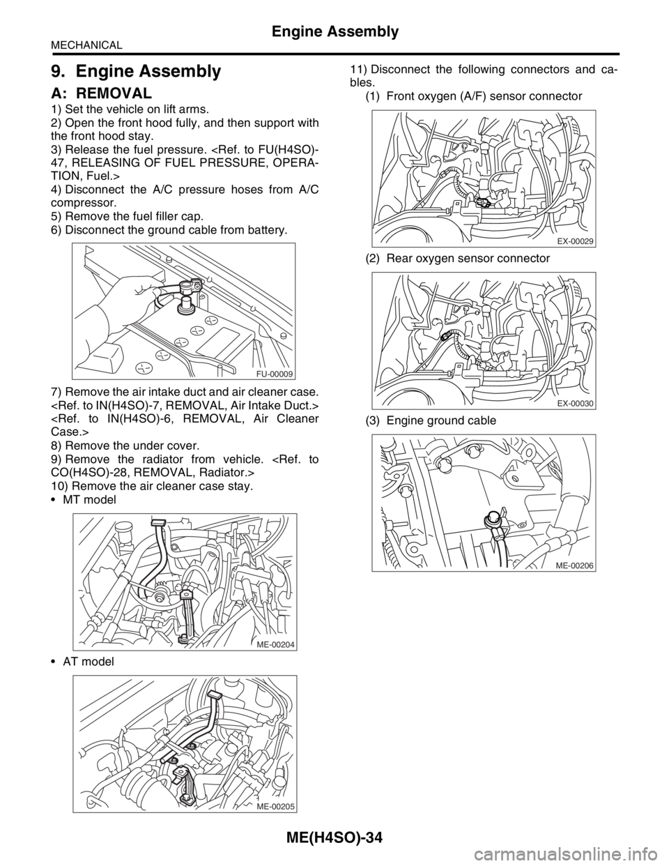
A: REMOVAL
1) Set the vehicle on lift arms.
2) Open the front hood fully, and then support with
the front hood stay.
3) Release the fuel pressure.
47, RELEASING OF FUEL PRESSURE, OPERA-
TION, Fuel.>
4) Disconnect the A/C pressure hoses from A/C
compressor.
5) Remove the fuel filler cap.
6) Disconnect the ground cable from battery.
7) Remove the air intake duct and air cleaner case.
Case.>
8) Remove the under cover.
9) Remove the radiator from vehicle.
CO(H4SO)-28, REMOVAL, Radiator.>
10) Remove the air cleaner case stay.
MT model
AT model11) Disconnect the following connectors and ca-
bles.
(1) Front oxygen (A/F) sensor connector
(2) Rear oxygen sensor connector
(3) Engine ground cable
FU-00009
ME-00204
ME-00205
EX-00029
EX-00030
ME-00206
Page 904 of 2870
ME(H4SO)-35
MECHANICAL
Engine Assembly
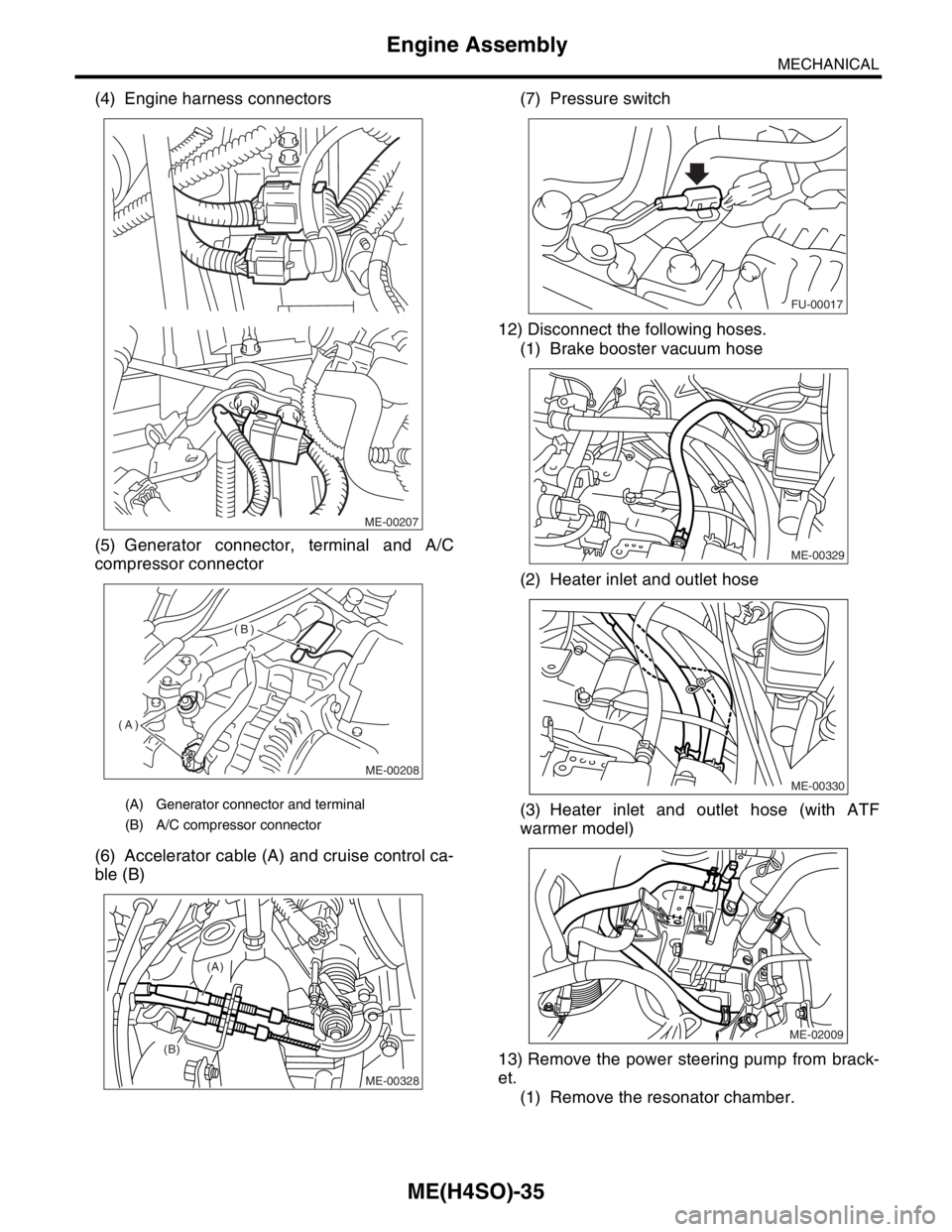
(4) Engine harness connectors
(5) Generator connector, terminal and A/C
compressor connector
(6) Accelerator cable (A) and cruise control ca-
ble (B)(7) Pressure switch
12) Disconnect the following hoses.
(1) Brake booster vacuum hose
(2) Heater inlet and outlet hose
(3) Heater inlet and outlet hose (with ATF
warmer model)
13) Remove the power steering pump from brack-
et.
(1) Remove the resonator chamber.
(A) Generator connector and terminal
(B) A/C compressor connector
ME-00207
ME-00208
(A)
(B)
(B)(A)
ME-00328
FU-00017
ME-00329
ME-00330
ME-02009