2004 SUBARU FORESTER instrument panel
[x] Cancel search: instrument panelPage 1672 of 2870
EN(H4DOTC)-42
ENGINE (DIAGNOSTIC)
Inspection Mode
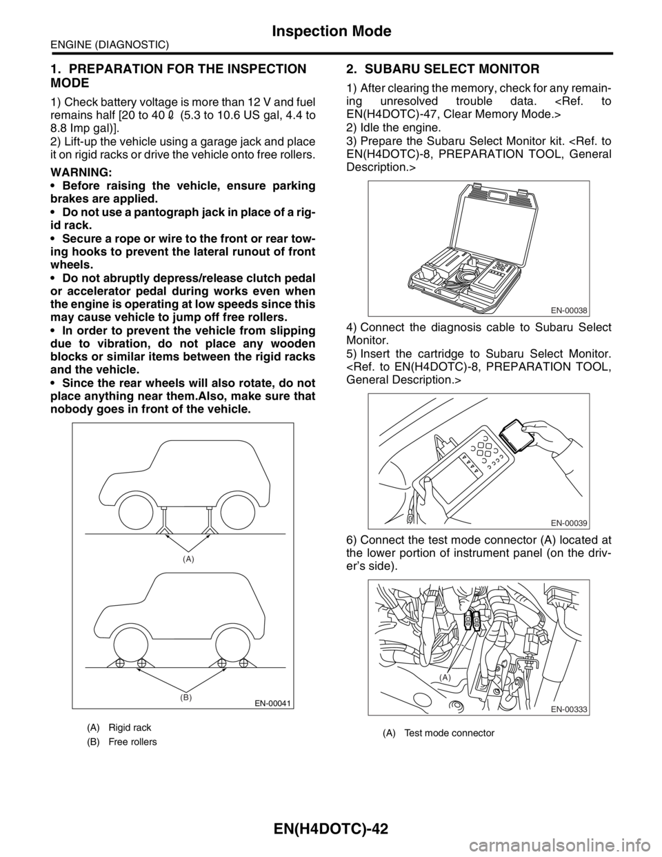
1. PREPARATION FOR THE INSPECTION
MODE
1) Check battery voltage is more than 12 V and fuel
remains half [20 to 402 (5.3 to 10.6 US gal, 4.4 to
8.8 Imp gal)].
2) Lift-up the vehicle using a garage jack and place
it on rigid racks or drive the vehicle onto free rollers.
WARNING:
Before raising the vehicle, ensure parking
brakes are applied.
Do not use a pantograph jack in place of a rig-
id rack.
Secure a rope or wire to the front or rear tow-
ing hooks to prevent the lateral runout of front
wheels.
Do not abruptly depress/release clutch pedal
or accelerator pedal during works even when
the engine is operating at low speeds since this
may cause vehicle to jump off free rollers.
In order to prevent the vehicle from slipping
due to vibration, do not place any wooden
blocks or similar items between the rigid racks
and the vehicle.
Since the rear wheels will also rotate, do not
place anything near them.Also, make sure that
nobody goes in front of the vehicle.
2. SUBARU SELECT MONITOR
1) After clearing the memory, check for any remain-
ing unresolved trouble data.
2) Idle the engine.
3) Prepare the Subaru Select Monitor kit.
Description.>
4) Connect the diagnosis cable to Subaru Select
Monitor.
5) Insert the cartridge to Subaru Select Monitor.
6) Connect the test mode connector (A) located at
the lower portion of instrument panel (on the driv-
er’s side).
(A) Rigid rack
(B) Free rollers
EN-00041
(A)
(B)
(A) Test mode connector
EN-00038
EN-00039
EN-00333
(A)
Page 1673 of 2870
EN(H4DOTC)-43
ENGINE (DIAGNOSTIC)
Inspection Mode
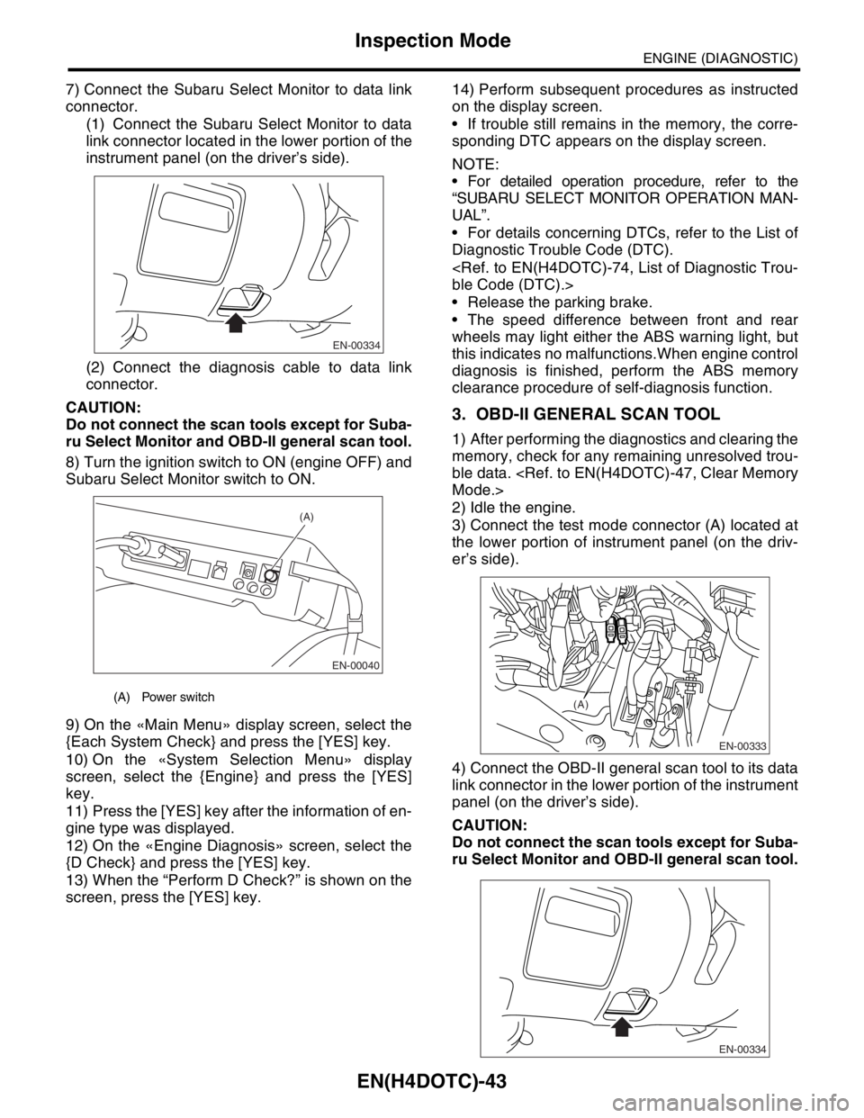
7) Connect the Subaru Select Monitor to data link
connector.
(1) Connect the Subaru Select Monitor to data
link connector located in the lower portion of the
instrument panel (on the driver’s side).
(2) Connect the diagnosis cable to data link
connector.
CAUTION:
Do not connect the scan tools except for Suba-
ru Select Monitor and OBD-II general scan tool.
8) Turn the ignition switch to ON (engine OFF) and
Subaru Select Monitor switch to ON.
9) On the «Main Menu» display screen, select the
{Each System Check} and press the [YES] key.
10) On the «System Selection Menu» display
screen, select the {Engine} and press the [YES]
key.
11) Press the [YES] key after the information of en-
gine type was displayed.
12) On the «Engine Diagnosis» screen, select the
{D Check} and press the [YES] key.
13) When the “Perform D Check?” is shown on the
screen, press the [YES] key.14) Perform subsequent procedures as instructed
on the display screen.
If trouble still remains in the memory, the corre-
sponding DTC appears on the display screen.
NOTE:
For detailed operation procedure, refer to the
“SUBARU SELECT MONITOR OPERATION MAN-
UAL”.
For details concerning DTCs, refer to the List of
Diagnostic Trouble Code (DTC).
Release the parking brake.
The speed difference between front and rear
wheels may light either the ABS warning light, but
this indicates no malfunctions.When engine control
diagnosis is finished, perform the ABS memory
clearance procedure of self-diagnosis function.
3. OBD-II GENERAL SCAN TOOL
1) After performing the diagnostics and clearing the
memory, check for any remaining unresolved trou-
ble data.
2) Idle the engine.
3) Connect the test mode connector (A) located at
the lower portion of instrument panel (on the driv-
er’s side).
4) Connect the OBD-II general scan tool to its data
link connector in the lower portion of the instrument
panel (on the driver’s side).
CAUTION:
Do not connect the scan tools except for Suba-
ru Select Monitor and OBD-II general scan tool.
(A) Power switch
EN-00334
EN-00040
(A)
EN-00333
(A)
EN-00334
Page 1678 of 2870
EN(H4DOTC)-48
ENGINE (DIAGNOSTIC)
Compulsory Valve Operation Check Mode
15.Compulsory Valve Operation
Check Mode
A: OPERATION
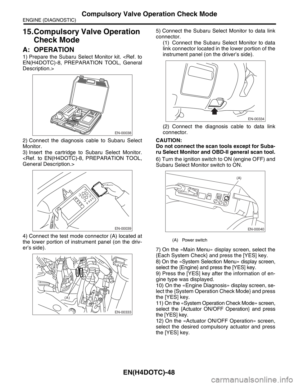
1) Prepare the Subaru Select Monitor kit.
Description.>
2) Connect the diagnosis cable to Subaru Select
Monitor.
3) Insert the cartridge to Subaru Select Monitor.
4) Connect the test mode connector (A) located at
the lower portion of instrument panel (on the driv-
er’s side).5) Connect the Subaru Select Monitor to data link
connector.
(1) Connect the Subaru Select Monitor to data
link connector located in the lower portion of the
instrument panel (on the driver’s side).
(2) Connect the diagnosis cable to data link
connector.
CAUTION:
Do not connect the scan tools except for Suba-
ru Select Monitor and OBD-II general scan tool.
6) Turn the ignition switch to ON (engine OFF) and
Subaru Select Monitor switch to ON.
7) On the «Main Menu» display screen, select the
{Each System Check} and press the [YES] key.
8) On the «System Selection Menu» display screen,
select the {Engine} and press the [YES] key.
9) Press the [YES] key after the information of en-
gine type was displayed.
10) On the «Engine Diagnosis» display screen, se-
lect the {System Operation Check Mode} and press
the [YES] key.
11) On the «System Operation Check Mode» screen,
select the {Actuator ON/OFF Operation} and press
the [YES] key.
12) On the «Actuator ON/OFF Operation» screen,
select the desired compulsory actuator and press
the [YES] key.
EN-00038
EN-00039
EN-00333
(A)
(A) Power switch
EN-00334
EN-00040
(A)
Page 1824 of 2870

EN(H4DOTC)-191
ENGINE (DIAGNOSTIC)
Diagnostic Procedure with Diagnostic Trouble Code (DTC)
Step Check Yes No
1 CHECK OUTPUT SIGNAL FROM ECM.
1) Turn the ignition switch to OFF.
2) Connect the test mode connector at the
lower portion of instrument panel (on the
driver’s side).
3) Turn the ignition switch to ON.
4) While operating the purge control solenoid
valve, measure voltage between ECM and
chassis ground.
N
OTE:
Purge control solenoid valve operation can be
executed using Subaru Select Monitor.For the
procedure, refer to “Compulsory Valve Opera-
tion Check Mode”.
Connector & terminal
(B134) No. 14 (+) — Chassis ground (
−):Is the voltage 0 — 13 V? Go to step 2.Even if the mal-
function indicator
light illuminates,
the circuit has
returned to a nor-
mal condition at
this time.In this
case, repair poor
contact in ECM
connector.
2 CHECK OUTPUT SIGNAL FROM ECM.
1) Turn the ignition switch to ON.
2) Measure the voltage between ECM and
chassis ground.
Connector & terminal
(B134) No. 14 (+) — Chassis ground (
−):Is the voltage more than 10 V? Go to step 4.Go to step 3.
3 CHECK POOR CONTACT.
Check poor contact in ECM connector. Is there poor contact in ECM
connector?Repair the poor
contact in ECM
connector.Replace the ECM.
Engine Control
Module (ECM).>
4 CHECK HARNESS BETWEEN PURGE CON-
TROL SOLENOID VALVE AND ECM CON-
NECTOR.
1) Turn the ignition switch to OFF.
2) Disconnect the connector from purge con-
trol solenoid valve.
3) Turn the ignition switch to ON.
4) Measure the voltage between ECM and
chassis ground.
Connector & terminal
(B134) No. 14 (+) — Chassis ground (
−):Is the voltage more than 10 V? Repair battery
short circuit in har-
ness between
ECM and purge
control solenoid
valve connec-
tor.After repair,
replace the ECM.
Engine Control
Module (ECM).>Go to step 5.
5 CHECK PURGE CONTROL SOLENOID
VALVE.
1) Turn the ignition switch to OFF.
2) Measure the resistance between purge
control solenoid valve terminals.
Te r m i n a l s
No. 1 — No. 2:Is the resistance less than 1
Ω?Replace the purge
control solenoid
valve and ECM.
Purge Control
Solenoid Valve.>
Engine Control
Module (ECM).>Go to step 6.
6 CHECK POOR CONTACT.
Check poor contact in ECM connector.Is there poor contact in ECM
connector?Repair the poor
contact in ECM
connector.Replace the ECM.
Engine Control
Module (ECM).>
Page 2029 of 2870
EN(H4DOTC 2.5)-5
ENGINE (DIAGNOSTIC)
General Description
3. General Description
A: CAUTION
1) Airbag system wiring harness is routed near the
ECM, main relay and fuel pump relay.
CAUTION:
All airbag system wiring harness and con-
nectors are all colored yellow. Do not use the
electrical test equipment on these circuits.
Be careful not to damage the Airbag system
wiring harness when servicing the ECM, TCM,
main relay and fuel pump relay.
2) Never connect the battery in reverse polarity.
The ECM will be destroyed immediately.
The fuel injector and other part will be damaged.
3) Do not disconnect the battery terminals while the
engine is running.
A large counter electromotive force will be gener-
ated in the generator, and this voltage may damage
electronic parts such as ECM, etc.
4) Before disconnecting the connectors of each
sensor and the ECM, be sure to turn OFF the igni-
tion switch.
5) Poor contact has been identified as a primary
cause of this problem. Measure the voltage or re-
sistance of individual sensor or all electrical control
modules using a tapered pin with a diameter of less
than 0.64 mm (0.025 in). Do not insert the pin more
than 5 mm (0.20 in) into the part.
6) Remove the ECM from the located position after
disconnecting two cables on battery.
Otherwise, the ECM may be damaged.
CAUTION:
When replacing the ECM, be careful not to use
the wrong spec. ECM to avoid damaging the
fuel injection system.
7) Connectors to each sensor in the engine com-
partment and the harness connectors on the en-
gine side and body side are all designed to be
waterproof. However, take care not to allow water
to get into the connectors when washing the vehi-
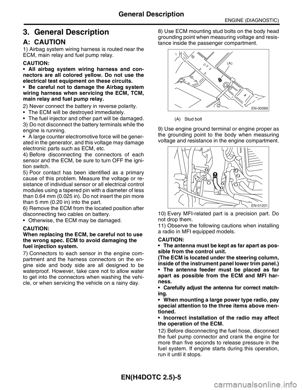
cle, or when servicing the vehicle on a rainy day. 8) Use ECM mounting stud bolts on the body head
grounding point when measuring voltage and resis-
tance inside the passenger compartment.
9) Use engine ground terminal or engine proper as
the grounding point to the body when measuring
voltage and resistance in the engine compartment.
10) Every MFI-related part is a precision part. Do
not drop them.
11) Observe the following cautions when installing
a radio in MFI equipped models.
CAUTION:
The antenna must be kept as far apart as pos-
sible from the control unit.
(The ECM is located under the steering column,
inside of the instrument panel lower trim panel.)
The antenna feeder must be placed as far
apart as possible from the ECM and MFI har-
ness.
Carefully adjust the antenna for correct match-
ing.
When mounting a large power type radio, pay
special attention to the three items above men-
tioned.
Incorrect installation of the radio may affect
the operation of the ECM.
12) Before disconnecting the fuel hose, disconnect
the fuel pump connector and crank the engine for
more than five seconds to release pressure in the
fuel system. If engine starts during this operation,
run it until it stops.
(A) Stud bolt
EN-00069
(A)
EN-01201
Page 2048 of 2870
EN(H4DOTC 2.5)-24
ENGINE (DIAGNOSTIC)
OBD-II General Scan Tool
8. OBD-II General Scan Tool
A: OPERATION
1. HOW TO USE OBD-II GENERAL SCAN
TOOL
1) Prepare a general scan tool (OBD-II general
scan tool) required by SAE J1978.
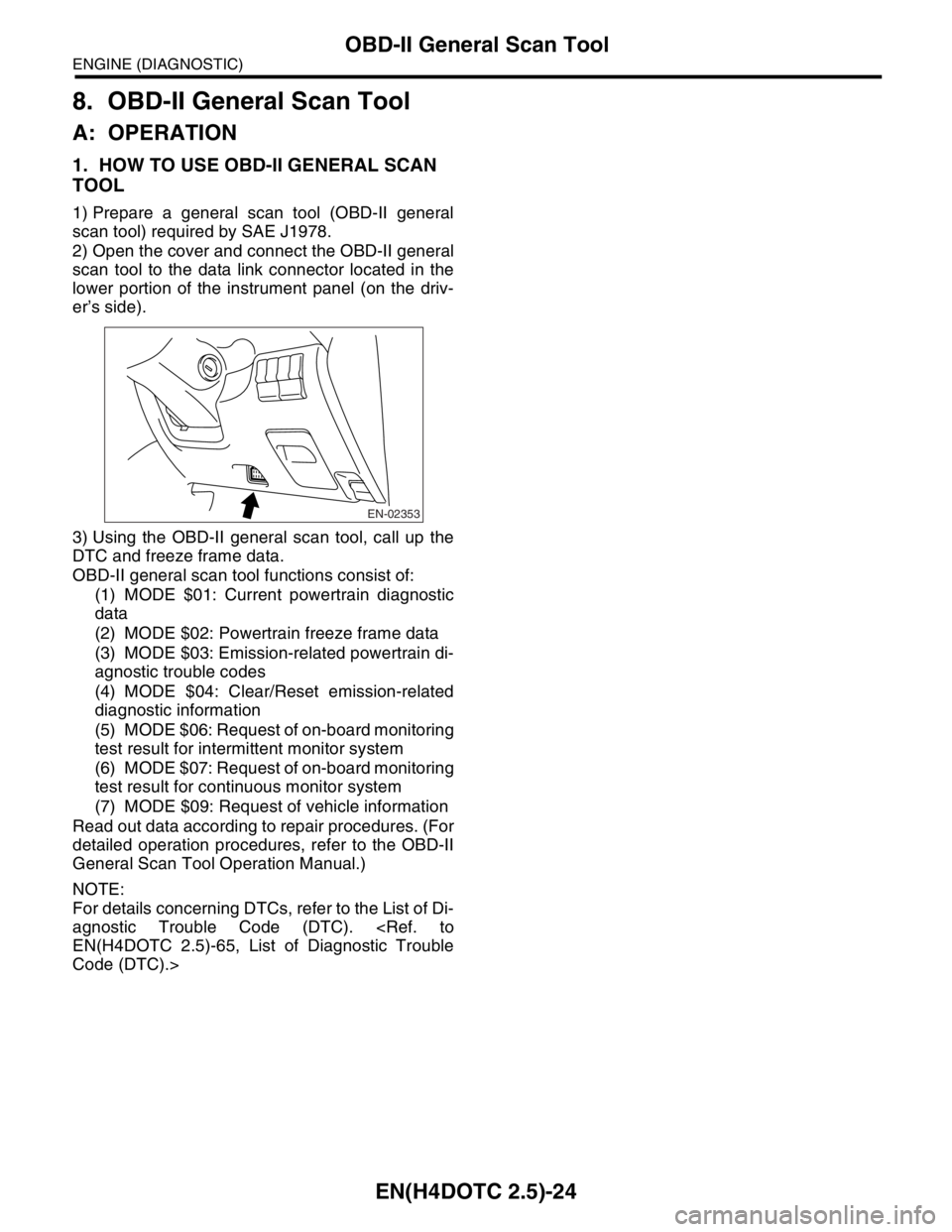
2) Open the cover and connect the OBD-II general
scan tool to the data link connector located in the
lower portion of the instrument panel (on the driv-
er’s side).
3) Using the OBD-II general scan tool, call up the
DTC and freeze frame data.
OBD-II general scan tool functions consist of:
(1) MODE $01: Current powertrain diagnostic
data
(2) MODE $02: Powertrain freeze frame data
(3) MODE $03: Emission-related powertrain di-
agnostic trouble codes
(4) MODE $04: Clear/Reset emission-related
diagnostic information
(5) MODE $06: Request of on-board monitoring
test result for intermittent monitor system
(6) MODE $07: Request of on-board monitoring
test result for continuous monitor system
(7) MODE $09: Request of vehicle information
Read out data according to repair procedures. (For
detailed operation procedures, refer to the OBD-II
General Scan Tool Operation Manual.)
NOTE:
For details concerning DTCs, refer to the List of Di-
agnostic Trouble Code (DTC).
Code (DTC).>
EN-02353
Page 2051 of 2870
EN(H4DOTC 2.5)-27
ENGINE (DIAGNOSTIC)
Subaru Select Monitor
9. Subaru Select Monitor
A: OPERATION
1. HOW TO USE SUBARU SELECT MONI-
TOR
1) Prepare the Subaru Select Monitor kit.
eral Description.>
2) Connect the diagnosis cable to Subaru Select
Monitor.
3) Insert the cartridge to Subaru Select Monitor.
General Description.>
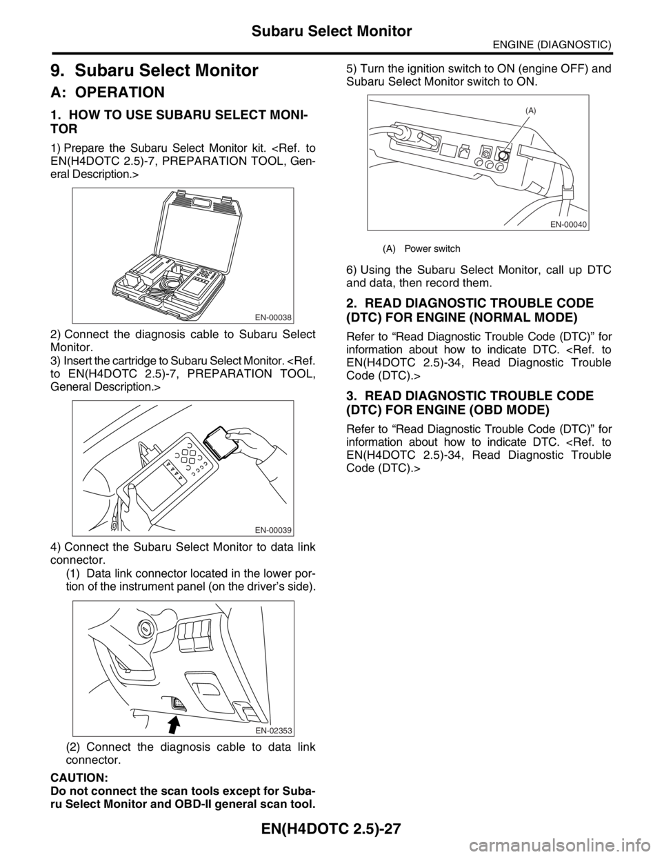
4) Connect the Subaru Select Monitor to data link
connector.
(1) Data link connector located in the lower por-
tion of the instrument panel (on the driver’s side).
(2) Connect the diagnosis cable to data link
connector.
CAUTION:
Do not connect the scan tools except for Suba-
ru Select Monitor and OBD-II general scan tool.5) Turn the ignition switch to ON (engine OFF) and
Subaru Select Monitor switch to ON.
6) Using the Subaru Select Monitor, call up DTC
and data, then record them.
2. READ DIAGNOSTIC TROUBLE CODE
(DTC) FOR ENGINE (NORMAL MODE)
Refer to “Read Diagnostic Trouble Code (DTC)” for
information about how to indicate DTC.
Code (DTC).>
3. READ DIAGNOSTIC TROUBLE CODE
(DTC) FOR ENGINE (OBD MODE)
Refer to “Read Diagnostic Trouble Code (DTC)” for
information about how to indicate DTC.
Code (DTC).>
EN-00038
EN-00039
EN-02353
(A) Power switch
EN-00040
(A)
Page 2061 of 2870
EN(H4DOTC 2.5)-37
ENGINE (DIAGNOSTIC)
Inspection Mode
1. PREPARATION FOR THE INSPECTION
MODE
1) Check battery voltage is more than 12 V and fuel
remains half [20 — 402 (5.3 — 10.6 US gal, 4.4 —
8.8 Imp gal)].
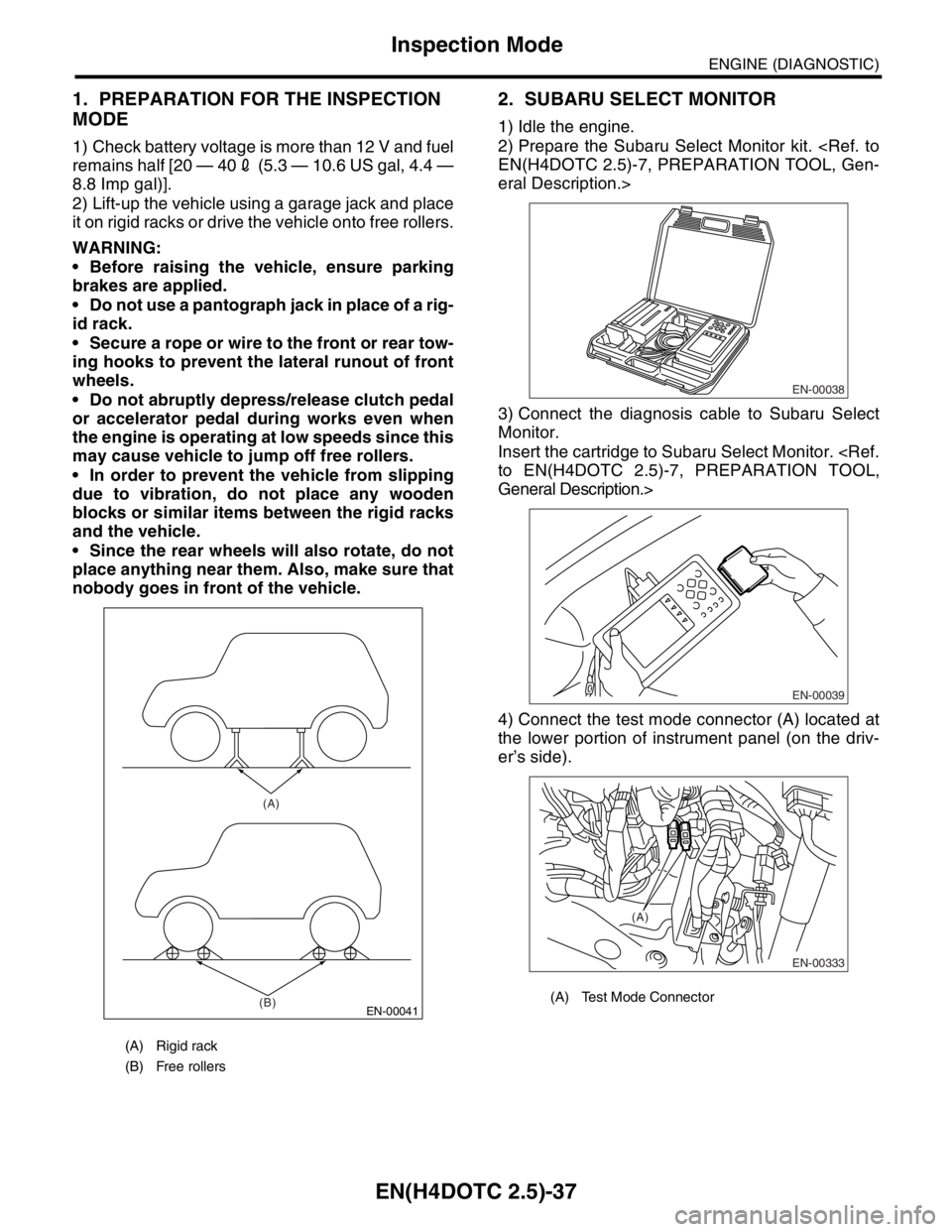
2) Lift-up the vehicle using a garage jack and place
it on rigid racks or drive the vehicle onto free rollers.
WARNING:
Before raising the vehicle, ensure parking
brakes are applied.
Do not use a pantograph jack in place of a rig-
id rack.
Secure a rope or wire to the front or rear tow-
ing hooks to prevent the lateral runout of front
wheels.
Do not abruptly depress/release clutch pedal
or accelerator pedal during works even when
the engine is operating at low speeds since this
may cause vehicle to jump off free rollers.
In order to prevent the vehicle from slipping
due to vibration, do not place any wooden
blocks or similar items between the rigid racks
and the vehicle.
Since the rear wheels will also rotate, do not
place anything near them. Also, make sure that
nobody goes in front of the vehicle.
2. SUBARU SELECT MONITOR
1) Idle the engine.
2) Prepare the Subaru Select Monitor kit.
eral Description.>
3) Connect the diagnosis cable to Subaru Select
Monitor.
Insert the cartridge to Subaru Select Monitor.
General Description.>
4) Connect the test mode connector (A) located at
the lower portion of instrument panel (on the driv-
er’s side).
(A) Rigid rack
(B) Free rollers
EN-00041
(A)
(B)
(A) Test Mode Connector
EN-00038
EN-00039
EN-00333
(A)