2004 SUBARU FORESTER instrument panel
[x] Cancel search: instrument panelPage 1127 of 2870
EN(H4SO)-29
ENGINE (DIAGNOSTIC)
Subaru Select Monitor
10.Subaru Select Monitor
A: OPERATION
1. HOW TO USE SUBARU SELECT MONI-
TOR
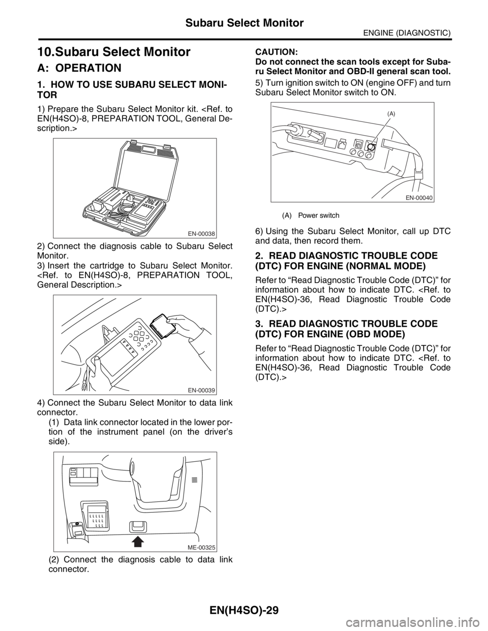
1) Prepare the Subaru Select Monitor kit.
scription.>
2) Connect the diagnosis cable to Subaru Select
Monitor.
3) Insert the cartridge to Subaru Select Monitor.
4) Connect the Subaru Select Monitor to data link
connector.
(1) Data link connector located in the lower por-
tion of the instrument panel (on the driver’s
side).
(2) Connect the diagnosis cable to data link
connector.CAUTION:
Do not connect the scan tools except for Suba-
ru Select Monitor and OBD-II general scan tool.
5) Turn ignition switch to ON (engine OFF) and turn
Subaru Select Monitor switch to ON.
6) Using the Subaru Select Monitor, call up DTC
and data, then record them.
2. READ DIAGNOSTIC TROUBLE CODE
(DTC) FOR ENGINE (NORMAL MODE)
Refer to “Read Diagnostic Trouble Code (DTC)” for
information about how to indicate DTC.
(DTC).>
3. READ DIAGNOSTIC TROUBLE CODE
(DTC) FOR ENGINE (OBD MODE)
Refer to “Read Diagnostic Trouble Code (DTC)” for
information about how to indicate DTC.
(DTC).>
EN-00038
EN-00039
ME-00325
(A) Power switch
EN-00040
(A)
Page 1137 of 2870
EN(H4SO)-39
ENGINE (DIAGNOSTIC)
Inspection Mode
1. PREPARATION FOR THE INSPECTION
MODE
1) Check battery voltage is more than 12 V and fuel
remains half [20 — 402 (5.3 — 10.6 US gal, 4.4 —
8.8 Imp gal)].
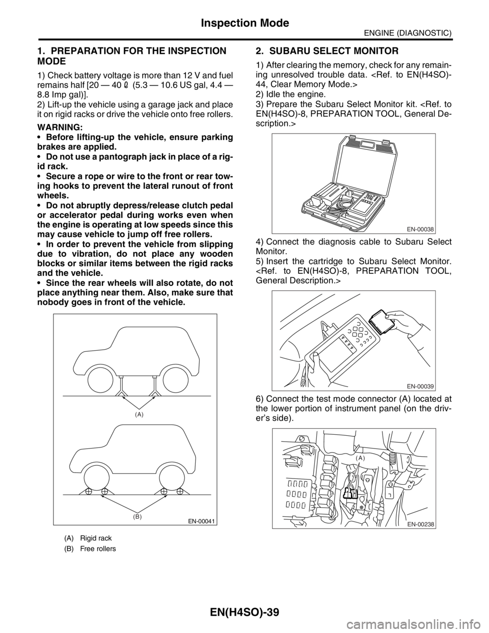
2) Lift-up the vehicle using a garage jack and place
it on rigid racks or drive the vehicle onto free rollers.
WARNING:
Before lifting-up the vehicle, ensure parking
brakes are applied.
Do not use a pantograph jack in place of a rig-
id rack.
Secure a rope or wire to the front or rear tow-
ing hooks to prevent the lateral runout of front
wheels.
Do not abruptly depress/release clutch pedal
or accelerator pedal during works even when
the engine is operating at low speeds since this
may cause vehicle to jump off free rollers.
In order to prevent the vehicle from slipping
due to vibration, do not place any wooden
blocks or similar items between the rigid racks
and the vehicle.
Since the rear wheels will also rotate, do not
place anything near them. Also, make sure that
nobody goes in front of the vehicle.
2. SUBARU SELECT MONITOR
1) After clearing the memory, check for any remain-
ing unresolved trouble data.
2) Idle the engine.
3) Prepare the Subaru Select Monitor kit.
scription.>
4) Connect the diagnosis cable to Subaru Select
Monitor.
5) Insert the cartridge to Subaru Select Monitor.
6) Connect the test mode connector (A) located at
the lower portion of instrument panel (on the driv-
er’s side).
(A) Rigid rack
(B) Free rollers
EN-00041
(A)
(B)
EN-00038
EN-00039
EN-00238
(A)
Page 1138 of 2870
EN(H4SO)-40
ENGINE (DIAGNOSTIC)
Inspection Mode
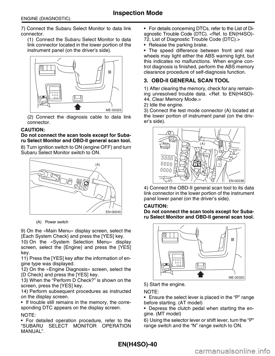
7) Connect the Subaru Select Monitor to data link
connector.
(1) Connect the Subaru Select Monitor to data
link connector located in the lower portion of the
instrument panel (on the driver’s side).
(2) Connect the diagnosis cable to data link
connector.
CAUTION:
Do not connect the scan tools except for Suba-
ru Select Monitor and OBD-II general scan tool.
8) Turn ignition switch to ON (engine OFF) and turn
Subaru Select Monitor switch to ON.
9) On the «Main Menu» display screen, select the
{Each System Check} and press the [YES] key.
10) On the «System Selection Menu» display
screen, select the {Engine} and press the [YES]
key.
11) Press the [YES] key after the information of en-
gine type was displayed.
12) On the «Engine Diagnosis» screen, select the
{D Check} and press the [YES] key.
13) When the “Perform D Check?” is shown on the
screen, press the [YES] key.
14) Perform subsequent procedures as instructed
on the display screen.
If trouble still remains in the memory, the corre-
sponding DTC appears on the display screen.
NOTE:
For detailed operation procedure, refer to the
“SUBARU SELECT MONITOR OPERATION
MANUAL”. For details concerning DTCs, refer to the List of Di-
agnostic Trouble Code (DTC).
Release the parking brake.
The speed difference between front and rear
wheels may light either the ABS warning light, but
this indicates no malfunctions. When engine con-
trol diagnosis is finished, perform the ABS memory
clearance procedure of self-diagnosis function.
3. OBD-II GENERAL SCAN TOOL
1) After clearing the memory, check for any remain-
ing unresolved trouble data.
2) Idle the engine.
3) Connect the test mode connector (A) located at
the lower portion of instrument panel (on the driv-
er’s side).
4) Connect the OBD-II general scan tool to its data
link connector in the lower portion of the instrument
panel lower panel (on the driver’s side).
CAUTION:
Do not connect the scan tools except for Suba-
ru Select Monitor and OBD-II general scan tool.
5) Start the engine.
NOTE:
Ensure the select lever is placed in the “P” range
before starting. (AT model)
Depress the clutch pedal when starting the en-
gine. (MT model)
6) Using the selector lever or shift lever, turn the “P”
range switch and the “N” range switch to ON.
(A) Power switch
ME-00325
EN-00040
(A)
EN-00238
(A)
ME-00325
Page 1268 of 2870

EN(H4SO)-170
ENGINE (DIAGNOSTIC)
Diagnostic Procedure with Diagnostic Trouble Code (DTC)
Step Check Yes No
1 CHECK OUTPUT SIGNAL FROM ECM.
1) Turn the ignition switch to OFF.
2) Connect the test mode connector at the
lower portion of instrument panel (on the
driver’s side).
3) Turn the ignition switch to ON.
4) While operating the purge control solenoid
valve, measure voltage between ECM and
chassis ground.
N
OTE:
Purge control solenoid valve operation can be
executed using Subaru Select Monitor. Refer to
“Compulsory Valve Operation Check Mode” for
procedures.
Connector & terminal
(B134) No. 29 (+) — Chassis ground (
−):Is the voltage 0 — 10 V? Go to step 2.Even if the mal-
function indicator
light illuminates,
the circuit has
returned to a nor-
mal condition at
this time. In this
case, repair poor
contact in ECM
connector.
2 CHECK OUTPUT SIGNAL FROM ECM.
1) Turn the ignition switch to ON.
2) Measure the voltage between ECM and
chassis ground.
Connector & terminal
(B137) No. 29 (+) — Chassis ground (
−):Is the voltage more than 10 V? Go to step 4.Go to step 3.
3 CHECK POOR CONTACT.
Check poor contact in ECM connector. Is there poor contact in ECM
connector?Repair the poor
contact in ECM
connector.Replace the ECM.
Engine Control
Module (ECM).>
4 CHECK HARNESS BETWEEN PURGE CON-
TROL SOLENOID VALVE AND ECM CON-
NECTOR.
1) Turn the ignition switch to OFF.
2) Disconnect the connector from purge con-
trol solenoid valve.
3) Turn the ignition switch to ON.
4) Measure the voltage between ECM and
chassis ground.
Connector & terminal
(B134) No. 29 (+) — Chassis ground (
−):Is the voltage more than 10 V? Repair battery
short circuit in har-
ness between
ECM and purge
control solenoid
valve connector.
After repair,
replace the ECM.
Engine Control
Module (ECM).>Go to step 5.
5 CHECK PURGE CONTROL SOLENOID
VALVE.
1) Turn the ignition switch to OFF.
2) Measure the resistance between purge
control solenoid valve terminals.
Te r m i n a l s
No. 1 — No. 2:Is the resistance less than 1
Ω?Replace the purge
control solenoid
valve
Purge Control
Solenoid Valve.>
and ECM.
Engine Control
Module (ECM).>Go to step 6.
6 CHECK POOR CONTACT.
Check poor contact in ECM connector.Is there poor contact in ECM
connector?Repair the poor
contact in ECM
connector.Replace the ECM.
Engine Control
Module (ECM).>
Page 1300 of 2870

EN(H4SO)-202
ENGINE (DIAGNOSTIC)
Diagnostic Procedure with Diagnostic Trouble Code (DTC)
Step Check Yes No
1 CHECK OUTPUT SIGNAL FROM ECM.
1) Turn the ignition switch to OFF.
2) Connect the test mode connector at the
lower portion of instrument panel (on the
driver’s side).
3) Turn the ignition switch to ON.
4) While operating the radiator fan relay, mea-
sure the voltage between ECM and chassis
ground.
N
OTE:
Radiator fan relay operation can be executed
using Subaru Select Monitor. For procedure,
refer to “Compulsory Valve Operation Check
Mode”.
Connector & terminal
(B134) No. 14 (+) — Chassis ground (
−):Is the voltage 0 — 10 V? Repair the poor
contact in ECM
connector.Go to step 2.
2 CHECK GROUND SHORT CIRCUIT IN RADI-
ATOR MAIN FAN RELAY CONTROL CIR-
CUIT.
1) Turn the ignition switch to OFF.
2) Disconnect the connector from ECM.
3) Measure the resistance of harness
between ECM connector and chassis ground.
Connector & terminal
(B134) No. 14 — Chassis ground:Is the resistance less than 10
Ω?Repair the ground
short circuit in
radiator main fan
relay control cir-
cuit.Go to step 3.
3 CHECK POWER SUPPLY FOR RELAY.
1) Remove the main fan relay from A/C relay
holder.
2) Turn the ignition switch to ON.
3) Measure the voltage between fuse and
relay box (F/B) connector and chassis ground.
Connector & terminal
(F27) No. 34 (+) — Chassis ground (
−):Is the voltage more than 10 V? Go to step 4.Repair open circuit
in harness
between ignition
switch and fuse
and relay box (F/B)
connector.
4 CHECK MAIN FAN RELAY.
1) Turn the ignition switch to OFF.
2) Measure the resistance between main fan
relay terminals.
Te r m i n a l s
No. 32 — No. 34:Is the resistance 87 — 107 Ω? Go to step 5.Replace the main
fan relay.
5 CHECK OPEN CIRCUIT IN MAIN FAN RE-
LAY CONTROL CIRCUIT.
Measure the resistance of harness between
ECM and main fan relay connector.
Connector & terminal
(B134) No. 14 — (F27) No. 32:Is the resistance less than 1
Ω?Go to step 6.Repair harness
and connector.
NOTE:
In this case repair
the following:
Open circuit in
harness between
ECM and main fan
relay connector
Poor contact in
coupling connector
6 CHECK POOR CONTACT.
Check poor contact in ECM or main fan relay
connector. Is there poor contact in ECM or
main fan relay connector?Repair the poor
contact in ECM or
main fan relay con-
nector.Contact the SUB-
ARU dealer.
Page 1303 of 2870

EN(H4SO)-205
ENGINE (DIAGNOSTIC)
Diagnostic Procedure with Diagnostic Trouble Code (DTC)
Step Check Yes No
1 CHECK OUTPUT SIGNAL FROM ECM.
1) Turn the ignition switch to OFF.
2) Connect the test mode connector at the
lower portion of instrument panel (on the
driver’s side).
3) Turn the ignition switch to ON.
4) While operating the radiator fan relay, mea-
sure the voltage between ECM and chassis
ground.
N
OTE:
Radiator fan relay operation can be executed
using Subaru Select Monitor. For procedure,
refer to “Compulsory Valve Operation Check
Mode”.
Connector & terminal
(B134) No. 14 (+) — Chassis ground (
−):
(B134) No. 13 (+) — Chassis ground (
−):Is the voltage 0 — 10 V? Even if the mal-
function indicator
light illuminates,
the circuit has
returned to a nor-
mal condition at
this time. In this
case, repair poor
contact in ECM
connector.Go to step 2.
2 CHECK SHORT CIRCUIT IN RADIATOR FAN
RELAY CONTROL CIRCUIT.
1) Turn the ignition switch to OFF.
2) Remove the main fan relay and sub fan
relay. (model with A/C)
3) Disconnect the test mode connectors
4) Turn the ignition switch to ON.
5) Measure the voltage between ECM and
chassis ground.
Connector & terminal
(B134) No. 14 (+) — Chassis ground (
−):
(B134) No. 13 (+) — Chassis ground (
−):Is the voltage more than 10 V? Repair battery
short circuit in
radiator fan relay
control circuit.
After repair,
replace the ECM.
Engine Control
Module (ECM).>Go to step 3.
3 CHECK MAIN FAN RELAY.
1) Turn the ignition switch to OFF.
2) Remove the main fan relay.
3) Measure the resistance between main fan
relay terminals.
Te r m i n a l s
No. 30 — No. 31:Is the resistance less than 1
Ω?Replace the main
fan relay and
ECM.
Engine Control
Module (ECM).>Go to step 4.
4 CHECK SUB FAN RELAY.
1) Remove the sub fan relay.
2) Measure the resistance between sub fan
relay terminals.
Te r m i n a l s
No. 28 — No. 29:Is the resistance less than 1
Ω?Replace the sub
fan relay and
ECM.
Engine Control
Module (ECM).>Go to step 5.
5 CHECK POOR CONTACT.
Check poor contact in ECM connector.Is there poor contact in ECM
connector?Repair the poor
contact in ECM
connector.Replace the ECM.
Engine Control
Module (ECM).>
Page 1660 of 2870
EN(H4DOTC)-30
ENGINE (DIAGNOSTIC)
OBD-II General Scan Tool
9. OBD-II General Scan Tool
A: OPERATION
1. HOW TO USE OBD-II GENERAL SCAN
TOOL
1) Prepare a general scan tool (OBD-II general
scan tool) required by SAE J1978.
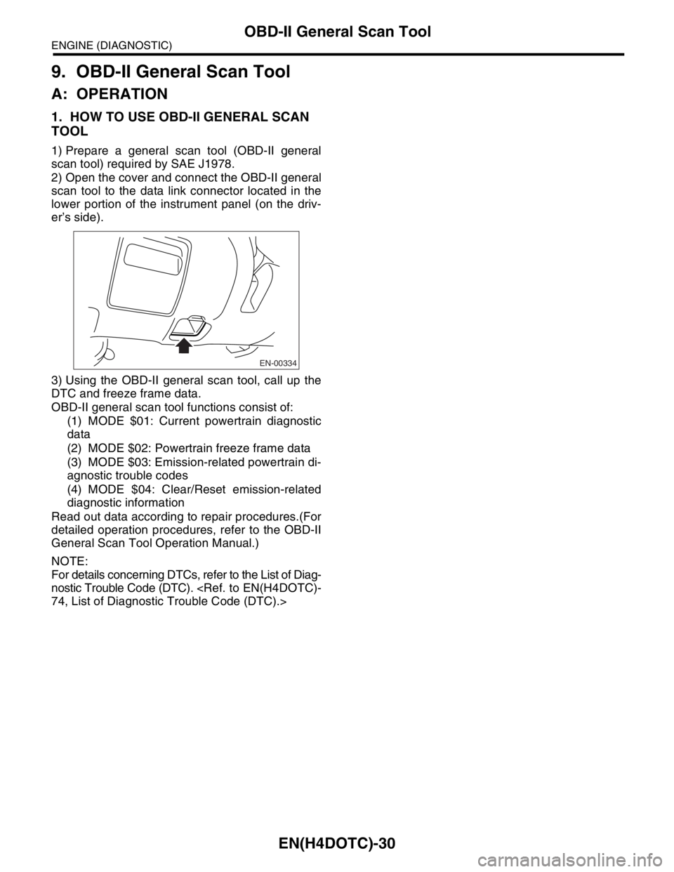
2) Open the cover and connect the OBD-II general
scan tool to the data link connector located in the
lower portion of the instrument panel (on the driv-
er’s side).
3) Using the OBD-II general scan tool, call up the
DTC and freeze frame data.
OBD-II general scan tool functions consist of:
(1) MODE $01: Current powertrain diagnostic
data
(2) MODE $02: Powertrain freeze frame data
(3) MODE $03: Emission-related powertrain di-
agnostic trouble codes
(4) MODE $04: Clear/Reset emission-related
diagnostic information
Read out data according to repair procedures.(For
detailed operation procedures, refer to the OBD-II
General Scan Tool Operation Manual.)
NOTE:
For details concerning DTCs, refer to the List of Diag-
nostic Trouble Code (DTC).
EN-00334
Page 1663 of 2870
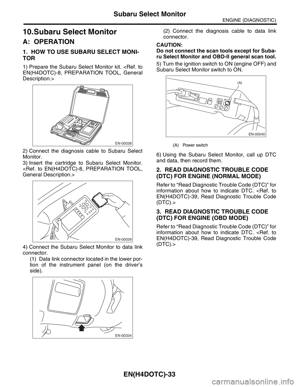
EN(H4DOTC)-33
ENGINE (DIAGNOSTIC)
Subaru Select Monitor
10.Subaru Select Monitor
A: OPERATION
1. HOW TO USE SUBARU SELECT MONI-
TOR
1) Prepare the Subaru Select Monitor kit.
Description.>
2) Connect the diagnosis cable to Subaru Select
Monitor.
3) Insert the cartridge to Subaru Select Monitor.
4) Connect the Subaru Select Monitor to data link
connector.
(1) Data link connector located in the lower por-
tion of the instrument panel (on the driver’s
side).(2) Connect the diagnosis cable to data link
connector.
CAUTION:
Do not connect the scan tools except for Suba-
ru Select Monitor and OBD-II general scan tool.
5) Turn the ignition switch to ON (engine OFF) and
Subaru Select Monitor switch to ON.
6) Using the Subaru Select Monitor, call up DTC
and data, then record them.
2. READ DIAGNOSTIC TROUBLE CODE
(DTC) FOR ENGINE (NORMAL MODE)
Refer to “Read Diagnostic Trouble Code (DTC)” for
information about how to indicate DTC.
(DTC).>
3. READ DIAGNOSTIC TROUBLE CODE
(DTC) FOR ENGINE (OBD MODE)
Refer to “Read Diagnostic Trouble Code (DTC)” for
information about how to indicate DTC.
(DTC).>
EN-00038
EN-00039
EN-00334
(A) Power switch
EN-00040
(A)