Page 516 of 2870
EI-40
EXTERIOR/INTERIOR TRIM
Instrument Panel Assembly
16.Instrument Panel Assembly
A: REMOVAL
CAUTION:
All airbag system wiring harness and connec-
tors are colored yellow. Do not use electrical test
equipment on these circuits.
Be careful not to damage the airbag system
harness when servicing the instrument panel.
1. REMOVAL OF INSTRUMENT PANEL
ONLY
1) Disconnect the ground cable from battery.
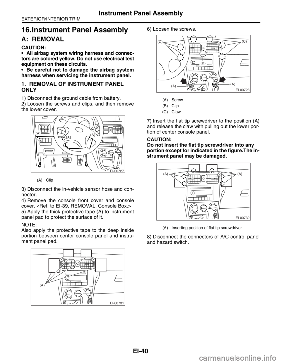
2) Loosen the screws and clips, and then remove
the lower cover.
3) Disconnect the in-vehicle sensor hose and con-
nector.
4) Remove the console front cover and console
cover.
5) Apply the thick protective tape (A) to instrument
panel pad to protect the surface of it.
NOTE:
Also apply the protective tape to the deep inside
portion between center console panel and instru-
ment panel pad.6) Loosen the screws.
7) Insert the flat tip screwdriver to the position (A)
and release the claw with pulling out the lower por-
tion of center console panel.
CAUTION:
Do not insert the flat tip screwdriver into any
portion except for indicated in the figure.The in-
strument panel may be damaged.
8) Disconnect the connectors of A/C control panel
and hazard switch.
(A) Clip
EI-00727
(A)
(A)(A)
EI-00731
(A)
(A) Screw
(B) Clip
(C) Claw
(A) Inserting position of flat tip screwdriver
EI-00728
(C)
(A)(A)(C)
(B)
EI-00732
(A) (A)
Page 517 of 2870
EI-41
EXTERIOR/INTERIOR TRIM
Instrument Panel Assembly
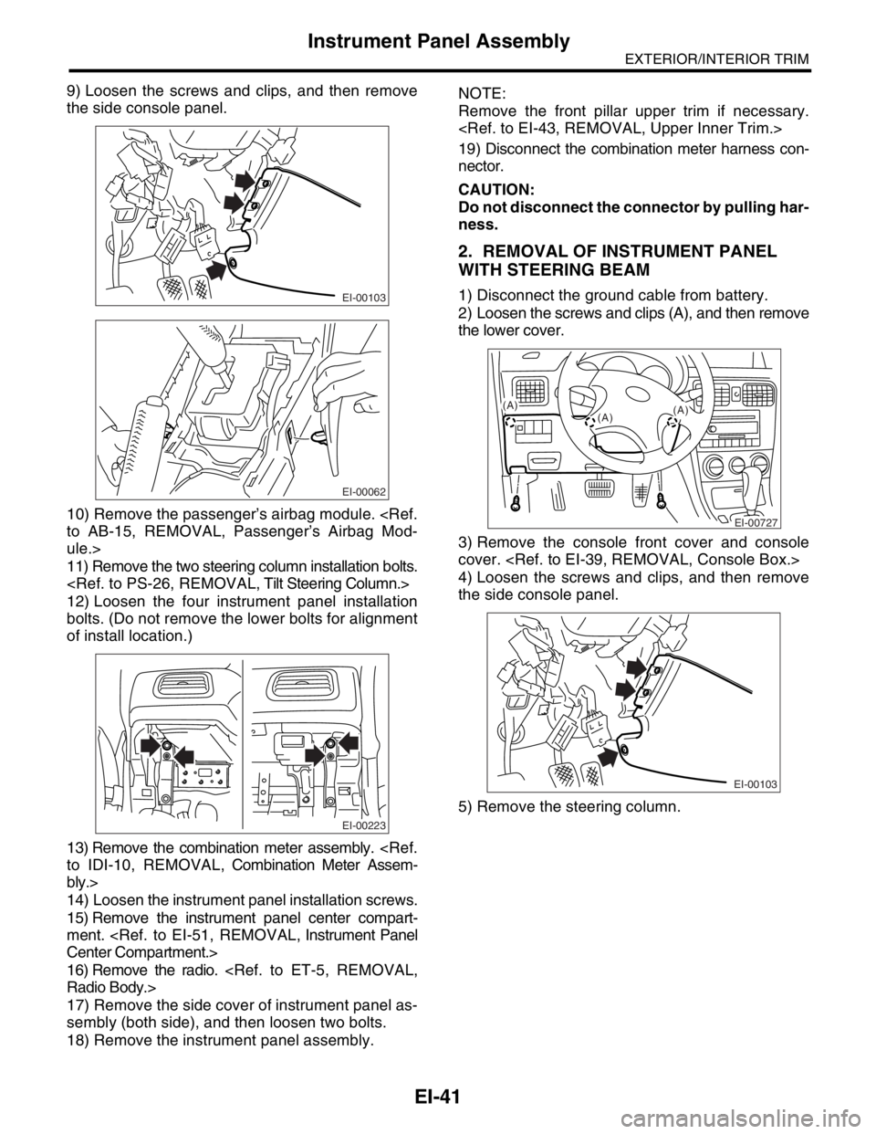
9) Loosen the screws and clips, and then remove
the side console panel.
10) Remove the passenger’s airbag module.
to AB-15, REMOVAL, Passenger’s Airbag Mod-
ule.>
11) Remove the two steering column installation bolts.
12) Loosen the four instrument panel installation
bolts. (Do not remove the lower bolts for alignment
of install location.)
13) Remove the combination meter assembly.
to IDI-10, REMOVAL, Combination Meter Assem-
bly.>
14) Loosen the instrument panel installation screws.
15) Remove the instrument panel center compart-
ment.
Center Compartment.>
16) Remove the radio.
Radio Body.>
17) Remove the side cover of instrument panel as-
sembly (both side), and then loosen two bolts.
18) Remove the instrument panel assembly.NOTE:
Remove the front pillar upper trim if necessary.
19) Disconnect the combination meter harness con-
nector.
CAUTION:
Do not disconnect the connector by pulling har-
ness.
2. REMOVAL OF INSTRUMENT PANEL
WITH STEERING BEAM
1) Disconnect the ground cable from battery.
2) Loosen the screws and clips (A), and then remove
the lower cover.
3) Remove the console front cover and console
cover.
4) Loosen the screws and clips, and then remove
the side console panel.
5) Remove the steering column.EI-00103
EI-00062
EI-00223
EI-00727
(A)
(A)(A)
EI-00103
Page 518 of 2870
EI-42
EXTERIOR/INTERIOR TRIM
Instrument Panel Assembly
6) Loosen the four instrument panel installation bolts.
7) Remove the driver’s and passenger’s airbag mod-
ule.
Module.>
Airbag Module.>
8) Loosen the steering beam installation bolts.
9) Loosen the brake pedal installation bolts.
to BR-50, REMOVAL, Brake Pedal.>
10) Remove two clips from the edge of instrument
panel assembly.
11) Remove the instrument panel assembly.
CAUTION:
Do not disconnect the connector by pulling har-
ness.
NOTE:
If necessary, make matching marks for easy re-
assembly.
When storing the removed instrument panel, place it
standing up on the floor.B: INSTALLATION
Install in the reverse order of removal.
CAUTION:
Be careful not to snag the harness.
Make sure to connect the harness connector.
NOTE:
When setting the instrument panel into position, push
the hook into grommet (A) on the body panel.
EI-00066
EI-00068
EI-00069
(A)
(A)(A)
Page 527 of 2870
EI-51
EXTERIOR/INTERIOR TRIM
Instrument Panel Center Compartment
25.Instrument Panel Center
Compartment
A: REMOVAL
1) Disconnect the ground cable from battery.
2) Insert a flat tip screwdriver, and then pry up to re-
move the clips.
3) Remove the instrument panel center compartment
from instrument panel.
4) Disconnect the connector from clock.
B: INSTALLATION
Install in the reverse order of removal.
(A) Clip
EI-00081: A
Page 529 of 2870
FUJI HEAVY INDUSTRIES LTD. G8080GE7
2004 FORESTER SERVICE MANUAL QUICK REFERENCE INDEX
BODY SECTION
This service manual has been prepared
to provide SUBARU service personnel
with the necessary information and data
for the correct maintenance and repair
of SUBARU vehicles.
This manual includes the procedures
for maintenance, disassembling, reas-
sembling, inspection and adjustment of
components and diagnostics for guid-
ance of experienced mechanics.
Please peruse and utilize this manual
fully to ensure complete repair work for
satisfying our customers by keeping
their vehicle in optimum condition.
When replacement of parts during
repair work is needed, be sure to use
SUBARU genuine parts.
All information, illustration and specifi-
cations contained in this manual are
based on the latest product information
available at the time of publication
approval.HVAC SYSTEM
(HEATER, VENTILATOR AND A/C)AC
HVAC SYSTEM (AUTO A/C)
(DIAGNOSTIC)AC
AIRBAG SYSTEM AB
AIRBAG SYSTEM (DIAGNOSTIC) AB
SEAT BELT SYSTEM SB
LIGHTING SYSTEM LI
WIPER AND WASHER SYSTEM WW
ENTERTAINMENT ET
COMMUNICATION SYSTEM COM
GLASS/WINDOW/MIRROR GW
BODY STRUCTURE BS
INSTRUMENTATION/DRIVER INFO IDI
SEAT SE
SECURITY AND LOCK SL
SUNROOF/T-TOP/CONVERTIBLE TOP
(SUNROOF)SR
EXTERIOR/INTERIOR TRIM EI
EXTERIOR BODY PANEL EB
Page 551 of 2870
FUJI HEAVY INDUSTRIES LTD. G8080GE7
2004 FORESTER SERVICE MANUAL QUICK REFERENCE INDEX
BODY SECTION
This service manual has been prepared
to provide SUBARU service personnel
with the necessary information and data
for the correct maintenance and repair
of SUBARU vehicles.
This manual includes the procedures
for maintenance, disassembling, reas-
sembling, inspection and adjustment of
components and diagnostics for guid-
ance of experienced mechanics.
Please peruse and utilize this manual
fully to ensure complete repair work for
satisfying our customers by keeping
their vehicle in optimum condition.
When replacement of parts during
repair work is needed, be sure to use
SUBARU genuine parts.
All information, illustration and specifi-
cations contained in this manual are
based on the latest product information
available at the time of publication
approval.HVAC SYSTEM
(HEATER, VENTILATOR AND A/C)AC
HVAC SYSTEM (AUTO A/C)
(DIAGNOSTIC)AC
AIRBAG SYSTEM AB
AIRBAG SYSTEM (DIAGNOSTIC) AB
SEAT BELT SYSTEM SB
LIGHTING SYSTEM LI
WIPER AND WASHER SYSTEM WW
ENTERTAINMENT ET
COMMUNICATION SYSTEM COM
GLASS/WINDOW/MIRROR GW
BODY STRUCTURE BS
INSTRUMENTATION/DRIVER INFO IDI
SEAT SE
SECURITY AND LOCK SL
SUNROOF/T-TOP/CONVERTIBLE TOP
(SUNROOF)SR
EXTERIOR/INTERIOR TRIM EI
EXTERIOR BODY PANEL EB
Page 560 of 2870
CC-8
CRUISE CONTROL SYSTEM
Cruise Control Main Switch
4. Cruise Control Main Switch
A: REMOVAL
1) Disconnect the ground cable from battery.
2) Remove the screws and clip from instrument
panel lower cover.
3) Remove the instrument panel lower cover.
4) Disconnect the connector from cruise control
main switch.
5) Remove the main switch by pushing it outward.
For Europe model
For Australia model
B: INSTALLATION
Install in the reverse order of removal.
C: INSPECTION
Measure the cruise control main switch resistance.
If NG, replace the cruise control main switch.
CC-00014
CC-00015
CC-00071
CC-00072
Switch position Terminal No. Standard
OFF (released)LHD, RHD (For
Europe) model : 1
and 2More than 1 MΩ
ON (depressed)RHD (Except for
Europe) model : 3
and 5Less than 1 Ω
CC-00073
1 2
64
53
Page 567 of 2870
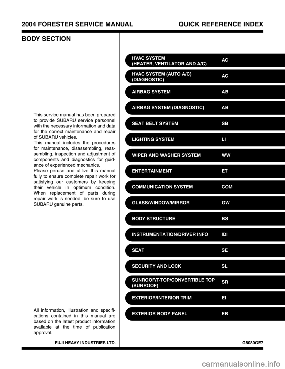
FUJI HEAVY INDUSTRIES LTD. G8080GE7
2004 FORESTER SERVICE MANUAL QUICK REFERENCE INDEX
BODY SECTION
This service manual has been prepared
to provide SUBARU service personnel
with the necessary information and data
for the correct maintenance and repair
of SUBARU vehicles.
This manual includes the procedures
for maintenance, disassembling, reas-
sembling, inspection and adjustment of
components and diagnostics for guid-
ance of experienced mechanics.
Please peruse and utilize this manual
fully to ensure complete repair work for
satisfying our customers by keeping
their vehicle in optimum condition.
When replacement of parts during
repair work is needed, be sure to use
SUBARU genuine parts.
All information, illustration and specifi-
cations contained in this manual are
based on the latest product information
available at the time of publication
approval.HVAC SYSTEM
(HEATER, VENTILATOR AND A/C)AC
HVAC SYSTEM (AUTO A/C)
(DIAGNOSTIC)AC
AIRBAG SYSTEM AB
AIRBAG SYSTEM (DIAGNOSTIC) AB
SEAT BELT SYSTEM SB
LIGHTING SYSTEM LI
WIPER AND WASHER SYSTEM WW
ENTERTAINMENT ET
COMMUNICATION SYSTEM COM
GLASS/WINDOW/MIRROR GW
BODY STRUCTURE BS
INSTRUMENTATION/DRIVER INFO IDI
SEAT SE
SECURITY AND LOCK SL
SUNROOF/T-TOP/CONVERTIBLE TOP
(SUNROOF)SR
EXTERIOR/INTERIOR TRIM EI
EXTERIOR BODY PANEL EB