2004 SUBARU FORESTER instrument panel
[x] Cancel search: instrument panelPage 2062 of 2870
EN(H4DOTC 2.5)-38
ENGINE (DIAGNOSTIC)
Inspection Mode
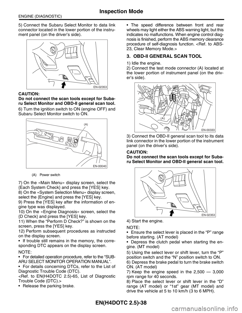
5) Connect the Subaru Select Monitor to data link
connector located in the lower portion of the instru-
ment panel (on the driver’s side).
CAUTION:
Do not connect the scan tools except for Suba-
ru Select Monitor and OBD-II general scan tool.
6) Turn the ignition switch to ON (engine OFF) and
Subaru Select Monitor switch to ON.
7) On the «Main Menu» display screen, select the
{Each System Check} and press the [YES] key.
8) On the «System Selection Menu» display screen,
select the {Engine} and press the [YES] key.
9) Press the [YES] key after the information of en-
gine type was displayed.
10) On the «Engine Diagnosis» screen, select the
{D Check} and press the [YES] key.
11) When the “Perform D Check?” is shown on the
screen, press the [YES] key.
12) Perform subsequent procedures as instructed
on the display screen.
If trouble still remains in the memory, the corre-
sponding DTC appears on the display screen.
NOTE:
For detailed operation procedure, refer to the “SUB-
ARU SELECT MONITOR OPERATION MANUAL”.
For details concerning DTCs, refer to the List of
Diagnostic Trouble Code (DTC).
Release the parking brake. The speed difference between front and rear
wheels may light either the ABS warning light, but this
indicates no malfunctions. When engine control diag-
nosis is finished, perform the ABS memory clearance
procedure of self-diagnosis function.
3. OBD-II GENERAL SCAN TOOL
1) Idle the engine.
2) Connect the test mode connector (A) located at
the lower portion of instrument panel (on the driv-
er’s side).
3) Connect the OBD-II general scan tool to its data
link connector in the lower portion of the instrument
panel (on the driver’s side).
CAUTION:
Do not connect the scan tools except for Suba-
ru Select Monitor and OBD-II general scan tool.
4) Start the engine.
NOTE:
Ensure the select lever is placed in the “P” range
before starting. (AT model)
Depress the clutch pedal when starting the en-
gine. (MT model)
5) Using the select lever or shift lever, turn the “P”
position switch and the “N” position switch to ON.
6) Depress the brake pedal to turn the brake switch
ON. (AT model)
7) Keep the engine speed in the 2,500 — 3,000
rpm range for 40 seconds.
8) Place the select lever or shift lever in the “D”
range (AT model) or “1st” gear (MT model) and
drive the vehicle at 5 to 10 km/h (3 to 6 MPH).
(A) Power switch
EN-02353
EN-00040
(A)
EN-00333
(A)
EN-02353
Page 2067 of 2870
EN(H4DOTC 2.5)-43
ENGINE (DIAGNOSTIC)
Compulsory Valve Operation Check Mode
14.Compulsory Valve Operation
Check Mode
A: OPERATION
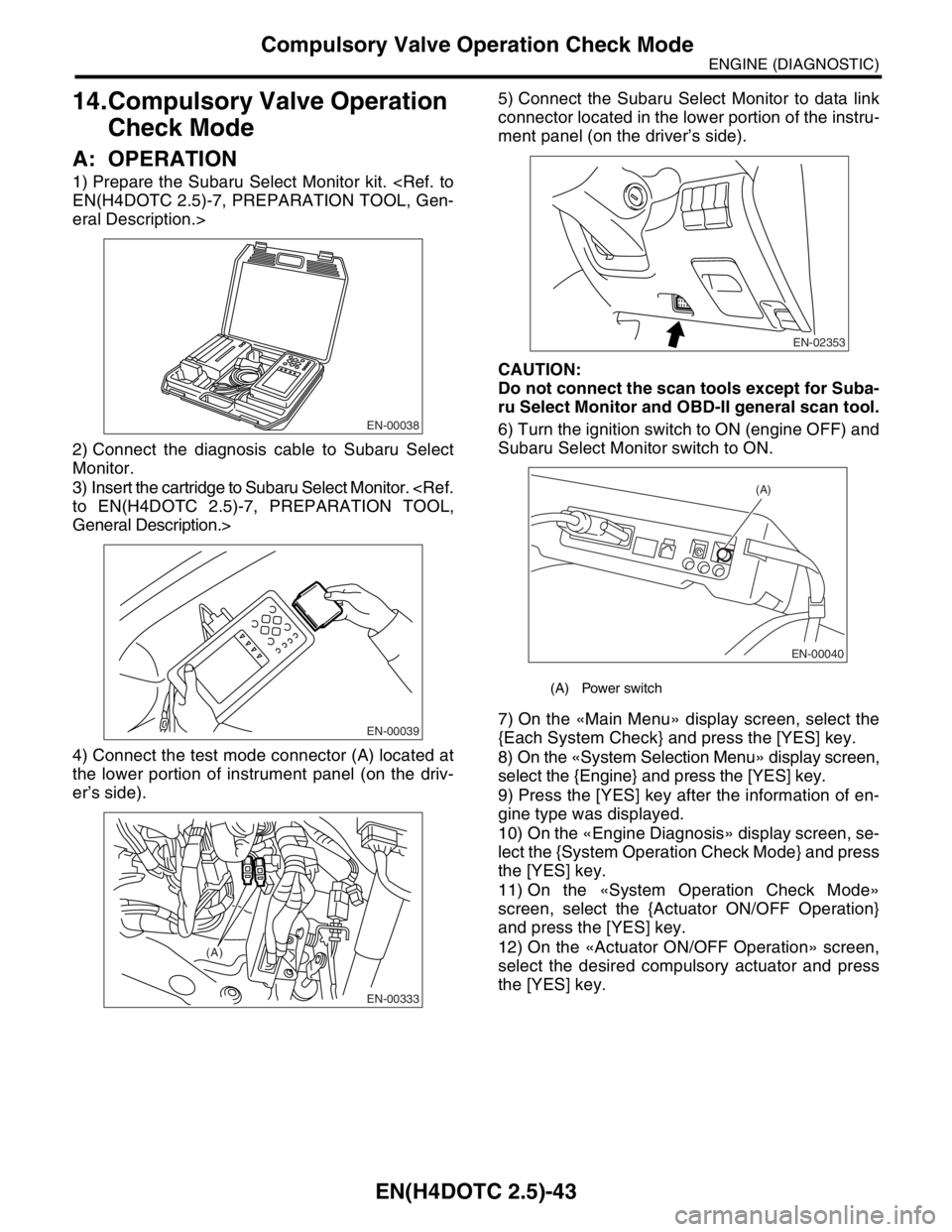
1) Prepare the Subaru Select Monitor kit.
eral Description.>
2) Connect the diagnosis cable to Subaru Select
Monitor.
3) Insert the cartridge to Subaru Select Monitor.
General Description.>
4) Connect the test mode connector (A) located at
the lower portion of instrument panel (on the driv-
er’s side).5) Connect the Subaru Select Monitor to data link
connector located in the lower portion of the instru-
ment panel (on the driver’s side).
CAUTION:
Do not connect the scan tools except for Suba-
ru Select Monitor and OBD-II general scan tool.
6) Turn the ignition switch to ON (engine OFF) and
Subaru Select Monitor switch to ON.
7) On the «Main Menu» display screen, select the
{Each System Check} and press the [YES] key.
8) On the «System Selection Menu» display screen,
select the {Engine} and press the [YES] key.
9) Press the [YES] key after the information of en-
gine type was displayed.
10) On the «Engine Diagnosis» display screen, se-
lect the {System Operation Check Mode} and press
the [YES] key.
11) On the «System Operation Check Mode»
screen, select the {Actuator ON/OFF Operation}
and press the [YES] key.
12) On the «Actuator ON/OFF Operation» screen,
select the desired compulsory actuator and press
the [YES] key.
EN-00038
EN-00039
EN-00333
(A)
(A) Power switch
EN-02353
EN-00040
(A)
Page 2168 of 2870

EN(H4DOTC 2.5)-144
ENGINE (DIAGNOSTIC)
Diagnostic Procedure with Diagnostic Trouble Code (DTC)
Step Check Yes No
1 CHECK OUTPUT SIGNAL FROM ECM.
1) Turn the ignition switch to OFF.
2) Connect the test mode connector at the lower
portion of instrument panel (on the driver’s side).
3) Turn the ignition switch to ON.
4) While operating the purge control solenoid
valve, measure voltage between ECM and
chassis ground.
N
OTE:
Purge control solenoid valve operation can be
executed using Subaru Select Monitor. For the
procedure, refer to “Compulsory Valve Opera-
tion Check Mode”.
Mode.>
Connector & terminal
(B134) No. 14 (+) — Chassis ground (
−):Is the voltage 0 — 13 V? Go to step 2.Even if the mal-
function indicator
light illuminates,
the circuit has
returned to a nor-
mal condition at
this time. In this
case, repair poor
contact in ECM
connector.
2 CHECK OUTPUT SIGNAL FROM ECM.
1) Turn the ignition switch to ON.
2) Measure the voltage between ECM and
chassis ground.
Connector & terminal
(B134) No. 14 (+) — Chassis ground (
−):Is the voltage more than 10 V? Go to step 4.Go to step 3.
3 CHECK POOR CONTACT.
Check poor contact in ECM connector.Is there poor contact in ECM
connector?Repair the poor
contact in ECM
connector.Replace the ECM.
41, Engine Con-
trol Module
(ECM).>
4 CHECK HARNESS BETWEEN PURGE CON-
TROL SOLENOID VALVE AND ECM CON-
NECTOR.
1) Turn the ignition switch to OFF.
2) Disconnect the connector from purge con-
trol solenoid valve.
3) Turn the ignition switch to ON.
4) Measure the voltage between ECM and
chassis ground.
Connector & terminal
(B134) No. 14 (+) — Chassis ground (
−):Is the voltage more than 10 V? Repair battery
short circuit in har-
ness between
ECM and purge
control solenoid
valve connector.
After repair,
replace the ECM.
41, Engine Con-
trol Module
(ECM).>Go to step 5.
5 CHECK PURGE CONTROL SOLENOID
VALVE.
1) Turn the ignition switch to OFF.
2) Measure the resistance between purge
control solenoid valve terminals.
Te r m i n a l s
No. 1 — No. 2:Is the resistance less than 1
Ω?Replace the purge
control solenoid
valve and ECM.
Purge Control
Solenoid Valve.>
41, Engine Con-
trol Module
(ECM).>Go to step 6.
6 CHECK POOR CONTACT.
Check poor contact in ECM connector.Is there poor contact in ECM
connector?Repair the poor
contact in ECM
connector.Replace the ECM.
41, Engine Con-
trol Module
(ECM).>
Page 2476 of 2870
4AT(H4SO)-17
AUTOMATIC TRANSMISSION (DIAGNOSTIC)
Subaru Select Monitor
6. Subaru Select Monitor
A: OPERATION
1. READ DIAGNOSTIC TROUBLE CODE
(DTC)
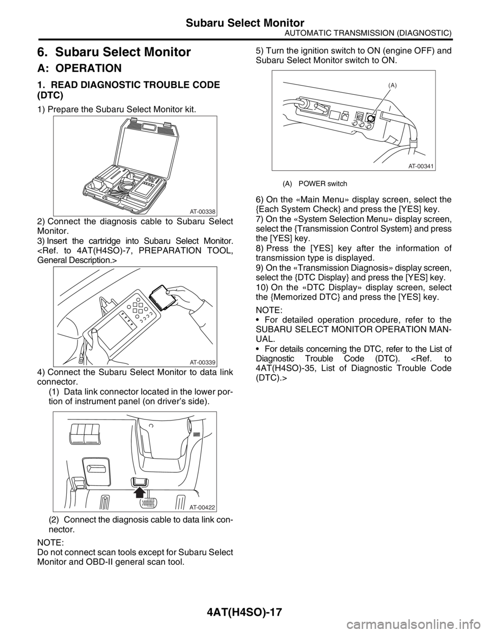
1) Prepare the Subaru Select Monitor kit.
2) Connect the diagnosis cable to Subaru Select
Monitor.
3) Insert the cartridge into Subaru Select Monitor.
4) Connect the Subaru Select Monitor to data link
connector.
(1) Data link connector located in the lower por-
tion of instrument panel (on driver’s side).
(2) Connect the diagnosis cable to data link con-
nector.
NOTE:
Do not connect scan tools except for Subaru Select
Monitor and OBD-II general scan tool.5) Turn the ignition switch to ON (engine OFF) and
Subaru Select Monitor switch to ON.
6) On the «Main Menu» display screen, select the
{Each System Check} and press the [YES] key.
7) On the «System Selection Menu» display screen,
select the {Transmission Control System} and press
the [YES] key.
8) Press the [YES] key after the information of
transmission type is displayed.
9) On the «Transmission Diagnosis» display screen,
select the {DTC Display} and press the [YES] key.
10) On the «DTC Display» display screen, select
the {Memorized DTC} and press the [YES] key.
NOTE:
For detailed operation procedure, refer to the
SUBARU SELECT MONITOR OPERATION MAN-
UAL.
For details concerning the DTC, refer to the List of
Diagnostic Trouble Code (DTC).
(DTC).>
AT-00338
AT-00339
AT-00422
(A) POWER switch
(A)
AT-00341
Page 2591 of 2870
4AT(H4DOTC)-15
AUTOMATIC TRANSMISSION (DIAGNOSTIC)
Subaru Select Monitor
6. Subaru Select Monitor
A: OPERATION
1. READ DIAGNOSTIC TROUBLE CODE
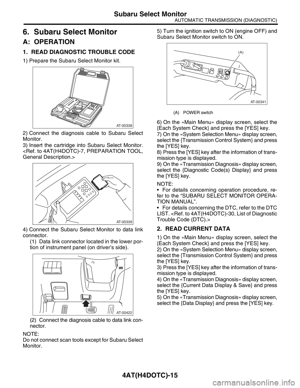
1) Prepare the Subaru Select Monitor kit.
2) Connect the diagnosis cable to Subaru Select
Monitor.
3) Insert the cartridge into Subaru Select Monitor.
4) Connect the Subaru Select Monitor to data link
connector.
(1) Data link connector located in the lower por-
tion of instrument panel (on driver’s side).
(2) Connect the diagnosis cable to data link con-
nector.
NOTE:
Do not connect scan tools except for Subaru Select
Monitor.5) Turn the ignition switch to ON (engine OFF) and
Subaru Select Monitor switch to ON.
6) On the «Main Menu» display screen, select the
{Each System Check} and press the [YES] key.
7) On the «System Selection Menu» display screen,
select the {Transmission Control System} and press
the [YES] key.
8) Press the [YES] key after the information of trans-
mission type is displayed.
9) On the «Transmission Diagnosis» display screen,
select the {Diagnostic Code(s) Display} and press
the [YES] key.
NOTE:
For details concerning operation procedure, re-
fer to the “SUBARU SELECT MONITOR OPERA-
TION MANUAL”.
For details concerning the DTC, refer to the DTC
LIST.
2. READ CURRENT DATA
1) On the «Main Menu» display screen, select the
{Each System Check} and press the [YES] key.
2) On the «System Selection Menu» display screen,
select the {Transmission Control System} and press
the [YES] key.
3) Press the [YES] key after the information of trans-
mission type is displayed.
4) On the «Transmission Diagnosis» display screen,
select the {Current Data Display & Save} and press
the [YES] key.
5) On the «Transmission Diagnosis» display screen,
select the {Data Display} and press the [YES] key.
AT-00338
AT-00339
AT-00422
(A) POWER switch
(A)
AT-00341
Page 2861 of 2870
CL-35
CLUTCH SYSTEM
Clutch Pedal
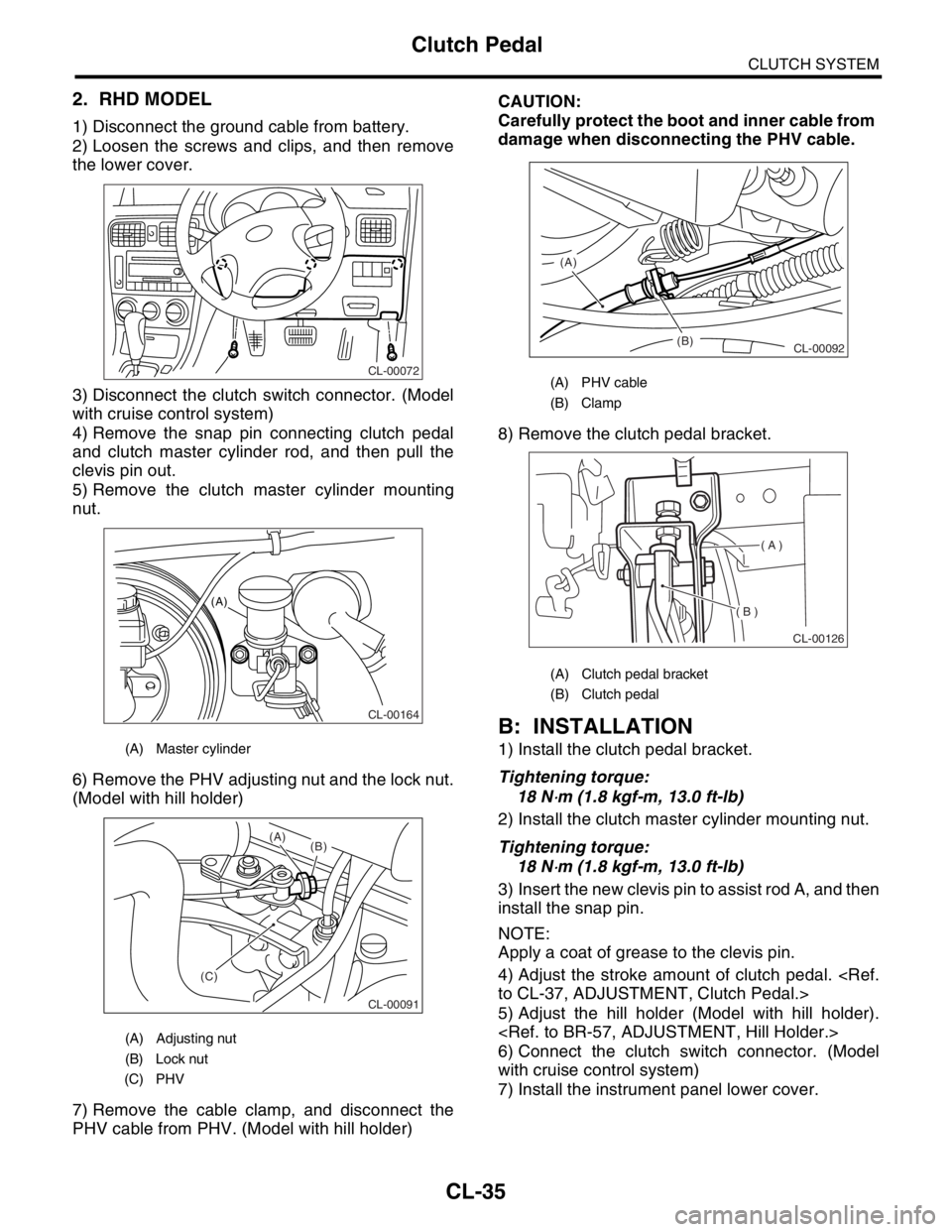
2. RHD MODEL
1) Disconnect the ground cable from battery.
2) Loosen the screws and clips, and then remove
the lower cover.
3) Disconnect the clutch switch connector. (Model
with cruise control system)
4) Remove the snap pin connecting clutch pedal
and clutch master cylinder rod, and then pull the
clevis pin out.
5) Remove the clutch master cylinder mounting
nut.
6) Remove the PHV adjusting nut and the lock nut.
(Model with hill holder)
7) Remove the cable clamp, and disconnect the
PHV cable from PHV. (Model with hill holder)CAUTION:
Carefully protect the boot and inner cable from
damage when disconnecting the PHV cable.
8) Remove the clutch pedal bracket.
B: INSTALLATION
1) Install the clutch pedal bracket.
Tightening torque:
18 N
⋅m (1.8 kgf-m, 13.0 ft-lb)
2) Install the clutch master cylinder mounting nut.
Tightening torque:
18 N
⋅m (1.8 kgf-m, 13.0 ft-lb)
3) Insert the new clevis pin to assist rod A, and then
install the snap pin.
NOTE:
Apply a coat of grease to the clevis pin.
4) Adjust the stroke amount of clutch pedal.
5) Adjust the hill holder (Model with hill holder).
6) Connect the clutch switch connector. (Model
with cruise control system)
7) Install the instrument panel lower cover.
(A) Master cylinder
(A) Adjusting nut
(B) Lock nut
(C) PHV
CL-00072
CL-00164
(A)
CL-00091
(C)(B) (A)
(A) PHV cable
(B) Clamp
(A) Clutch pedal bracket
(B) Clutch pedal
(B) (A)
CL-00092
( A )
( B )
CL-00126
Page 2867 of 2870
CL-41
CLUTCH SYSTEM
Clutch Switch
11.Clutch Switch
A: REMOVAL
1) Disconnect the ground cable from battery.
2) Remove the instrument panel lower cover.
3) Disconnect the connector from clutch switch.
4) Remove the clutch switch.
B: INSTALLATION
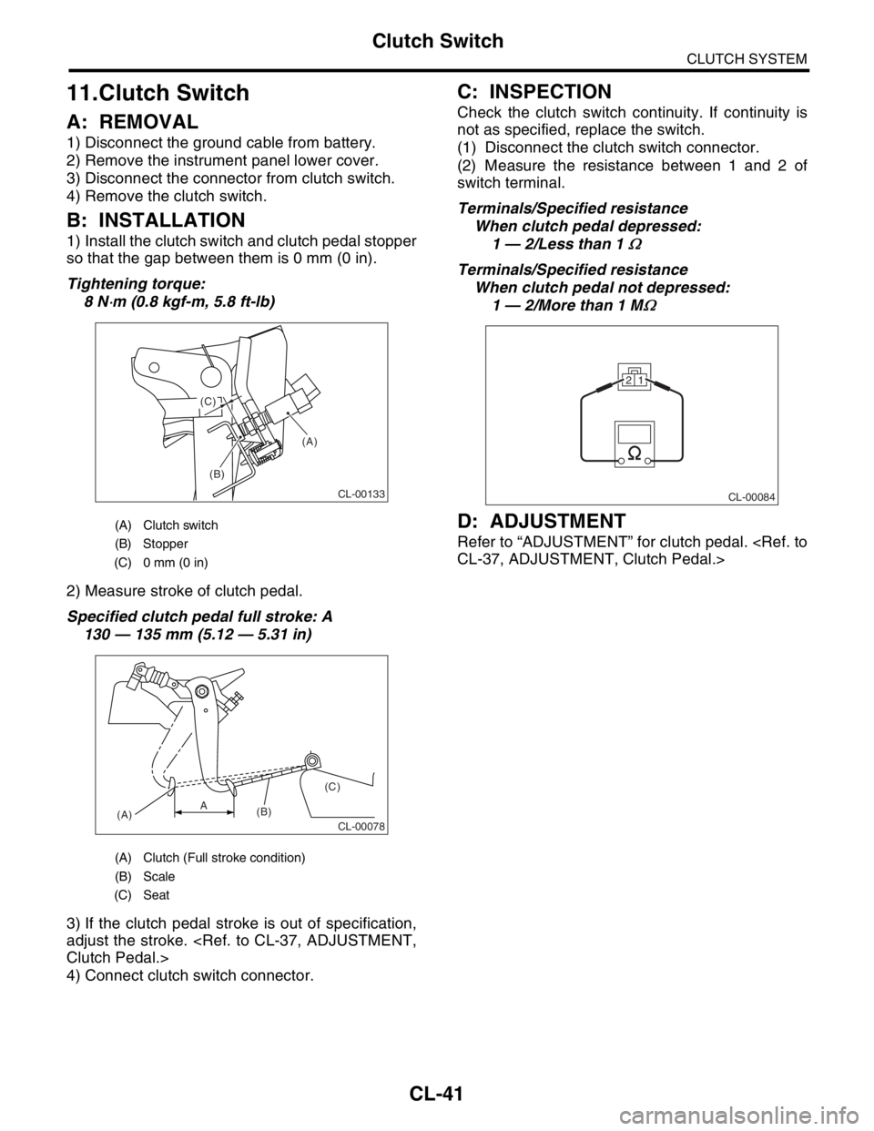
1) Install the clutch switch and clutch pedal stopper
so that the gap between them is 0 mm (0 in).
Tightening torque:
8 N
⋅m (0.8 kgf-m, 5.8 ft-lb)
2) Measure stroke of clutch pedal.
Specified clutch pedal full stroke: A
130 — 135 mm (5.12 — 5.31 in)
3) If the clutch pedal stroke is out of specification,
adjust the stroke.
4) Connect clutch switch connector.
C: INSPECTION
Check the clutch switch continuity. If continuity is
not as specified, replace the switch.
(1) Disconnect the clutch switch connector.
(2) Measure the resistance between 1 and 2 of
switch terminal.
Terminals/Specified resistance
When clutch pedal depressed:
1 — 2/Less than 1
Ω
Terminals/Specified resistance
When clutch pedal not depressed:
1 — 2/More than 1 M
Ω
D: ADJUSTMENT
Refer to “ADJUSTMENT” for clutch pedal.
(A) Clutch switch
(B) Stopper
(C) 0 mm (0 in)
(A) Clutch (Full stroke condition)
(B) Scale
(C) Seat
(A)
(B) (C)
CL-00133
CL-00078(A)(B)(C)A
CL-00084
21