2004 SUBARU FORESTER instrument panel
[x] Cancel search: instrument panelPage 577 of 2870
CC(H4SO)-9
CRUISE CONTROL SYSTEM (DIAGNOSTIC)
Subaru Select Monitor
5. Subaru Select Monitor
A: OPERATION
1. GENERAL
The on-board diagnosis function of the cruise control
system uses an external Subaru Select Monitor.
The on-board diagnosis function operates in two cat-
egories, which are used depending on the type of
problems;
1) Cruise cancel conditions diagnosis:
(1) This category of diagnosis requires actual
vehicle driving in order to determine the cause,
(as when cruise speed is cancelled during driv-
ing although cruise cancel condition is not en-
tered).
(2) Cruise control module memory stores the
cancel condition (Code No.) which occurred dur-
ing driving. When there are plural cancel condi-
tions (Code No.), they are shown on the Subaru
Select Monitor.
CAUTION:
The cruise control memory stores not only the
cruise “cancel” which occurred (although “can-
cel” operation is not entered by the driver), but
also the “cancel” condition input by the driver.
The content of memory is cleared when igni-
tion switch or cruise main switch is turned OFF.
2) Real-time diagnosis:
The real-time diagnosis function is used to deter-
mine whether or not the input signal system is in
good order, according to signal emitted from
switches, sensors, etc.
(1) Vehicle cannot be driven at cruise speed be-
cause problem occurs in the cruise control sys-
tem or its associated circuits.
(2) Monitor the signal conditions from switches
and sensors.
2. CRUISE CANCEL CONDITIONS DIAG-
NOSIS
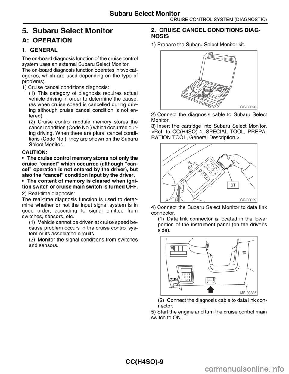
1) Prepare the Subaru Select Monitor kit.
2) Connect the diagnosis cable to Subaru Select
Monitor.
3) Insert the cartridge into Subaru Select Monitor.
4) Connect the Subaru Select Monitor to data link
connector.
(1) Data link connector is located in the lower
portion of the instrument panel (on the driver’s
side).
(2) Connect the diagnosis cable to data link con-
nector.
5) Start the engine and turn the cruise control main
switch to ON.
CC-00028
CC-00029
ME-00325
Page 607 of 2870
FUJI HEAVY INDUSTRIES LTD. G8080GE7
2004 FORESTER SERVICE MANUAL QUICK REFERENCE INDEX
BODY SECTION
This service manual has been prepared
to provide SUBARU service personnel
with the necessary information and data
for the correct maintenance and repair
of SUBARU vehicles.
This manual includes the procedures
for maintenance, disassembling, reas-
sembling, inspection and adjustment of
components and diagnostics for guid-
ance of experienced mechanics.
Please peruse and utilize this manual
fully to ensure complete repair work for
satisfying our customers by keeping
their vehicle in optimum condition.
When replacement of parts during
repair work is needed, be sure to use
SUBARU genuine parts.
All information, illustration and specifi-
cations contained in this manual are
based on the latest product information
available at the time of publication
approval.HVAC SYSTEM
(HEATER, VENTILATOR AND A/C)AC
HVAC SYSTEM (AUTO A/C)
(DIAGNOSTIC)AC
AIRBAG SYSTEM AB
AIRBAG SYSTEM (DIAGNOSTIC) AB
SEAT BELT SYSTEM SB
LIGHTING SYSTEM LI
WIPER AND WASHER SYSTEM WW
ENTERTAINMENT ET
COMMUNICATION SYSTEM COM
GLASS/WINDOW/MIRROR GW
BODY STRUCTURE BS
INSTRUMENTATION/DRIVER INFO IDI
SEAT SE
SECURITY AND LOCK SL
SUNROOF/T-TOP/CONVERTIBLE TOP
(SUNROOF)SR
EXTERIOR/INTERIOR TRIM EI
EXTERIOR BODY PANEL EB
Page 611 of 2870
FUJI HEAVY INDUSTRIES LTD. G8080GE7
2004 FORESTER SERVICE MANUAL QUICK REFERENCE INDEX
BODY SECTION
This service manual has been prepared
to provide SUBARU service personnel
with the necessary information and data
for the correct maintenance and repair
of SUBARU vehicles.
This manual includes the procedures
for maintenance, disassembling, reas-
sembling, inspection and adjustment of
components and diagnostics for guid-
ance of experienced mechanics.
Please peruse and utilize this manual
fully to ensure complete repair work for
satisfying our customers by keeping
their vehicle in optimum condition.
When replacement of parts during
repair work is needed, be sure to use
SUBARU genuine parts.
All information, illustration and specifi-
cations contained in this manual are
based on the latest product information
available at the time of publication
approval.HVAC SYSTEM
(HEATER, VENTILATOR AND A/C)AC
HVAC SYSTEM (AUTO A/C)
(DIAGNOSTIC)AC
AIRBAG SYSTEM AB
AIRBAG SYSTEM (DIAGNOSTIC) AB
SEAT BELT SYSTEM SB
LIGHTING SYSTEM LI
WIPER AND WASHER SYSTEM WW
ENTERTAINMENT ET
COMMUNICATION SYSTEM COM
GLASS/WINDOW/MIRROR GW
BODY STRUCTURE BS
INSTRUMENTATION/DRIVER INFO IDI
SEAT SE
SECURITY AND LOCK SL
SUNROOF/T-TOP/CONVERTIBLE TOP
(SUNROOF)SR
EXTERIOR/INTERIOR TRIM EI
EXTERIOR BODY PANEL EB
Page 620 of 2870
CC(H4DOTC 2.5)-8
CRUISE CONTROL SYSTEM (DIAGNOSTIC)
Subaru Select Monitor
5. Subaru Select Monitor
A: OPERATION
1. GENERAL
The on-board diagnosis function of the cruise con-
trol system uses the Subaru Select Monitor.
The on-board diagnosis function operates in two
categories, which are used depending on the type
of problems;
1) Cruise cancel conditions diagnosis:
(1) This category of diagnosis requires actual ve-
hicle driving in order to determine the cause, (as
when cruise speed is cancelled during driving al-
though cruise cancel condition is not entered).
(2) Cruise control memory of ECM stores the
cancel condition (Code No.) which occurred dur-
ing driving. When there are plural cancel condi-
tions (Code No.), they are shown on the Subaru
Select Monitor.
CAUTION:
The cruise control memory stores not only the
cruise “cancel” which occurred (although “can-
cel” operation is not entered by the driver), but
also the “cancel” condition input by the driver.
The content of memory is cleared when igni-
tion switch or cruise main switch is turned OFF.
2) Real-time diagnosis:
The real-time diagnosis function is used to deter-
mine whether or not the input signal system is in
good order, according to signal emitted from
switches, sensors, etc.
(1) Vehicle cannot be driven at cruise speed be-
cause problem occurs in the cruise control sys-
tem or its associated circuits.
(2) Monitor the signal conditions from switches
and sensors.
2. CRUISE CANCEL CONDITIONS DIAG-
NOSIS
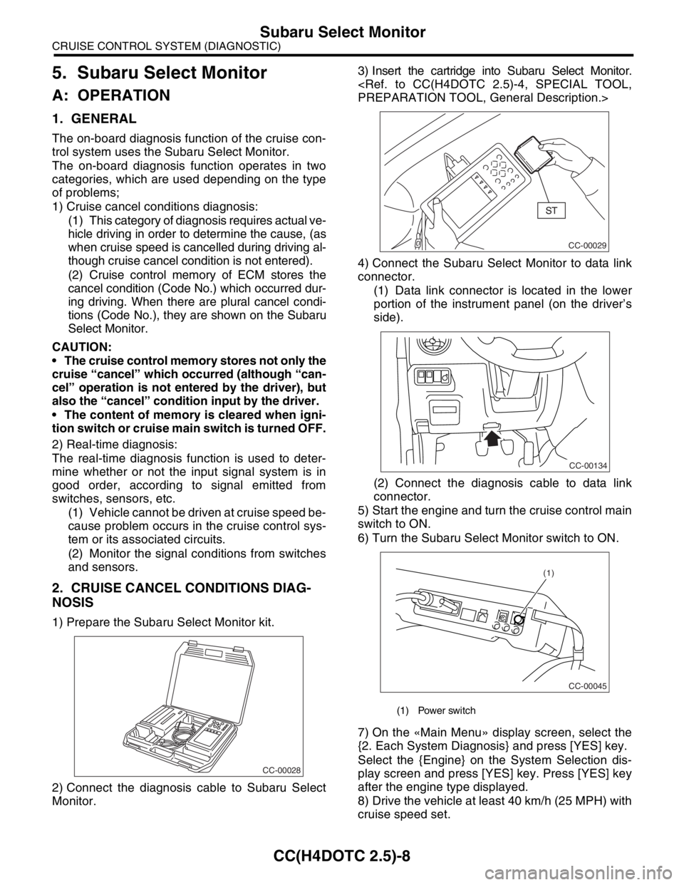
1) Prepare the Subaru Select Monitor kit.
2) Connect the diagnosis cable to Subaru Select
Monitor.3) Insert the cartridge into Subaru Select Monitor.
4) Connect the Subaru Select Monitor to data link
connector.
(1) Data link connector is located in the lower
portion of the instrument panel (on the driver’s
side).
(2) Connect the diagnosis cable to data link
connector.
5) Start the engine and turn the cruise control main
switch to ON.
6) Turn the Subaru Select Monitor switch to ON.
7) On the «Main Menu» display screen, select the
{2. Each System Diagnosis} and press [YES] key.
Select the {Engine} on the System Selection dis-
play screen and press [YES] key. Press [YES] key
after the engine type displayed.
8) Drive the vehicle at least 40 km/h (25 MPH) with
cruise speed set.
CC-00028
(1) Power switch
CC-00029
CC-00134
CC-00045
(1)
Page 641 of 2870
FUJI HEAVY INDUSTRIES LTD. G8080GE7
2004 FORESTER SERVICE MANUAL QUICK REFERENCE INDEX
BODY SECTION
This service manual has been prepared
to provide SUBARU service personnel
with the necessary information and data
for the correct maintenance and repair
of SUBARU vehicles.
This manual includes the procedures
for maintenance, disassembling, reas-
sembling, inspection and adjustment of
components and diagnostics for guid-
ance of experienced mechanics.
Please peruse and utilize this manual
fully to ensure complete repair work for
satisfying our customers by keeping
their vehicle in optimum condition.
When replacement of parts during
repair work is needed, be sure to use
SUBARU genuine parts.
All information, illustration and specifi-
cations contained in this manual are
based on the latest product information
available at the time of publication
approval.HVAC SYSTEM
(HEATER, VENTILATOR AND A/C)AC
HVAC SYSTEM (AUTO A/C)
(DIAGNOSTIC)AC
AIRBAG SYSTEM AB
AIRBAG SYSTEM (DIAGNOSTIC) AB
SEAT BELT SYSTEM SB
LIGHTING SYSTEM LI
WIPER AND WASHER SYSTEM WW
ENTERTAINMENT ET
COMMUNICATION SYSTEM COM
GLASS/WINDOW/MIRROR GW
BODY STRUCTURE BS
INSTRUMENTATION/DRIVER INFO IDI
SEAT SE
SECURITY AND LOCK SL
SUNROOF/T-TOP/CONVERTIBLE TOP
(SUNROOF)SR
EXTERIOR/INTERIOR TRIM EI
EXTERIOR BODY PANEL EB
Page 649 of 2870
IM-7
IMMOBILIZER (DIAGNOSTIC)
Subaru Select Monitor
5. Subaru Select Monitor
A: OPERATION
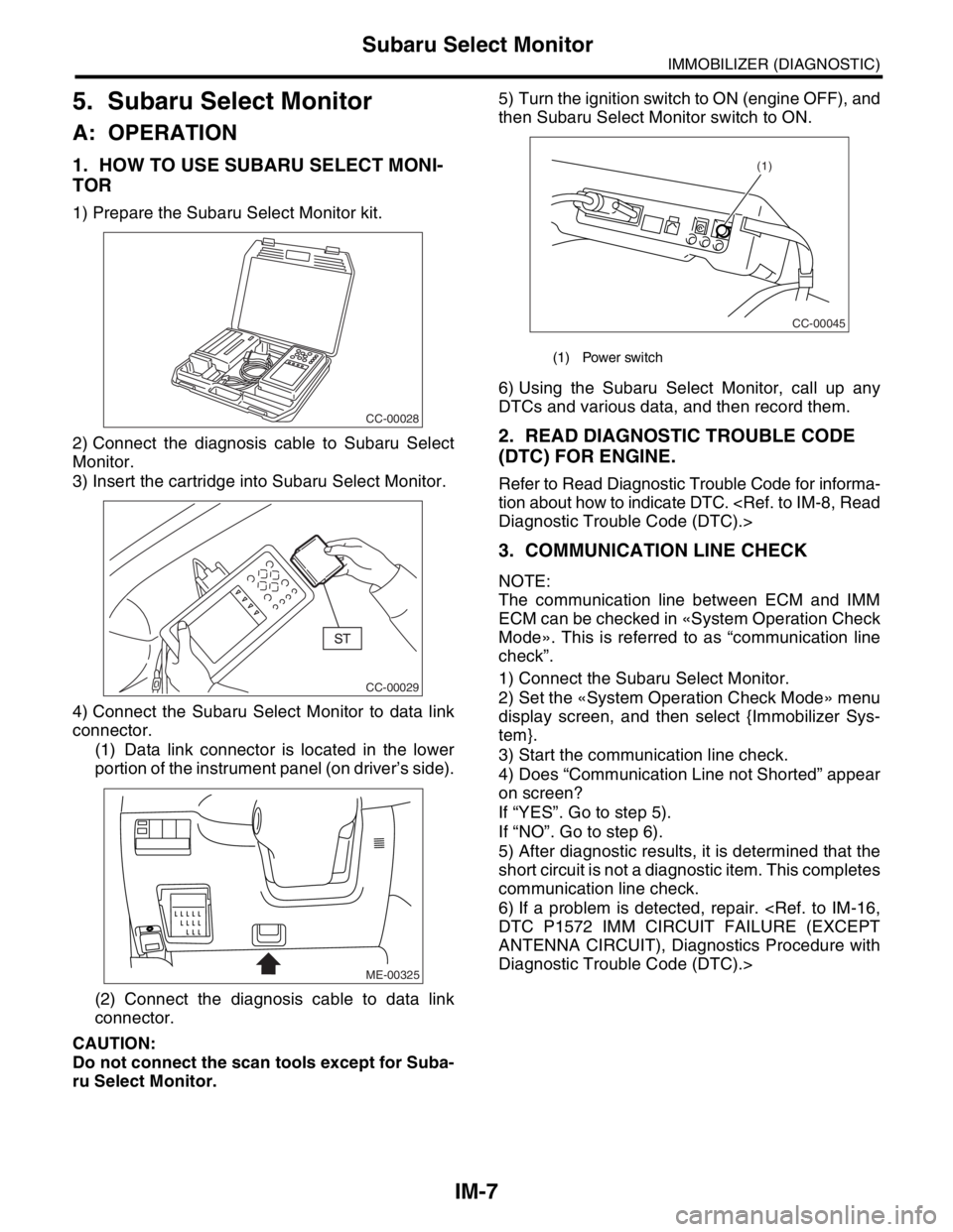
1. HOW TO USE SUBARU SELECT MONI-
TOR
1) Prepare the Subaru Select Monitor kit.
2) Connect the diagnosis cable to Subaru Select
Monitor.
3) Insert the cartridge into Subaru Select Monitor.
4) Connect the Subaru Select Monitor to data link
connector.
(1) Data link connector is located in the lower
portion of the instrument panel (on driver’s side).
(2) Connect the diagnosis cable to data link
connector.
CAUTION:
Do not connect the scan tools except for Suba-
ru Select Monitor.5) Turn the ignition switch to ON (engine OFF), and
then Subaru Select Monitor switch to ON.
6) Using the Subaru Select Monitor, call up any
DTCs and various data, and then record them.
2. READ DIAGNOSTIC TROUBLE CODE
(DTC) FOR ENGINE.
Refer to Read Diagnostic Trouble Code for informa-
tion about how to indicate DTC.
3. COMMUNICATION LINE CHECK
NOTE:
The communication line between ECM and IMM
ECM can be checked in «System Operation Check
Mode». This is referred to as “communication line
check”.
1) Connect the Subaru Select Monitor.
2) Set the «System Operation Check Mode» menu
display screen, and then select {Immobilizer Sys-
tem}.
3) Start the communication line check.
4) Does “Communication Line not Shorted” appear
on screen?
If “YES”. Go to step 5).
If “NO”. Go to step 6).
5) After diagnostic results, it is determined that the
short circuit is not a diagnostic item. This completes
communication line check.
6) If a problem is detected, repair.
ANTENNA CIRCUIT), Diagnostics Procedure with
Diagnostic Trouble Code (DTC).>
CC-00028
CC-00029
ME-00325
(1) Power switch
CC-00045
(1)
Page 1057 of 2870
SP(H4SO)-4
SPEED CONTROL SYSTEM
Accelerator Pedal
2. Accelerator Pedal
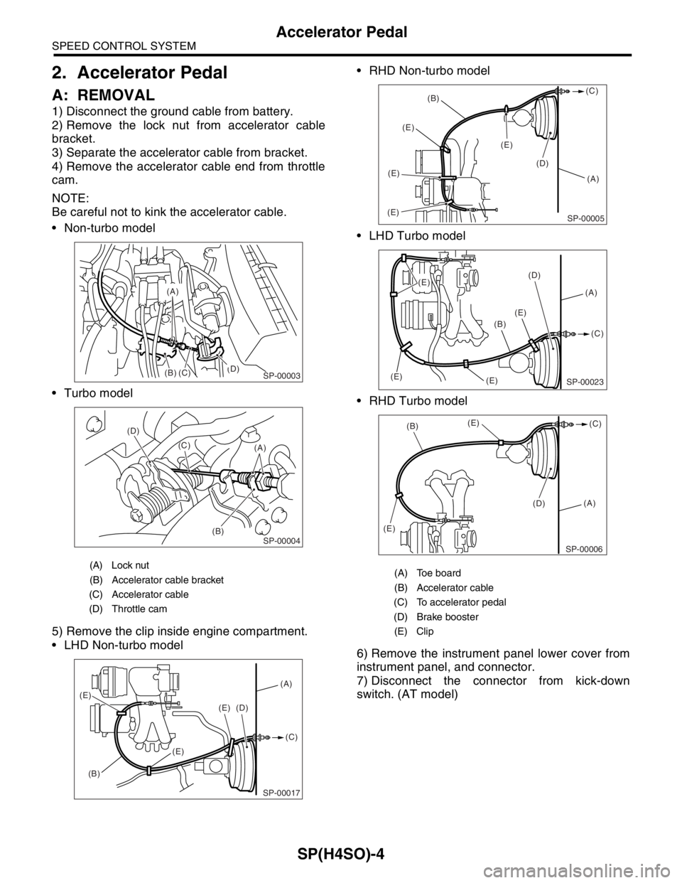
A: REMOVAL
1) Disconnect the ground cable from battery.
2) Remove the lock nut from accelerator cable
bracket.
3) Separate the accelerator cable from bracket.
4) Remove the accelerator cable end from throttle
cam.
NOTE:
Be careful not to kink the accelerator cable.
Non-turbo model
Turbo model
5) Remove the clip inside engine compartment.
LHD Non-turbo model RHD Non-turbo model
LHD Turbo model
RHD Turbo model
6) Remove the instrument panel lower cover from
instrument panel, and connector.
7) Disconnect the connector from kick-down
switch. (AT model)
(A) Lock nut
(B) Accelerator cable bracket
(C) Accelerator cable
(D) Throttle cam
(B)(D)
(C)
(A)
SP-00003
(B) (D)
(C)
(A)SP-00004
SP-00017
(A)
(B)(C) (D)
(E)
(E)
(E)
(A) Toe board
(B) Accelerator cable
(C) To accelerator pedal
(D) Brake booster
(E) Clip
(A) (B)(C)
(E)(E)(E)
(E)
(D)
SP-00005
(A) (D)
(E)
(E) (E)(C)
(B)
(E)
SP-00023
(A)
(D) (E)
(E)(B)(C)
SP-00006
Page 1125 of 2870
EN(H4SO)-27
ENGINE (DIAGNOSTIC)
OBD-II General Scan Tool
9. OBD-II General Scan Tool
A: OPERATION
1. HOW TO USE OBD-II GENERAL SCAN
TOOL
1) Prepare a general scan tool (OBD-II general
scan tool) required by SAE J1978.
2) Connect the OBD-II general scan tool to its data
link connector in the lower portion of the instrument
panel (on the driver’s side).3) Using the OBD-II general scan tool, call up the
DTC and freeze frame data.
OBD-II general scan tool functions consist of:
(1) MODE $01: Current powertrain diagnostic
data
(2) MODE $02: Powertrain freeze frame data
(3) MODE $03: Emission-related powertrain
DTC
(4) MODE $04: Clear/Reset emission-related
diagnostic information
Read out data according to repair procedures. (For
detailed operation procedures, refer to the OBD-II
General Scan Tool Operation Manual.)
NOTE:
For details concerning DTCs, refer to the List of Di-
agnostic Trouble Code (DTC).
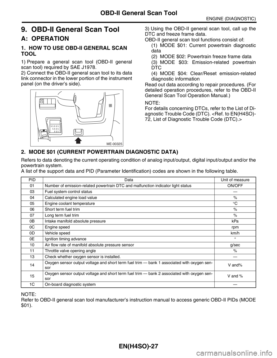
2. MODE $01 (CURRENT POWERTRAIN DIAGNOSTIC DATA)
Refers to data denoting the current operating condition of analog input/output, digital input/output and/or the
powertrain system.
A list of the support data and PID (Parameter Identification) codes are shown in the following table.
NOTE:
Refer to OBD-II general scan tool manufacturer’s instruction manual to access generic OBD-II PIDs (MODE
$01).
ME-00325
PID Data Unit of measure
01 Number of emission-related powertrain DTC and malfunction indicator light status ON/OFF
03 Fuel system control status—
04 Calculated engine load value%
05 Engine coolant temperature°C
06 Short term fuel trim%
07 Long term fuel trim%
0B Intake manifold absolute pressure kPa
0C Engine speedrpm
0D Vehicle speedkm/h
0E Ignition timing advance°
10 Air flow rate of manifold absolute pressure sensor g/sec
11 Throttle valve opening angle%
13 Check whether oxygen sensor is installed. —
14Oxygen sensor output voltage and short term fuel trim — bank 1 associated with oxygen sen-
sorV and%
15Oxygen sensor output voltage and short term fuel trim — bank 2 associated with oxygen sen-
sorV and %
1C On-board diagnostic system—