Page 1 of 2870

FUJI HEAVY INDUSTRIES LTD. G8080GE7
2004 FORESTER SERVICE MANUAL QUICK REFERENCE INDEX
BODY SECTION
This service manual has been prepared
to provide SUBARU service personnel
with the necessary information and data
for the correct maintenance and repair
of SUBARU vehicles.
This manual includes the procedures
for maintenance, disassembling, reas-
sembling, inspection and adjustment of
components and diagnostics for guid-
ance of experienced mechanics.
Please peruse and utilize this manual
fully to ensure complete repair work for
satisfying our customers by keeping
their vehicle in optimum condition.
When replacement of parts during
repair work is needed, be sure to use
SUBARU genuine parts.
All information, illustration and specifi-
cations contained in this manual are
based on the latest product information
available at the time of publication
approval.HVAC SYSTEM
(HEATER, VENTILATOR AND A/C)AC
HVAC SYSTEM (AUTO A/C)
(DIAGNOSTIC)AC
AIRBAG SYSTEM AB
AIRBAG SYSTEM (DIAGNOSTIC) AB
SEAT BELT SYSTEM SB
LIGHTING SYSTEM LI
WIPER AND WASHER SYSTEM WW
ENTERTAINMENT ET
COMMUNICATION SYSTEM COM
GLASS/WINDOW/MIRROR GW
BODY STRUCTURE BS
INSTRUMENTATION/DRIVER INFO IDI
SEAT SE
SECURITY AND LOCK SL
SUNROOF/T-TOP/CONVERTIBLE TOP
(SUNROOF)SR
EXTERIOR/INTERIOR TRIM EI
EXTERIOR BODY PANEL EB
Page 37 of 2870

AC-35
HVAC SYSTEM (HEATER, VENTILATOR AND A/C)
Control Unit
10.Control Unit
A: REMOVAL
1) Disconnect the ground cable from battery.
2) In case of manual A/C, remove the mode cable
and air-mix cable from links of heater unit.
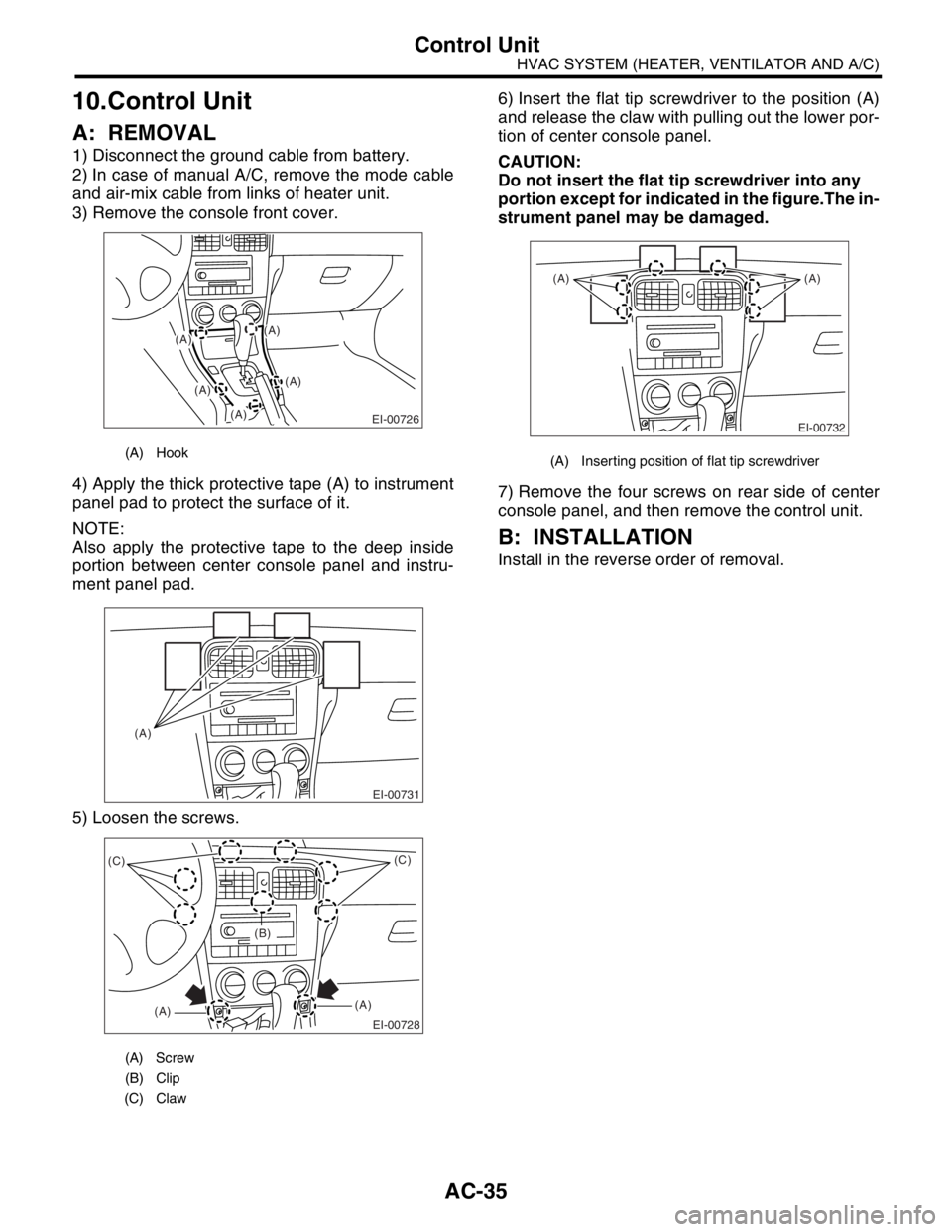
3) Remove the console front cover.
4) Apply the thick protective tape (A) to instrument
panel pad to protect the surface of it.
NOTE:
Also apply the protective tape to the deep inside
portion between center console panel and instru-
ment panel pad.
5) Loosen the screws.6) Insert the flat tip screwdriver to the position (A)
and release the claw with pulling out the lower por-
tion of center console panel.
CAUTION:
Do not insert the flat tip screwdriver into any
portion except for indicated in the figure.The in-
strument panel may be damaged.
7) Remove the four screws on rear side of center
console panel, and then remove the control unit.
B: INSTALLATION
Install in the reverse order of removal.
(A) Hook
(A) Screw
(B) Clip
(C) Claw
(A)
(A)
EI-00726
(A)
(A)
(A)
EI-00731
(A)
EI-00728
(C)
(A)(A)(C)
(B)
(A) Inserting position of flat tip screwdriver
EI-00732
(A) (A)
Page 41 of 2870
AC-39
HVAC SYSTEM (HEATER, VENTILATOR AND A/C)
Heater Cooling Unit
14.Heater Cooling Unit
A: REMOVAL
1) Disconnect the ground cable from battery.
2) Using the refrigerant recovery system, dis-
charge refrigerant.
Refrigerant Recovery Procedure.>
3) Drain the engine coolant from radiator.
4) Remove the bolt securing expansion valve and
pipe in engine compartment. Release the heater
hose clamps in engine compartment to remove the
hoses.
5) Remove the instrument panel.
REMOVAL, Instrument Panel Assembly.>
6) Remove the support beam.
7) Remove the blower motor unit assembly.
to AC-32, REMOVAL, Blower Motor Unit Assem-
bly.>
8) Disconnect the servo motor connectors.
9) Remove the bolt and nuts to remove the heater
and cooling unit.
B: INSTALLATION
1) Install in the reverse order of removal.
2) Charge refrigerant.
TION, Refrigerant Charging Procedure.>
Tightening torque:
Refer to COMPONENT in General Descrip-
tion.
COMPONENT, General Description.>
AC-00870
AC-00055
Page 48 of 2870
AC-46
HVAC SYSTEM (HEATER, VENTILATOR AND A/C)
Air Vent Grille
21.Air Vent Grille
A: REMOVAL
1. CENTER GRILLE
1) Disconnect the ground cable from battery.
2) Remove the center console panel.
40, REMOVAL, Instrument Panel Assembly.>
3) Loosen the two screws to remove the center air
vent grille.
2. SIDE GRILLE
Remove the side vent grille by prying four points.
B: INSTALLATION
Install in the reverse order of removal.
C: INSPECTION
1) Check that the direction and amount of air can
be adjusted smoothly.
2) Check that the adjustment can be kept in each
position.
AC-00060
AC-00249
Page 50 of 2870
AC-48
HVAC SYSTEM (HEATER, VENTILATOR AND A/C)
Heater Vent Duct
23.Heater Vent Duct
A: REMOVAL
1) Remove the instrument panel.
2) Remove the screws.
3) Remove the heater vent duct.
B: INSTALLATION
Install in the reverse order of removal.
AC-00224
Page 55 of 2870

FUJI HEAVY INDUSTRIES LTD. G8080GE7
2004 FORESTER SERVICE MANUAL QUICK REFERENCE INDEX
BODY SECTION
This service manual has been prepared
to provide SUBARU service personnel
with the necessary information and data
for the correct maintenance and repair
of SUBARU vehicles.
This manual includes the procedures
for maintenance, disassembling, reas-
sembling, inspection and adjustment of
components and diagnostics for guid-
ance of experienced mechanics.
Please peruse and utilize this manual
fully to ensure complete repair work for
satisfying our customers by keeping
their vehicle in optimum condition.
When replacement of parts during
repair work is needed, be sure to use
SUBARU genuine parts.
All information, illustration and specifi-
cations contained in this manual are
based on the latest product information
available at the time of publication
approval.HVAC SYSTEM
(HEATER, VENTILATOR AND A/C)AC
HVAC SYSTEM (AUTO A/C)
(DIAGNOSTIC)AC
AIRBAG SYSTEM AB
AIRBAG SYSTEM (DIAGNOSTIC) AB
SEAT BELT SYSTEM SB
LIGHTING SYSTEM LI
WIPER AND WASHER SYSTEM WW
ENTERTAINMENT ET
COMMUNICATION SYSTEM COM
GLASS/WINDOW/MIRROR GW
BODY STRUCTURE BS
INSTRUMENTATION/DRIVER INFO IDI
SEAT SE
SECURITY AND LOCK SL
SUNROOF/T-TOP/CONVERTIBLE TOP
(SUNROOF)SR
EXTERIOR/INTERIOR TRIM EI
EXTERIOR BODY PANEL EB
Page 59 of 2870

AC-3
HVAC SYSTEM (AUTO A/C)(DIAGNOSTIC)
General Description
2. General Description
A: CAUTION
1) Never connect the battery in reverse polarity.
Auto A/C control module may be destroyed instant-
ly.
2) Do not disconnect the battery terminals while the
engine is running.
A large counter electromotive force will be generat-
ed in the generator, and this voltage may damage
electronic parts such as auto A/C control module,
etc.
3) Before disconnecting the connectors of each
sensor and the auto A/C control module, be sure to
turn off the ignition switch.
Auto A/C control module may be damaged.
4) Every A/C-related part is a precision part. Do not
drop them.
5) Airbag system wiring harness is routed near the
A/C control panel (auto A/C control module) and
junction box.
CAUTION:
For airbag system, yellow-colored wiring har-
ness and connectors are all used. Do not use
the electrical test equipment on these circuits.
Be careful not to damage the airbag system
wiring harness when servicing the A/C control
panel (auto A/C control module) and junction
box.
B: INSPECTION
Before performing the diagnosis, check the follow-
ing items which might affect A/C system problems.
1. BATTERY
1) Measure battery voltage and specific gravity of
electrolyte.
Standard voltage: 12 V
Specific gravity: More than 1.260
2) Check the condition of the fuses for A/C system
power supply and other fuses.
3) Check the condition of harness and harness
connector connections.
2. ASPIRATOR HOSE
1) Turn the ignition switch to ON, and press the A/
C switch.
2) Turn the temperature control dial at maximum
hot position.
3) Press the defroster switch.
4) Turn the fan speed control dial to 4th position.5) Approach a strip of paper (b) in front of the in-ve-
hicle sensor suction port (a) located in the instru-
ment lower cover, and check that air is being
sucked into the port by seeing the paper moving to-
wards port.
NOTE:
Be careful not to let the paper get sucked into port.
6) If the paper does not move at all, remove the in-
strument panel lower cover
MOVAL, Instrument Panel Assembly.> and check
for improper connection of the aspirator hose (a),
in-vehicle sensor and heater unit, and repair them if
necessary.
3. A/C LINE
Check the connection for A/C line (A) and lower
side high-pressure pipe.
4. CONTROL LINKAGE
1) Check the state of mode door linkage.
2) Check the state of air mix door linkage.
3) Check the state of intake door linkage.
AC-00094
(a)
(a)
(b)
AC-00065
(a)
AC-00096
(A)
Page 92 of 2870

AC-36
HVAC SYSTEM (AUTO A/C)(DIAGNOSTIC)
Diagnostic Procedure for Sensors
Step Check Yes No
1 CHECK IN-VEHICLE SENSOR.
1) Turn the ignition switch to OFF.
2) Remove the instrument panel lower cover.
3) Disconnect the connector from in-vehicle
sensor.
4) Measure the resistance between connector
terminals of in-vehicle sensor.
Te r m i n a l s
No. 1 — No. 2:Is the resistance approx. 2.7
kΩ at 20°C (68°F)?Go to step 2.Replace the in-
vehicle sensor.
2 CHECK INPUT SIGNAL FOR IN-VEHICLE
SENSOR.
1) Turn the ignition switch to ON.
2) Measure the voltage between in-vehicle
sensor harness connector terminal and chas-
sis ground.
Connector & terminal
LHD model:
(i55) No. 2 (+) — Chassis ground (
−):
RHD model:
(B314) No. 2 (+) — Chassis ground (
−):Is the voltage approx. 5 V? Go to step 6.Go to step 3.
3 CHECK AUTO A/C CONTROL MODULE
OUTPUT SIGNAL.
1) Turn the ignition switch to OFF.
2) Remove the auto A/C control module.
3) Turn the ignition switch to ON.
4) Measure the voltage between connector
terminals of auto A/C control module.
Connector & terminal
(i49) No. 12 (+) — (i48) No. 16:Is the voltage approx. 5 V? Go to step 4.Go to step 6.
4 CHECK HARNESS BETWEEN AUTO A/C
CONTROL MODULE AND IN-VEHICLE SEN-
SOR.
1) Turn the ignition switch to OFF.
2) Disconnect the connector from auto A/C
control module.
3) Measure the resistance in harness
between auto A/C control module and in-vehi-
cle sensor.
Connector & terminal
LHD model:
(i55) No. 2 — (i49) No. 12:
RHD model:
(B314) No. 2 — (i49) No. 12:Is the resistance less than 1
Ω?Go to step 5.Repair the har-
ness between auto
A/C control mod-
ule and in-vehicle
sensor.
5 CHECK HARNESS BETWEEN AUTO A/C
CONTROL MODULE AND IN-VEHICLE SEN-
SOR.
Measure the resistance in harness between
auto A/C control module and in-vehicle sensor.
Connector & terminal
LHD model:
(i55) No. 1 — (i48) No. 16:
RHD model:
(B314) No. 1 — (i48) No. 16:Is the resistance less than 1
Ω?Go to step 6.Repair the har-
ness between auto
A/C control mod-
ule and in-vehicle
sensor.
6 CHECK POOR CONTACT.
Check poor contact in auto A/C control module
connector.Is there poor contact in con-
nector?Repair the con-
nector.Replace the auto
A/C control mod-
ule.