2004 SUBARU FORESTER instrument panel
[x] Cancel search: instrument panelPage 99 of 2870
FUJI HEAVY INDUSTRIES LTD. G8080GE7
2004 FORESTER SERVICE MANUAL QUICK REFERENCE INDEX
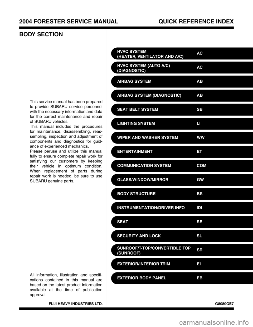
BODY SECTION
This service manual has been prepared
to provide SUBARU service personnel
with the necessary information and data
for the correct maintenance and repair
of SUBARU vehicles.
This manual includes the procedures
for maintenance, disassembling, reas-
sembling, inspection and adjustment of
components and diagnostics for guid-
ance of experienced mechanics.
Please peruse and utilize this manual
fully to ensure complete repair work for
satisfying our customers by keeping
their vehicle in optimum condition.
When replacement of parts during
repair work is needed, be sure to use
SUBARU genuine parts.
All information, illustration and specifi-
cations contained in this manual are
based on the latest product information
available at the time of publication
approval.HVAC SYSTEM
(HEATER, VENTILATOR AND A/C)AC
HVAC SYSTEM (AUTO A/C)
(DIAGNOSTIC)AC
AIRBAG SYSTEM AB
AIRBAG SYSTEM (DIAGNOSTIC) AB
SEAT BELT SYSTEM SB
LIGHTING SYSTEM LI
WIPER AND WASHER SYSTEM WW
ENTERTAINMENT ET
COMMUNICATION SYSTEM COM
GLASS/WINDOW/MIRROR GW
BODY STRUCTURE BS
INSTRUMENTATION/DRIVER INFO IDI
SEAT SE
SECURITY AND LOCK SL
SUNROOF/T-TOP/CONVERTIBLE TOP
(SUNROOF)SR
EXTERIOR/INTERIOR TRIM EI
EXTERIOR BODY PANEL EB
Page 118 of 2870
AB-18
AIRBAG SYSTEM
Airbag Control Module
7. Airbag Control Module
A: REMOVAL
CAUTION:
Do not disassemble the airbag control mod-
ule.
If the airbag control module is deformed or if
water damage is suspected, replace the airbag
control module with a new part.
Do not drop the airbag control module.
After removal, keep the airbag control mod-
ule on a dry, clean surface away from moisture,
heat, and dust.
1) Turn the ignition switch to OFF.
2) Disconnect the ground cable from battery, and
wait for at least 20 seconds before starting work.
3) Remove the console cover.
4) Remove the center console panel.
5) Disconnect the connector from airbag control
module.
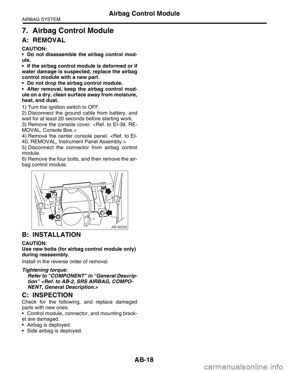
6) Remove the four bolts, and then remove the air-
bag control module.
B: INSTALLATION
CAUTION:
Use new bolts (for airbag control module only)
during reassembly.
Install in the reverse order of removal.
Tightening torque:
Refer to “COMPONENT” in “General Descrip-
tion”
C: INSPECTION
Check for the following, and replace damaged
parts with new ones.
Control module, connector, and mounting brack-
et are damaged.
Airbag is deployed.
Side airbag is deployed.
AB-00035
Page 122 of 2870
AB-22
AIRBAG SYSTEM
Airbag Module Disposal (Deployment Processing On Vehicle)
11.Airbag Module Disposal (De-
ployment Processing On Ve-
hicle)
A: OPERATION
CAUTION:
Do not discard an undeployed airbag mod-
ules because it may cause a serious personal
injury when accidentally deployed.
As a rule, the airbag module should be de-
ployed while still installed in the vehicle. Do not
remove the airbag modules unless necessary.
Deployment of the airbag module should be
done on a flat place free from any possible dan-
ger. Avoid deploying outdoors during rainy or
windy weather.
Deploying the airbag module causes a high
explosive noise, be sure to warn people in the
area, and do not allow anyone within a 5 m (16
ft) radius of the disposal site.
Some smoke will be emitted from deployment
of the airbag module. Therefore, it must be de-
ployed in a well-ventilated place with no smoke
detector nearby.
Wear protective gloves, safety goggles and
earplugs during this operation. Wash your hands
afterwards.
After deployment, the airbag module will be
especially hot, leave it unattended for 40 min-
utes, and then discard it.
Do not let water get on the deployed airbag
module.
Wrap the deployed airbag module in an air-
tight vinyl bag, and discard it.
If circumstances do not permit the airbag
module deployment, contact the SUBARU deal-
er.
1. DRIVER’S AIRBAG MODULE
1) Turn the ignition switch to OFF.
2) Disconnect the ground cable from battery and
wait for at least 20 seconds before starting work.
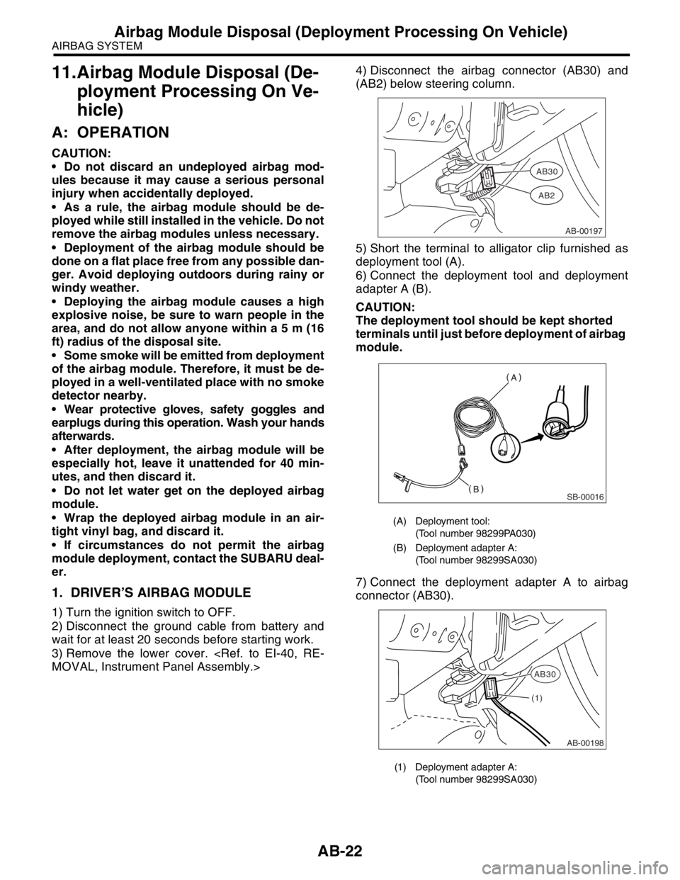
3) Remove the lower cover.
(AB2) below steering column.
5) Short the terminal to alligator clip furnished as
deployment tool (A).
6) Connect the deployment tool and deployment
adapter A (B).
CAUTION:
The deployment tool should be kept shorted
terminals until just before deployment of airbag
module.
7) Connect the deployment adapter A to airbag
connector (AB30).
(A) Deployment tool:
(Tool number 98299PA030)
(B) Deployment adapter A:
(Tool number 98299SA030)
(1) Deployment adapter A:
(Tool number 98299SA030)
AB-00197
AB30
AB2
SB-00016
AB-00198
AB30
(1)
Page 131 of 2870
FUJI HEAVY INDUSTRIES LTD. G8080GE7
2004 FORESTER SERVICE MANUAL QUICK REFERENCE INDEX
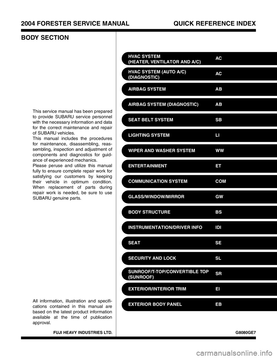
BODY SECTION
This service manual has been prepared
to provide SUBARU service personnel
with the necessary information and data
for the correct maintenance and repair
of SUBARU vehicles.
This manual includes the procedures
for maintenance, disassembling, reas-
sembling, inspection and adjustment of
components and diagnostics for guid-
ance of experienced mechanics.
Please peruse and utilize this manual
fully to ensure complete repair work for
satisfying our customers by keeping
their vehicle in optimum condition.
When replacement of parts during
repair work is needed, be sure to use
SUBARU genuine parts.
All information, illustration and specifi-
cations contained in this manual are
based on the latest product information
available at the time of publication
approval.HVAC SYSTEM
(HEATER, VENTILATOR AND A/C)AC
HVAC SYSTEM (AUTO A/C)
(DIAGNOSTIC)AC
AIRBAG SYSTEM AB
AIRBAG SYSTEM (DIAGNOSTIC) AB
SEAT BELT SYSTEM SB
LIGHTING SYSTEM LI
WIPER AND WASHER SYSTEM WW
ENTERTAINMENT ET
COMMUNICATION SYSTEM COM
GLASS/WINDOW/MIRROR GW
BODY STRUCTURE BS
INSTRUMENTATION/DRIVER INFO IDI
SEAT SE
SECURITY AND LOCK SL
SUNROOF/T-TOP/CONVERTIBLE TOP
(SUNROOF)SR
EXTERIOR/INTERIOR TRIM EI
EXTERIOR BODY PANEL EB
Page 163 of 2870
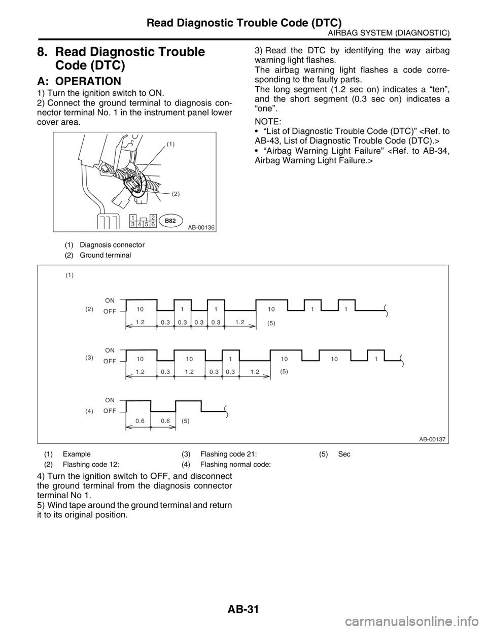
AB-31
AIRBAG SYSTEM (DIAGNOSTIC)
Read Diagnostic Trouble Code (DTC)
8. Read Diagnostic Trouble
Code (DTC)
A: OPERATION
1) Turn the ignition switch to ON.
2) Connect the ground terminal to diagnosis con-
nector terminal No. 1 in the instrument panel lower
cover area.3) Read the DTC by identifying the way airbag
warning light flashes.
The airbag warning light flashes a code corre-
sponding to the faulty parts.
The long segment (1.2 sec on) indicates a “ten”,
and the short segment (0.3 sec on) indicates a
“one”.
NOTE:
“List of Diagnostic Trouble Code (DTC)”
“Airbag Warning Light Failure”
4) Turn the ignition switch to OFF, and disconnect
the ground terminal from the diagnosis connector
terminal No 1.
5) Wind tape around the ground terminal and return
it to its original position.
(1) Diagnosis connector
(2) Ground terminal
AB-00136B821
34 562(2) (1)
(1) Example (3) Flashing code 21: (5) Sec
(2) Flashing code 12: (4) Flashing normal code:
(2) (1)
(3)
(4)ON
OFF
ON
OFF
ON
OFF(5)
(5)
(5) 10
1.2
10 10 10 101
11 110 11
1.2 1.2
0.6 0.60.3 0.3 0.3 1.20.3 0.31.2
0.3 0.3
AB-00137
Page 179 of 2870

AB-47
AIRBAG SYSTEM (DIAGNOSTIC)
Diagnostic Procedure with Diagnostic Trouble Code (DTC)
Step Check Yes No
1 CHECK DRIVERS AIRBAG MODULE.
1) Turn the ignition switch to OFF, disconnect
the battery ground cable, and wait more than
20 seconds.
2) Remove the driver’s airbag module.
3) Connect the connector (1N) in test harness
N to connector (AB2).
4) Connect the airbag resistor to connector
(2N) in test harness N.
5) Connect the battery ground cable and turn
the ignition switch to ON.Is the airbag warning light
turned on normally?Replace the
driver’s airbag
module.
Airbag Module.>Go to step 2.
2 CHECK ROLL CONNECTOR.
1) Turn the ignition switch to OFF, disconnect
the battery ground cable, and wait more than
20 second.
2) Disconnect the test harness N from the
connector (AB2).
3) Remove the instrument panel lower cover,
disconnect the connector (AB26) from (AB21)
and connect the connector (1F) in test harness
F to connector (AB21).
4) Connect the airbag resistor to connector
(3F) in test harness F.
5) Connect the battery ground cable and turn
the ignition switch to ON.Is the airbag warning light turn
on normally?Replace the roll
connector.
nector.>Go to step 3.
3 CHECK AIRBAG MAIN HARNESS.
1) Turn the ignition switch to OFF, disconnect
the ground cable, and wait more than 20 sec-
onds.
2) Disconnect the airbag resistor from the
connector (3F) in test harness F.
3) Remove the glove box, and disconnect con-
nectors (AB4) and passenger’s airbag module
(AB27).
4) Disconnect the connector (AB3) from the
airbag control module, and connect the con-
nector (1R) in test harness R.
5) Measure the resistance between connector
(2R) in test harness R and the connector (3F)
in test harness F.
Connector & terminal
(2R) No. 2 — (3F) No. 4:
(2R) No. 4 — (3F) No. 3: Is the resistance less than 10
Ω?Go to step 4.Replace the airbag
main harness with
body harness.
4 CHECK AIRBAG MAIN HARNESS.
Measure the resistance of the connector (2R)
in test harness R.
Connector & terminal
(2R) No. 2 — (2R) No. 4:
(2R) No. 4 — Chassis ground:
(2R) No. 2 — Chassis ground:Is the resistance more than 1
MΩ?Replace the airbag
control module.
Module.>Replace the airbag
main harness with
body harness.
Page 181 of 2870

AB-49
AIRBAG SYSTEM (DIAGNOSTIC)
Diagnostic Procedure with Diagnostic Trouble Code (DTC)
Step Check Yes No
1 CHECK PASSENGERS AIRBAG MODULE.
1) Turn the ignition switch to OFF, disconnect
the battery ground cable, and wait more than
20 seconds.
2) Remove the glove box.
3) Disconnect the passenger’s airbag connec-
tor (AB27) and (AB4).
4) Connect the connector (1P) in test harness
P to connector (AB4).
5) Connect the airbag resistor to connector
(2P), (3P) in test harness P.
6) Connect the battery ground cable and turn
the ignition switch to ON.Is the airbag warning light
turned on normally?Replace the pas-
senger airbag
module.
ger’s Airbag Mod-
ule.>Go to step 2.
2 CHECK AIRBAG MAIN HARNESS.
1) Turn the ignition switch to OFF, disconnect
the battery ground cable, and wait more than
20 seconds.
2) Disconnect the airbag resistor from the
connector in test harness P.
3) Remove the instrument panel lower cover
and disconnect the connector (AB21) from
(AB26).
4) Disconnect the connector (AB3) from the
airbag control module, and connect the con-
nector (1R) in test harness R.
5) Measure the resistance between connector
(2R) in test harness R and the connector (2P)
in test harness P.
Connector & terminal
(2R) No. 3 — (2P) No. 3:
(2R) No. 5 — (2P) No. 4: Is the resistance less than 10
Ω?Go to step 3.Replace the airbag
main harness with
body harness.
3 CHECK AIRBAG MAIN HARNESS.
Measure the resistance of the connector (2R)
in test harness R.
Connector & terminal
(2R) No. 3 — (2R) No. 5:
(2R) No. 3 — Chassis ground:
(2R) No. 5 — Chassis ground:Is the resistance more than 1
MΩ?Replace the airbag
control module.
Module.>Replace the airbag
main harness with
body harness.
Page 183 of 2870

AB-51
AIRBAG SYSTEM (DIAGNOSTIC)
Diagnostic Procedure with Diagnostic Trouble Code (DTC)
Step Check Yes No
1 CHECK DRIVERS AIRBAG MODULE.
1) Turn the ignition switch to OFF, disconnect
the battery ground cable, and wait more than
20 seconds.
2) Remove the driver’s airbag module.
3) Connect the connector (AB2) to connector
(1N) in test harness N.
4) Connect the airbag resistor to connector
(2N) in test harness N.
5) Connect the battery ground cable and turn
the ignition switch to ON.Is the airbag warning light
turned on normally?Replace the
driver’s airbag
module.
Airbag Module.>Go to step 2.
2 CHECK ROLL CONNECTOR.
1) Turn the ignition switch to OFF, disconnect
the battery ground cable, and wait more than
20 seconds.
2) Disconnect the test harness N from the
connector (AB2).
3) Remove the instrument panel lower cover
and disconnect the connector (AB21) from
(AB26).
4) Connect the connector (1F) in test harness
F to connector (AB21).
5) Connect the airbag resistor to connector
(3F) in test harness F.
6) Connect the battery ground cable and turn
the ignition switch to ON.Is the airbag warning light
turned on normally?Replace the roll
connector.
nector.>Go to step 3.
3 CHECK AIRBAG MAIN HARNESS.
1) Turn the ignition switch to OFF, disconnect
the battery ground cable, and wait more than
20 seconds.
2) Disconnect the airbag resistor from the
connector (3F) in test harness F.
3) Remove the glove box, and disconnect the
connectors (AB4) and passenger’s airbag
module (AB27).
4) Disconnect the connector (AB3) from the
airbag control module, and connect the con-
nector (1R) in test harness R.
5) Connect the battery ground cable and turn
the ignition switch to ON. (engine OFF)
6) Measure the voltage between connector
(2R) in test harness R and the chassis ground.
Connector & terminal
(2R) No. 2 (+) — Chassis ground (
−):
(2R) No. 4 (+) — Chassis ground (
−): Is the voltage less than 1 V? Replace the airbag
control module.
Module.>Replace the airbag
main harness with
body harness.