2004 SUBARU FORESTER check engine
[x] Cancel search: check enginePage 758 of 2870
PM-21
PERIODIC MAINTENANCE SERVICE
Engine Coolant
12.Engine Coolant
A: REPLACEMENT
1. REPLACEMENT OF ENGINE COOLANT
WARNING:
The radiator is of the pressurized type. Do not
attempt to open the radiator cap immediately
after the engine has been stopped.
1) Lift-up the vehicle.
2) Remove the under cover.
3) Place a container under drain pipe.
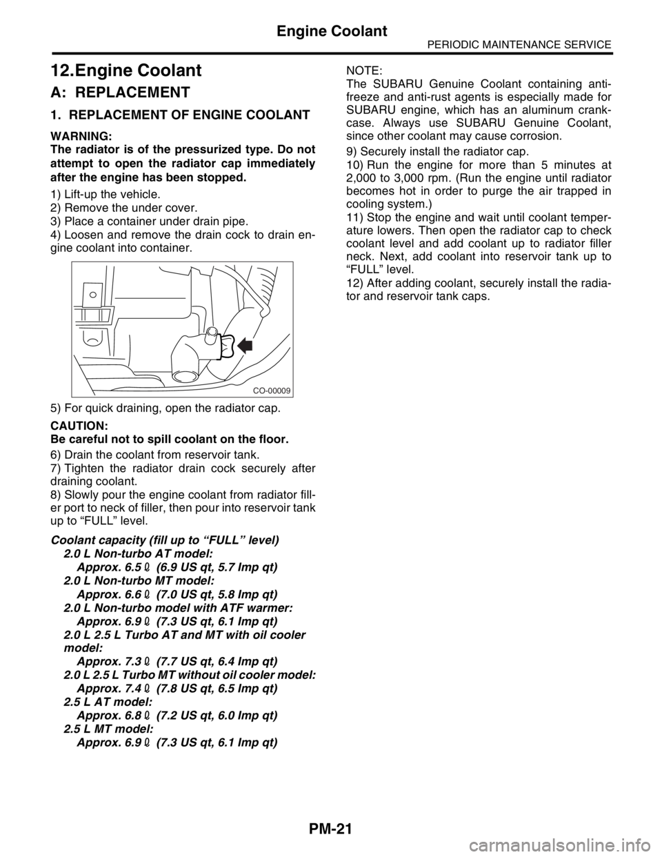
4) Loosen and remove the drain cock to drain en-
gine coolant into container.
5) For quick draining, open the radiator cap.
CAUTION:
Be careful not to spill coolant on the floor.
6) Drain the coolant from reservoir tank.
7) Tighten the radiator drain cock securely after
draining coolant.
8) Slowly pour the engine coolant from radiator fill-
er port to neck of filler, then pour into reservoir tank
up to “FULL” level.
Coolant capacity (fill up to “FULL” level)
2.0 L Non-turbo AT model:
Approx. 6.52 (6.9 US qt, 5.7 Imp qt)
2.0 L Non-turbo MT model:
Approx. 6.62 (7.0 US qt, 5.8 Imp qt)
2.0 L Non-turbo model with ATF warmer:
Approx. 6.92 (7.3 US qt, 6.1 Imp qt)
2.0 L 2.5 L Turbo AT and MT with oil cooler
model:
Approx. 7.32 (7.7 US qt, 6.4 Imp qt)
2.0 L 2.5 L Turbo MT without oil cooler model:
Approx. 7.42 (7.8 US qt, 6.5 Imp qt)
2.5 L AT model:
Approx. 6.82 (7.2 US qt, 6.0 Imp qt)
2.5 L MT model:
Approx. 6.92 (7.3 US qt, 6.1 Imp qt)NOTE:
The SUBARU Genuine Coolant containing anti-
freeze and anti-rust agents is especially made for
SUBARU engine, which has an aluminum crank-
case. Always use SUBARU Genuine Coolant,
since other coolant may cause corrosion.
9) Securely install the radiator cap.
10) Run the engine for more than 5 minutes at
2,000 to 3,000 rpm. (Run the engine until radiator
becomes hot in order to purge the air trapped in
cooling system.)
11) Stop the engine and wait until coolant temper-
ature lowers. Then open the radiator cap to check
coolant level and add coolant up to radiator filler
neck. Next, add coolant into reservoir tank up to
“FULL” level.
12) After adding coolant, securely install the radia-
tor and reservoir tank caps.
CO-00009
Page 763 of 2870
PM-26
PERIODIC MAINTENANCE SERVICE
ATF
16.ATF
A: INSPECTION
CAUTION:
The level of ATF varies with fluid temperature.
Pay attention to the fluid temperature when
checking ATF level.
1) Raise the ATF temperature by driving a distance
of 5 to 10 km (3 to 6 miles). Otherwise, idle the en-
gine to raise ATF temperature to 70 — 80°C (158
— 176°F) on Subaru Select Monitor.
TION, Subaru Select Monitor.>
2) Make sure the vehicle is level.
3) After selecting all positions (P, R, N, D, 3, 2, 1),
set the select lever in “P” range. Measure the ATF
level with the engine idling for one or two minutes.
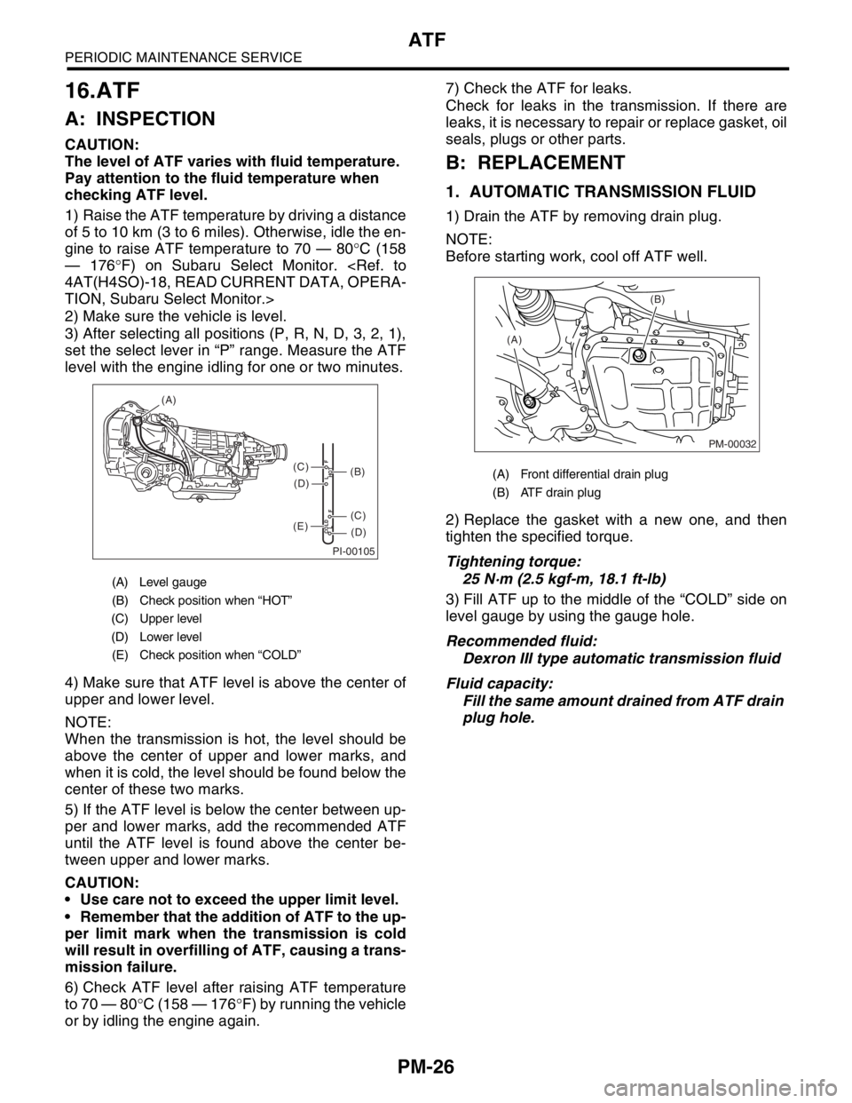
4) Make sure that ATF level is above the center of
upper and lower level.
NOTE:
When the transmission is hot, the level should be
above the center of upper and lower marks, and
when it is cold, the level should be found below the
center of these two marks.
5) If the ATF level is below the center between up-
per and lower marks, add the recommended ATF
until the ATF level is found above the center be-
tween upper and lower marks.
CAUTION:
Use care not to exceed the upper limit level.
Remember that the addition of ATF to the up-
per limit mark when the transmission is cold
will result in overfilling of ATF, causing a trans-
mission failure.
6) Check ATF level after raising ATF temperature
to 70 — 80°C (158 — 176°F) by running the vehicle
or by idling the engine again.7) Check the ATF for leaks.
Check for leaks in the transmission. If there are
leaks, it is necessary to repair or replace gasket, oil
seals, plugs or other parts.
B: REPLACEMENT
1. AUTOMATIC TRANSMISSION FLUID
1) Drain the ATF by removing drain plug.
NOTE:
Before starting work, cool off ATF well.
2) Replace the gasket with a new one, and then
tighten the specified torque.
Tightening torque:
25 N·m (2.5 kgf-m, 18.1 ft-lb)
3) Fill ATF up to the middle of the “COLD” side on
level gauge by using the gauge hole.
Recommended fluid:
Dexron III type automatic transmission fluid
Fluid capacity:
Fill the same amount drained from ATF drain
plug hole.
(A) Level gauge
(B) Check position when “HOT”
(C) Upper level
(D) Lower level
(E) Check position when “COLD”
PI-00105
COLD
LFHOT LF
(A)
(C)
(D)
(C)
(D)
(E)
(B)(A) Front differential drain plug
(B) ATF drain plug
PM-00032
(B)
(A)
Page 767 of 2870
PM-30
PERIODIC MAINTENANCE SERVICE
Brake Line
18.Brake Line
A: INSPECTION
1. BRAKE LINE
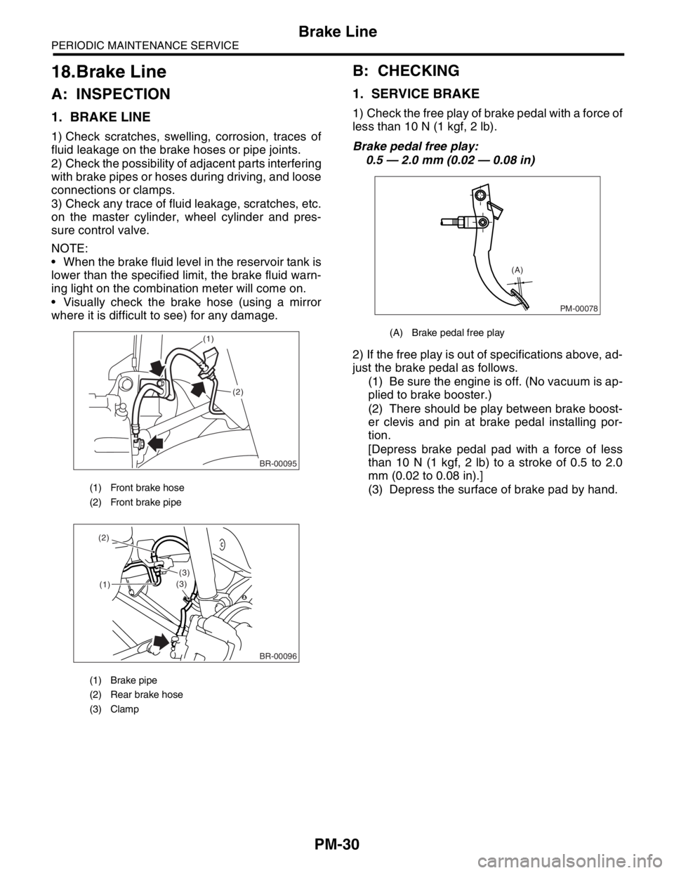
1) Check scratches, swelling, corrosion, traces of
fluid leakage on the brake hoses or pipe joints.
2) Check the possibility of adjacent parts interfering
with brake pipes or hoses during driving, and loose
connections or clamps.
3) Check any trace of fluid leakage, scratches, etc.
on the master cylinder, wheel cylinder and pres-
sure control valve.
NOTE:
When the brake fluid level in the reservoir tank is
lower than the specified limit, the brake fluid warn-
ing light on the combination meter will come on.
Visually check the brake hose (using a mirror
where it is difficult to see) for any damage.
B: CHECKING
1. SERVICE BRAKE
1) Check the free play of brake pedal with a force of
less than 10 N (1 kgf, 2 lb).
Brake pedal free play:
0.5 — 2.0 mm (0.02 — 0.08 in)
2) If the free play is out of specifications above, ad-
just the brake pedal as follows.
(1) Be sure the engine is off. (No vacuum is ap-
plied to brake booster.)
(2) There should be play between brake boost-
er clevis and pin at brake pedal installing por-
tion.
[Depress brake pedal pad with a force of less
than 10 N (1 kgf, 2 lb) to a stroke of 0.5 to 2.0
mm (0.02 to 0.08 in).]
(3) Depress the surface of brake pad by hand.
(1) Front brake hose
(2) Front brake pipe
(1) Brake pipe
(2) Rear brake hose
(3) Clamp
BR-00095
(1)
(2)
(1)
(3)
(3) (2)
BR-00096
(A) Brake pedal free play
PM-00078
(A)
Page 768 of 2870
PM-31
PERIODIC MAINTENANCE SERVICE
Brake Line
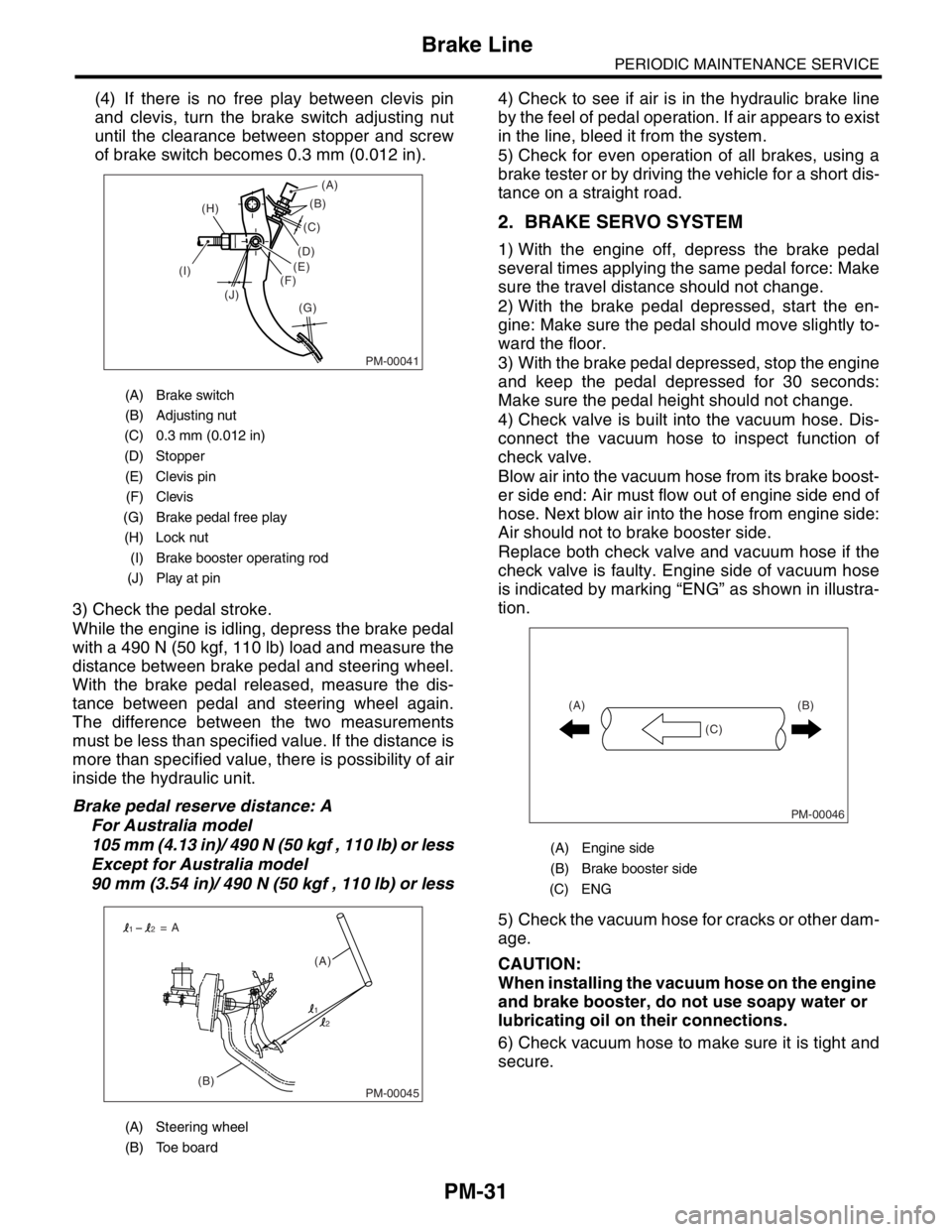
(4) If there is no free play between clevis pin
and clevis, turn the brake switch adjusting nut
until the clearance between stopper and screw
of brake switch becomes 0.3 mm (0.012 in).
3) Check the pedal stroke.
While the engine is idling, depress the brake pedal
with a 490 N (50 kgf, 110 lb) load and measure the
distance between brake pedal and steering wheel.
With the brake pedal released, measure the dis-
tance between pedal and steering wheel again.
The difference between the two measurements
must be less than specified value. If the distance is
more than specified value, there is possibility of air
inside the hydraulic unit.
Brake pedal reserve distance: A
For Australia model
105 mm (4.13 in)/ 490 N (50 kgf , 110 lb) or less
Except for Australia model
90 mm (3.54 in)/ 490 N (50 kgf , 110 lb) or less4) Check to see if air is in the hydraulic brake line
by the feel of pedal operation. If air appears to exist
in the line, bleed it from the system.
5) Check for even operation of all brakes, using a
brake tester or by driving the vehicle for a short dis-
tance on a straight road.
2. BRAKE SERVO SYSTEM
1) With the engine off, depress the brake pedal
several times applying the same pedal force: Make
sure the travel distance should not change.
2) With the brake pedal depressed, start the en-
gine: Make sure the pedal should move slightly to-
ward the floor.
3) With the brake pedal depressed, stop the engine
and keep the pedal depressed for 30 seconds:
Make sure the pedal height should not change.
4) Check valve is built into the vacuum hose. Dis-
connect the vacuum hose to inspect function of
check valve.
Blow air into the vacuum hose from its brake boost-
er side end: Air must flow out of engine side end of
hose. Next blow air into the hose from engine side:
Air should not to brake booster side.
Replace both check valve and vacuum hose if the
check valve is faulty. Engine side of vacuum hose
is indicated by marking “ENG” as shown in illustra-
tion.
5) Check the vacuum hose for cracks or other dam-
age.
CAUTION:
When installing the vacuum hose on the engine
and brake booster, do not use soapy water or
lubricating oil on their connections.
6) Check vacuum hose to make sure it is tight and
secure.
(A) Brake switch
(B) Adjusting nut
(C) 0.3 mm (0.012 in)
(D) Stopper
(E) Clevis pin
(F) Clevis
(G) Brake pedal free play
(H) Lock nut
(I) Brake booster operating rod
(J) Play at pin
(A) Steering wheel
(B) Toe board
PM-00041
(B)
(G) (H)
(I)
(J)(C)
(D)
(E)
(F)(A)
PM-00045(B)(A) = A
1
12
2
(A) Engine side
(B) Brake booster side
(C) ENG
PM-00046
(B)
(C) (A)
Page 779 of 2870
PM-42
PERIODIC MAINTENANCE SERVICE
Steering System (Power Steering)
(2) Retighten the adjusting screw to 7.4 N·m
(0.75 kgf-m, 5.4 ft-lb) and back off 25°.
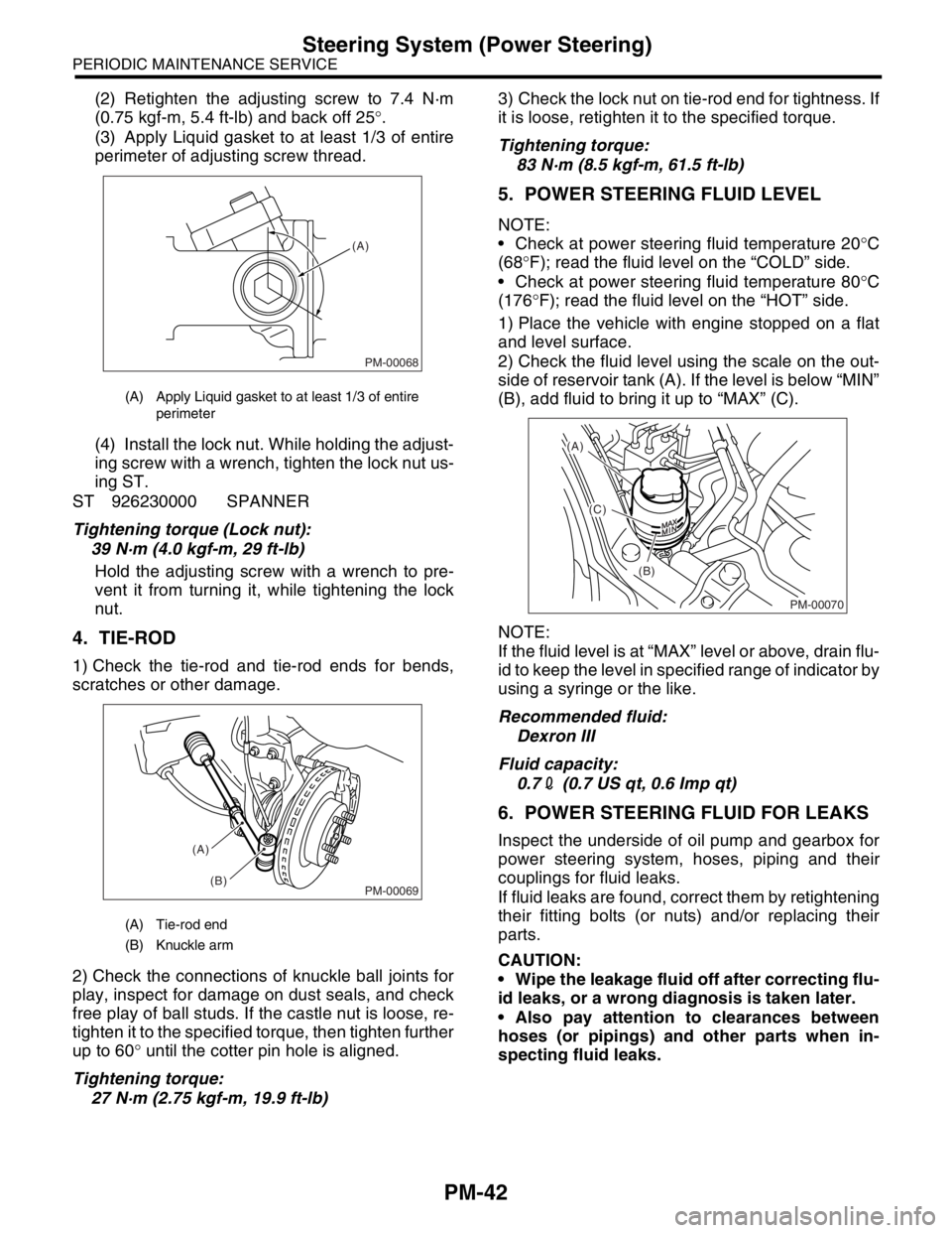
(3) Apply Liquid gasket to at least 1/3 of entire
perimeter of adjusting screw thread.
(4) Install the lock nut. While holding the adjust-
ing screw with a wrench, tighten the lock nut us-
ing ST.
ST 926230000 SPANNER
Tightening torque (Lock nut):
39 N·m (4.0 kgf-m, 29 ft-lb)
Hold the adjusting screw with a wrench to pre-
vent it from turning it, while tightening the lock
nut.
4. TIE-ROD
1) Check the tie-rod and tie-rod ends for bends,
scratches or other damage.
2) Check the connections of knuckle ball joints for
play, inspect for damage on dust seals, and check
free play of ball studs. If the castle nut is loose, re-
tighten it to the specified torque, then tighten further
up to 60° until the cotter pin hole is aligned.
Tightening torque:
27 N·m (2.75 kgf-m, 19.9 ft-lb)3) Check the lock nut on tie-rod end for tightness. If
it is loose, retighten it to the specified torque.
Tightening torque:
83 N·m (8.5 kgf-m, 61.5 ft-lb)
5. POWER STEERING FLUID LEVEL
NOTE:
Check at power steering fluid temperature 20°C
(68°F); read the fluid level on the “COLD” side.
Check at power steering fluid temperature 80°C
(176°F); read the fluid level on the “HOT” side.
1) Place the vehicle with engine stopped on a flat
and level surface.
2) Check the fluid level using the scale on the out-
side of reservoir tank (A). If the level is below “MIN”
(B), add fluid to bring it up to “MAX” (C).
NOTE:
If the fluid level is at “MAX” level or above, drain flu-
id to keep the level in specified range of indicator by
using a syringe or the like.
Recommended fluid:
Dexron III
Fluid capacity:
0.72 (0.7 US qt, 0.6 Imp qt)
6. POWER STEERING FLUID FOR LEAKS
Inspect the underside of oil pump and gearbox for
power steering system, hoses, piping and their
couplings for fluid leaks.
If fluid leaks are found, correct them by retightening
their fitting bolts (or nuts) and/or replacing their
parts.
CAUTION:
Wipe the leakage fluid off after correcting flu-
id leaks, or a wrong diagnosis is taken later.
Also pay attention to clearances between
hoses (or pipings) and other parts when in-
specting fluid leaks.
(A) Apply Liquid gasket to at least 1/3 of entire
perimeter
(A) Tie-rod end
(B) Knuckle arm
PM-00068
(A)
PM-00069
(A)
(B)
PM-00070
(A)
(C)
(B)
Page 780 of 2870
PM-43
PERIODIC MAINTENANCE SERVICE
Steering System (Power Steering)
7. HOSES OF OIL PUMP FOR DAMAGES
Check the pressure hose and return hose of oil
pump for crack, swell or damage. Replace the hose
with a new one if necessary.
CAUTION:
Prevent the hoses from revolving and/or turn-
ing when installing hoses.
8. POWER STEERING PIPES FOR DAM-
AGE
Check the power steering pipes for corrosion and
damage.
Replace the pipes with a new one if necessary.
9. GEARBOX BOOTS
Inspect both sides of gearbox boots as follows, and
correct the defects if necessary.
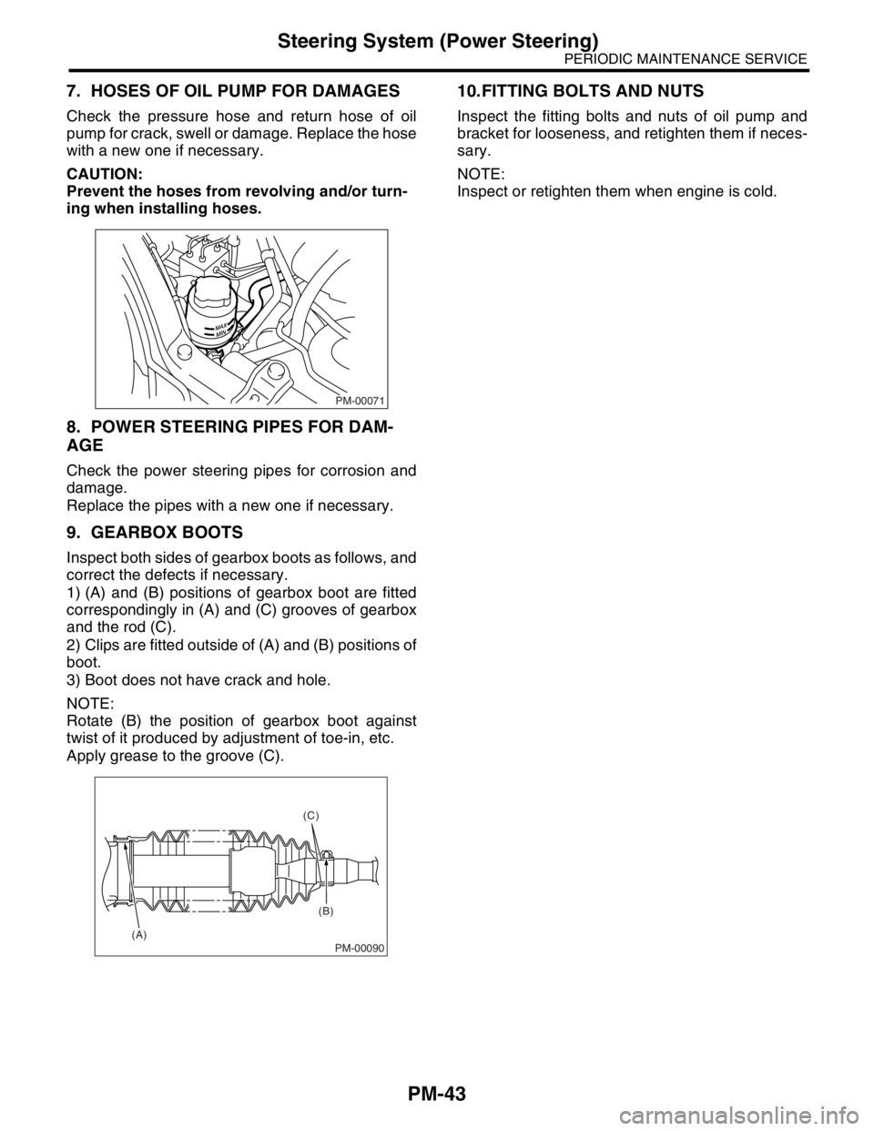
1) (A) and (B) positions of gearbox boot are fitted
correspondingly in (A) and (C) grooves of gearbox
and the rod (C).
2) Clips are fitted outside of (A) and (B) positions of
boot.
3) Boot does not have crack and hole.
NOTE:
Rotate (B) the position of gearbox boot against
twist of it produced by adjustment of toe-in, etc.
Apply grease to the groove (C).
10.FITTING BOLTS AND NUTS
Inspect the fitting bolts and nuts of oil pump and
bracket for looseness, and retighten them if neces-
sary.
NOTE:
Inspect or retighten them when engine is cold.
PM-00071
PM-00090
(C)
(B)
(A)
Page 812 of 2870
FU(H4SO)-30
FUEL INJECTION (FUEL SYSTEM)
Throttle Position Sensor
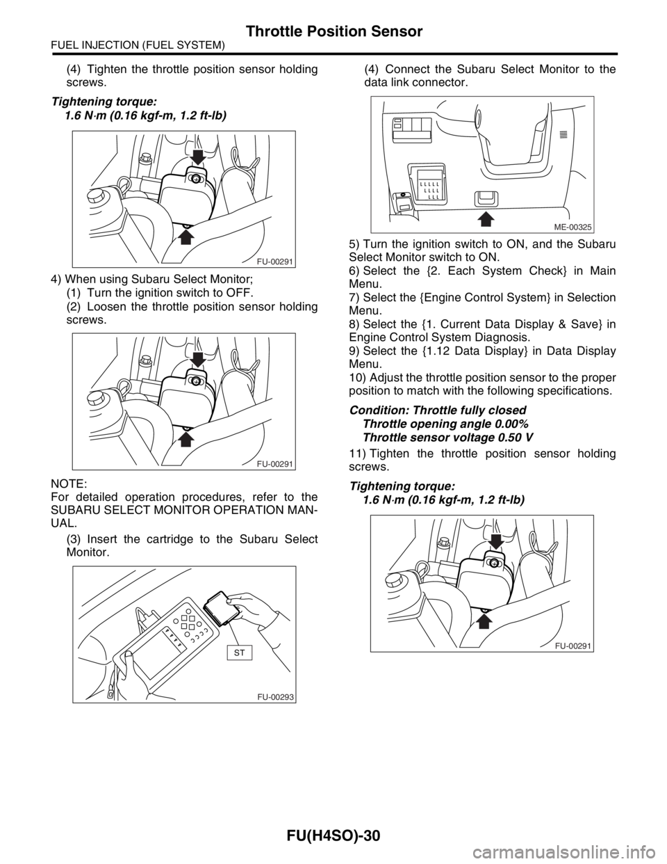
(4) Tighten the throttle position sensor holding
screws.
Tightening torque:
1.6 N
⋅m (0.16 kgf-m, 1.2 ft-lb)
4) When using Subaru Select Monitor;
(1) Turn the ignition switch to OFF.
(2) Loosen the throttle position sensor holding
screws.
NOTE:
For detailed operation procedures, refer to the
SUBARU SELECT MONITOR OPERATION MAN-
UAL.
(3) Insert the cartridge to the Subaru Select
Monitor.(4) Connect the Subaru Select Monitor to the
data link connector.
5) Turn the ignition switch to ON, and the Subaru
Select Monitor switch to ON.
6) Select the {2. Each System Check} in Main
Menu.
7) Select the {Engine Control System} in Selection
Menu.
8) Select the {1. Current Data Display & Save} in
Engine Control System Diagnosis.
9) Select the {1.12 Data Display} in Data Display
Menu.
10) Adjust the throttle position sensor to the proper
position to match with the following specifications.
Condition: Throttle fully closed
Throttle opening angle 0.00%
Throttle sensor voltage 0.50 V
11) Tighten the throttle position sensor holding
screws.
Tightening torque:
1.6 N
⋅m (0.16 kgf-m, 1.2 ft-lb)
FU-00291
FU-00291
FU-00293
ST
ME-00325
FU-00291
Page 884 of 2870
ME(H4SO)-15
MECHANICAL
General Description
C: CAUTION
Wear working clothing, including a cap, protec-
tive goggles and protective shoes during operation.
Remove contamination including dirt and corro-
sion before removal, installation or disassembly.
Keep the disassembled parts in order and pro-
tect them from dust or dirt.
Before removal, installation or disassembly, be
sure to clarify the failure. Avoid unnecessary re-
moval, installation, disassembly and replacement.
Be careful not to burn yourself, because each
part in the vehicle is hot after running.
Be sure to tighten bolts and nuts to the specified
torque.
Place shop jacks or rigid racks at the specified
points.
Before disconnecting electrical connectors of
sensors or units, be sure to disconnect the ground
cable from battery.
All parts should be thoroughly cleaned, paying
special attention to the engine oil passages, pis-
tons and bearings. Rotating parts and sliding parts such as piston,
bearing and gear should be coated with oil prior to
assembly.
Be careful not to let oil, grease or coolant contact
the timing belt, clutch disc and flywheel.
All removed parts, if to be reused, should be re-
installed in the original positions and directions.
Bolts, nuts and washers should be replaced with
new ones as required.
Even if necessary inspections have been made
in advance, proceed with assembly work while
making rechecks.
Remove or install engine in an area where chain
hoists, lifting devices, etc. are available for ready
use.
Be sure not to damage coated surfaces of body
panels with tools, or not to stain seats and windows
with coolant or oil. Place a cover over fenders, as
required, for protection.
Prior to starting work, prepare the following:
Service tools, clean cloth, containers to catch cool-
ant and oil, wire ropes, chain hoist, transmission
jacks, etc.
Lift-up or lower the vehicle when necessary.
Make sure to support the correct positions.
D: PREPARATION TOOL
1. SPECIAL TOOL
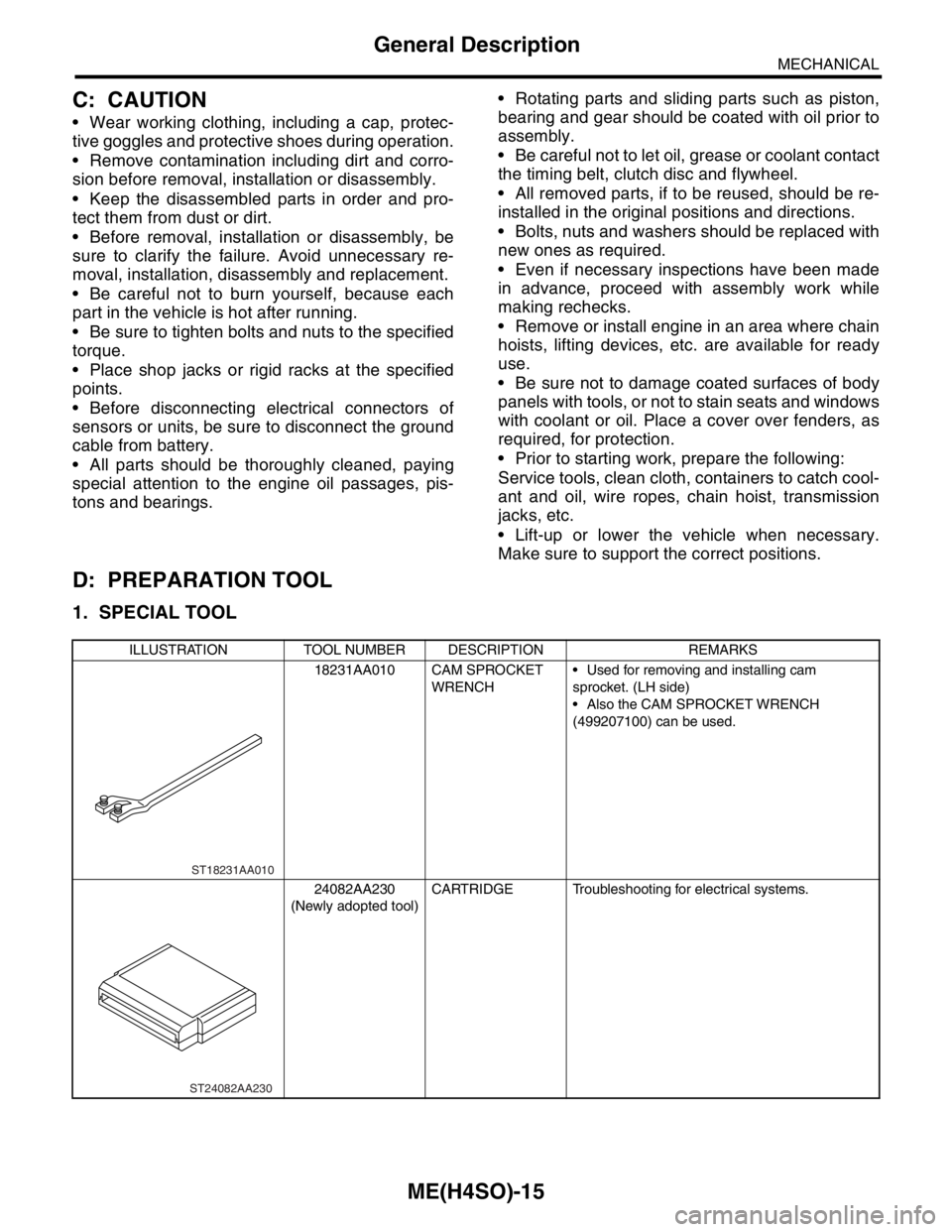
ILLUSTRATION TOOL NUMBER DESCRIPTION REMARKS
18231AA010 CAM SPROCKET
WRENCH Used for removing and installing cam
sprocket. (LH side)
Also the CAM SPROCKET WRENCH
(499207100) can be used.
24082AA230
(Newly adopted tool)CARTRIDGE Troubleshooting for electrical systems.
ST18231AA010
ST24082AA230