Page 1052 of 2870

LU(H4SO)-24
LUBRICATION
Engine Lubrication System Trouble in General
9. Engine Lubrication System Trouble in General
A: INSPECTION
Before performing diagnostics, make sure that the engine oil level is correct and no oil leakage exists.
Trouble Possible cause Corrective action
1. Warning light remains
on.1) Oil pressure switch
failureCracked diaphragm or oil leakage within switch Replace.
Broken spring or seized contacts Replace.
2) Low oil pressureClogged oil filter Replace.
Malfunction of oil by-pass valve of oil filter Clean or replace.
Malfunction of oil relief valve of oil pump Clean or replace.
Clogged oil passage Clean.
Excessive tip clearance and side clearance of oil
pump rotor and gearReplace.
Clogged oil strainer or broken pipe Clean or replace.
3) No oil pressureInsufficient engine oil Replenish.
Broken pipe of oil strainer Replace.
Stuck oil pump rotor Replace.
2. Warning light does
not go on.1) Malfunction of combination meter Replace.
2) Poor contact of switch contact points Replace.
3) Disconnection of wiring Repair.
3. Warning light flickers
momentarily.1) Poor contact at terminals Repair.
2) Defective wiring harness Repair.
3) Low oil pressureCheck for the same
possible causes as
listed in 1. — 2).
Page 1101 of 2870
EN(H4SO)-3
ENGINE (DIAGNOSTIC)
Basic Diagnostics Procedure
2. AUTOMATIC TRANSMISSION
When the DTC about automatic transmission is
shown on display, carry out the following basic
check. After that, carry out the replacement or re-
pair work.
1) ATF level check
Transmission Fluid.>
2) Differential gear oil level check
Differential Gear Oil.>
3) ATF leak check
Transmission Fluid.>
4) Differential gear oil level check
Differential Gear Oil.>
5) Stall Test
6) Line Pressure Test
sure Test.>
7) Transfer Clutch Pressure Test
Transfer Clutch Pressure Test.>
8) Time Lag Test
9) Road Test
10) Shift characteristics
Clutch Pressure Test.>
Page 1103 of 2870

EN(H4SO)-5
ENGINE (DIAGNOSTIC)
Check List for Interview
2. CHECK LIST No. 2
Check the following items about the vehicle’s state when malfunction indicator light turns on.
NOTE:
Use copies of this page for interviewing customers.
a) Other warning lights or indicators turn on. ❏ Yes / ❏ No
❏ Low fuel warning light
❏ Charge indicator light
❏ AT diagnostic indicator light
❏ ABS Warning light
❏ Oil pressure indicator light
b) Fuel level
Lack of gasoline: ❏ Yes / ❏ No
Indicator position of fuel gauge:
Experienced running out of fuel: ❏ Ye s / ❏ No
c) Intentional connecting or disconnecting of harness connectors or spark plug cords: ❏ Yes / ❏ No
What:
d) Intentional connecting or disconnecting of hoses: ❏ Ye s / ❏ No
What:
e) Installing of other parts except genuine parts: ❏ Ye s / ❏ No
What:
Where:
f) Occurrence of noise: ❏ Yes / ❏ No
From where:
What kind:
g) Occurrence of smell: ❏ Yes / ❏ No
From where:
What kind:
h) Intrusion of water into engine compartment or passenger compartment: ❏ Yes / ❏ No
i) Troubles occurred
❏ Engine does not start.
❏ Engine stalls during idling.
❏ Engine stalls while driving.
❏ Engine speed decreases.
❏ Engine speed does not decrease.
❏ Rough idling
❏ Poor acceleration
❏ Back fire
❏ After fire
❏ Does not shift.
❏ Excessive shift shock
Page 1473 of 2870
ME(H4DOTC)-17
MECHANICAL
General Description
(1) Oil pressure switch (15) AdapterTightening torque: N⋅m (kgf-m, ft-lb)
(2) Cylinder block (RH) (16) Oil coolerT1: 5 (0.5, 3.6)
(3) Service hole plug (17) Waster by-pass pipe T2: 6.4 (0.65, 4.7)
(4) Gasket (18) ConnectorT3: 10 (1.0, 7.2)
(5) Oil separator cover (19) Oil strainerT4: 25 (2.5, 18.1)
(6) Water by-pass pipe (20) GasketT5:
INSTALLATION, CYLINDER
BLOCK.> (7) Oil pump (21) Oil pan
(8) Front oil seal (22) Drain plug
(9) Rear oil seal (23) Metal gasketT6: 70 (7.1, 50.6)
(10) O-ring (24) Oil level gauge guideT7: First 12 (1.2, 8.7)
Second 12 (1.2, 8.7)
(11) Service hole cover (25) Oil filter
(12) Cylinder block (LH) (26) GasketT8: 16 (1.6, 11.6)
(13) Water pump (27) Water pump hoseT9: 44 (4.5, 33)
(14) Baffle plate (28) PlugT10: 25 (2.5, 18.1)
T11: 54 (5.3, 39)
T12: 45 (4.6, 33)
Page 1526 of 2870

ME(H4DOTC)-68
MECHANICAL
Camshaft
18.Camshaft
A: REMOVAL
1) Remove the V-belt.
INSTALLATION, V-belt.>
2) Remove the crank pulley.
55, REMOVAL, Crank Pulley.>
3) Remove the timing belt cover.
ME(H4DOTC)-57, REMOVAL, Timing Belt Cover.>
4) Remove the timing belt assembly.
ME(H4DOTC)-58, REMOVAL, Timing Belt Assem-
bly.>
5) Remove the cam sprocket.
ME(H4DOTC)-67, REMOVAL, Cam Sprocket.>
6) Remove the crank sprocket.
ME(H4DOTC)-68, REMOVAL, Crank Sprocket.>
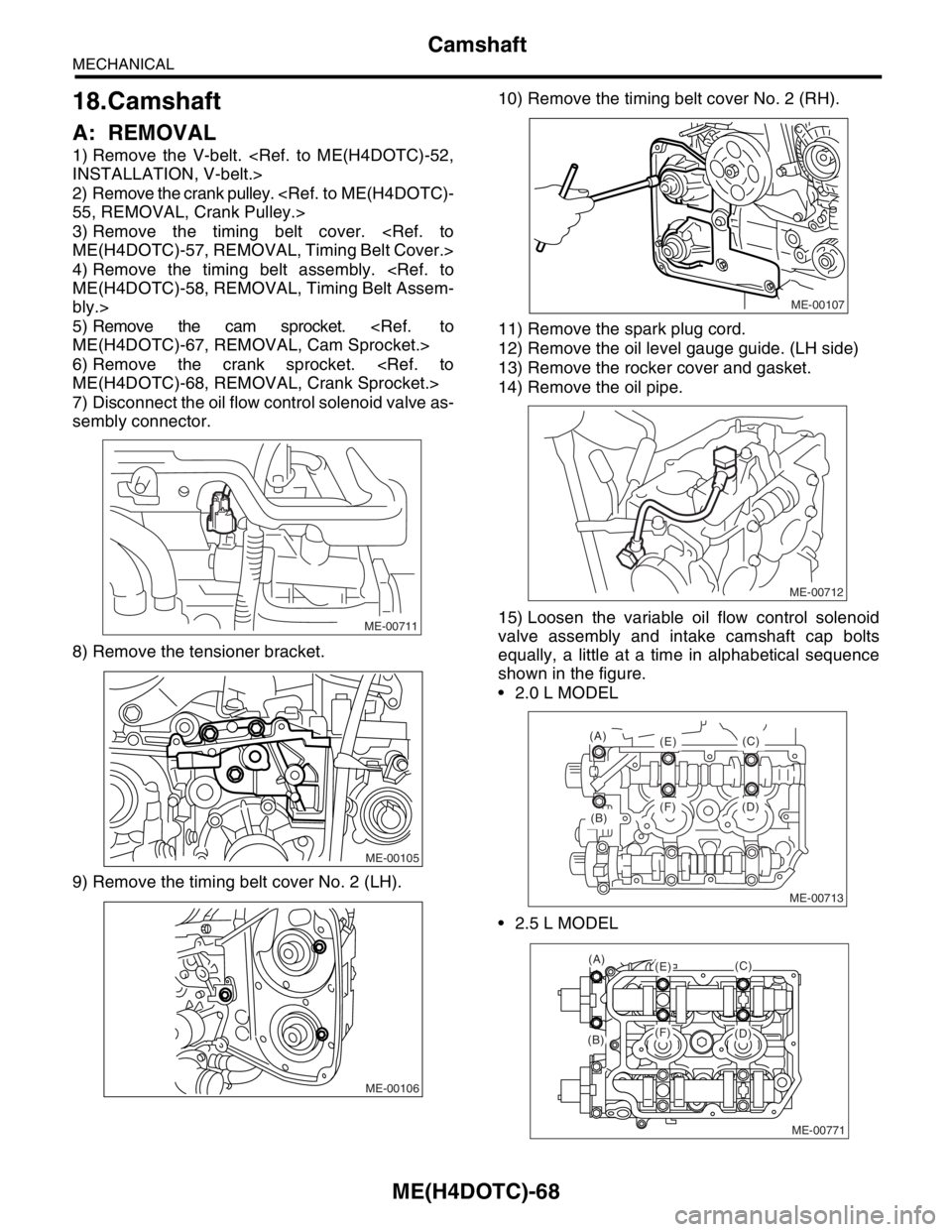
7) Disconnect the oil flow control solenoid valve as-
sembly connector.
8) Remove the tensioner bracket.
9) Remove the timing belt cover No. 2 (LH).10) Remove the timing belt cover No. 2 (RH).
11) Remove the spark plug cord.
12) Remove the oil level gauge guide. (LH side)
13) Remove the rocker cover and gasket.
14) Remove the oil pipe.
15) Loosen the variable oil flow control solenoid
valve assembly and intake camshaft cap bolts
equally, a little at a time in alphabetical sequence
shown in the figure.
2.0 L MODEL
2.5 L MODEL
ME-00711
ME-00105
ME-00106
ME-00107
ME-00712
ME-00713
(B)
(A)
(E)
(F) (D)(C)
ME-00771
(A)(E)
(F)(B)(D)
(C)
Page 1555 of 2870

ME(H4DOTC)-95
MECHANICAL
Cylinder Block
33) Install the oil filter using ST.
LU(H4SO)-23, INSTALLATION, Engine Oil Filter.>
34) Install the water by-pass pipe between oil cool-
er and water pump.
35) Install the water pipe.
NOTE:
Always use a new O-ring.
36) Install the cylinder head assembly.
ME(H4DOTC)-76, INSTALLATION, Cylinder Head
Assembly.>
37) Install the oil level gauge guide and tighten the
attaching bolt (LH side).
38) Install the rocker cover.
39) Install the crank sprocket.
ME(H4DOTC)-68, INSTALLATION, Crank Sprock-
et.>40) Install the cam sprocket.
ME(H4DOTC)-67, INSTALLATION, Cam Sprock-
et.>
41) Install the timing belt assembly.
ME(H4DOTC)-60, INSTALLATION, Timing Belt
Assembly.>
42) Install the timing belt cover.
ME(H4DOTC)-57, INSTALLATION, Timing Belt
Cover.>
43) Install the crank pulley.
55, INSTALLATION, Crank Pulley.>
44) Install the generator and A/C compressor
brackets on cylinder head.
45) Install the V-belt.
INSTALLATION, V-belt.>
46) Install the intake manifold.
FU(H4DOTC)-17, INSTALLATION, Intake Mani-
fold.>
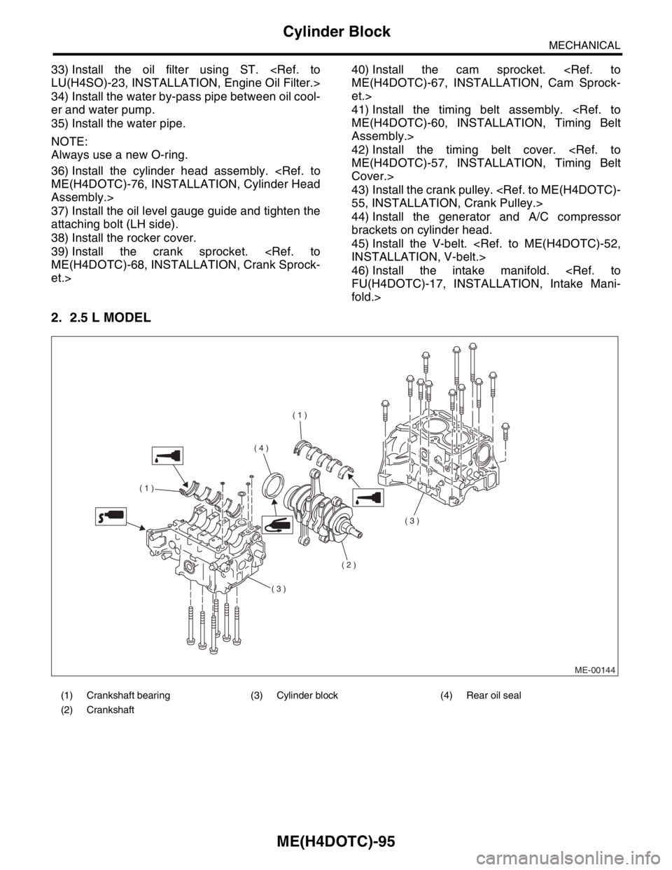
2. 2.5 L MODEL
(1) Crankshaft bearing (3) Cylinder block (4) Rear oil seal
(2) Crankshaft
ME-00144
( 1 )
( 1 )
( 2 )
( 3 )
( 3 )
( 4 )
Page 1563 of 2870

ME(H4DOTC)-103
MECHANICAL
Cylinder Block
NOTE:
Be sure to use a new gasket.
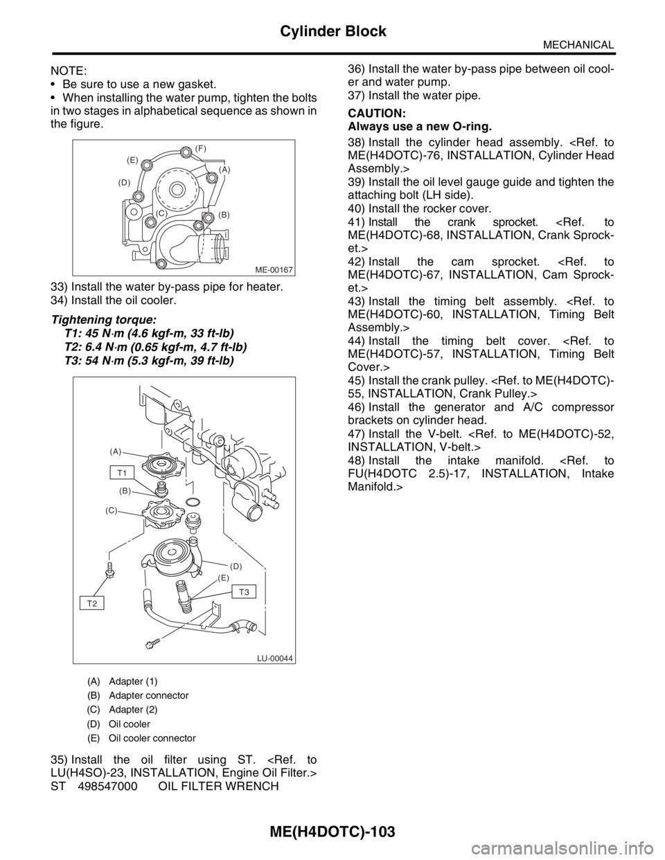
When installing the water pump, tighten the bolts
in two stages in alphabetical sequence as shown in
the figure.
33) Install the water by-pass pipe for heater.
34) Install the oil cooler.
Tightening torque:
T1: 45 N
⋅m (4.6 kgf-m, 33 ft-lb)
T2: 6.4 N
⋅m (0.65 kgf-m, 4.7 ft-lb)
T3: 54 N
⋅m (5.3 kgf-m, 39 ft-lb)
35) Install the oil filter using ST.
LU(H4SO)-23, INSTALLATION, Engine Oil Filter.>
ST 498547000 OIL FILTER WRENCH36) Install the water by-pass pipe between oil cool-
er and water pump.
37) Install the water pipe.
CAUTION:
Always use a new O-ring.
38) Install the cylinder head assembly.
ME(H4DOTC)-76, INSTALLATION, Cylinder Head
Assembly.>
39) Install the oil level gauge guide and tighten the
attaching bolt (LH side).
40) Install the rocker cover.
41) Install the crank sprocket.
ME(H4DOTC)-68, INSTALLATION, Crank Sprock-
et.>
42) Install the cam sprocket.
ME(H4DOTC)-67, INSTALLATION, Cam Sprock-
et.>
43) Install the timing belt assembly.
ME(H4DOTC)-60, INSTALLATION, Timing Belt
Assembly.>
44) Install the timing belt cover.
ME(H4DOTC)-57, INSTALLATION, Timing Belt
Cover.>
45) Install the crank pulley.
55, INSTALLATION, Crank Pulley.>
46) Install the generator and A/C compressor
brackets on cylinder head.
47) Install the V-belt.
INSTALLATION, V-belt.>
48) Install the intake manifold.
FU(H4DOTC 2.5)-17, INSTALLATION, Intake
Manifold.>
(A) Adapter (1)
(B) Adapter connector
(C) Adapter (2)
(D) Oil cooler
(E) Oil cooler connector
ME-00167
(B) (C) (D)(E)(F)
(A)
LU-00044
(A)
(B)
(C)
(D)
(E)
T1
T2
T3
Page 1633 of 2870
EN(H4DOTC)-3
ENGINE (DIAGNOSTIC)
Basic Diagnostics Procedure
2. AUTOMATIC TRANSMISSION
When the DTC about automatic transmission is
shown on display, carry out the following basic
check.After that, carry out the replacement or re-
pair work.
1) ATF level check
Transmission Fluid.>
2) Differential gear oil level check
Differential Gear Oil.>
3) ATF leak check
Transmission Fluid.>
4) Differential gear oil leak check
Differential Gear Oil.>
5) Stall Test
6) Line Pressure Test
sure Test.>
7) Transfer Clutch Pressure Test
Transfer Clutch Pressure Test.>
8) Time Lag Test
9) Road Test
10) Shift characteristics
Clutch Pressure Test.>