2004 SUBARU FORESTER oil level
[x] Cancel search: oil levelPage 761 of 2870

PM-24
PERIODIC MAINTENANCE SERVICE
Transmission Gear Oil
14.Transmission Gear Oil
A: REPLACEMENT
1. MANUAL TRANSMISSION
1) Drain the gear oil by removing drain plug.
CAUTION:
Before starting work, cool off the transmis-
sion gear oil well.
If transmission gear oil adheres to the ex-
haust pipe, wipe it off completely.
2) Replace the gasket with new one, and then tight-
en it to the specified torque.
Tightening torque:
70 N·m (7.1 kgf-m, 51.6 ft-lb)
3) Fill transmission gear oil through the oil level
gauge hole up to the upper point of level gauge.
CAUTION:
Each oil manufacturer has its base oil and addi-
tives. Thus, do not mix two or more brands.
Gear oil capacity:
Non-turbo model
4.02 (4.2 US qt, 3.5 Imp qt)
Turbo model
Without oil pump
3.52 (3.7 US qt, 3.1 Imp qt)
With oil pump
3.92 (4.1 US qt, 3.4 Imp qt)
(A) Oil level gauge
(B) Upper level
(C) Lower level
PM-00029
PM-00030
(B)
(C) (A)
Page 763 of 2870
PM-26
PERIODIC MAINTENANCE SERVICE
ATF
16.ATF
A: INSPECTION
CAUTION:
The level of ATF varies with fluid temperature.
Pay attention to the fluid temperature when
checking ATF level.
1) Raise the ATF temperature by driving a distance
of 5 to 10 km (3 to 6 miles). Otherwise, idle the en-
gine to raise ATF temperature to 70 — 80°C (158
— 176°F) on Subaru Select Monitor.
TION, Subaru Select Monitor.>
2) Make sure the vehicle is level.
3) After selecting all positions (P, R, N, D, 3, 2, 1),
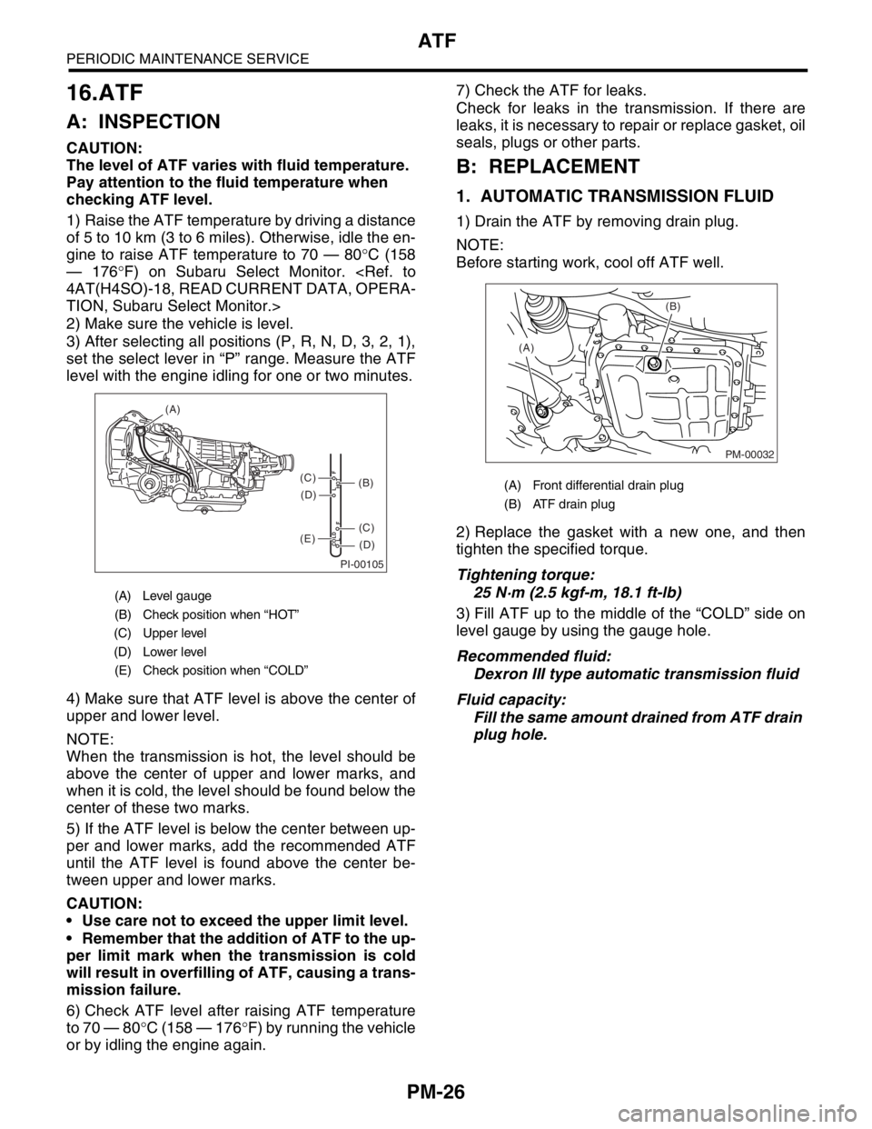
set the select lever in “P” range. Measure the ATF
level with the engine idling for one or two minutes.
4) Make sure that ATF level is above the center of
upper and lower level.
NOTE:
When the transmission is hot, the level should be
above the center of upper and lower marks, and
when it is cold, the level should be found below the
center of these two marks.
5) If the ATF level is below the center between up-
per and lower marks, add the recommended ATF
until the ATF level is found above the center be-
tween upper and lower marks.
CAUTION:
Use care not to exceed the upper limit level.
Remember that the addition of ATF to the up-
per limit mark when the transmission is cold
will result in overfilling of ATF, causing a trans-
mission failure.
6) Check ATF level after raising ATF temperature
to 70 — 80°C (158 — 176°F) by running the vehicle
or by idling the engine again.7) Check the ATF for leaks.
Check for leaks in the transmission. If there are
leaks, it is necessary to repair or replace gasket, oil
seals, plugs or other parts.
B: REPLACEMENT
1. AUTOMATIC TRANSMISSION FLUID
1) Drain the ATF by removing drain plug.
NOTE:
Before starting work, cool off ATF well.
2) Replace the gasket with a new one, and then
tighten the specified torque.
Tightening torque:
25 N·m (2.5 kgf-m, 18.1 ft-lb)
3) Fill ATF up to the middle of the “COLD” side on
level gauge by using the gauge hole.
Recommended fluid:
Dexron III type automatic transmission fluid
Fluid capacity:
Fill the same amount drained from ATF drain
plug hole.
(A) Level gauge
(B) Check position when “HOT”
(C) Upper level
(D) Lower level
(E) Check position when “COLD”
PI-00105
COLD
LFHOT LF
(A)
(C)
(D)
(C)
(D)
(E)
(B)(A) Front differential drain plug
(B) ATF drain plug
PM-00032
(B)
(A)
Page 765 of 2870
PM-28
PERIODIC MAINTENANCE SERVICE
Front & Rear Differential Oil
17.Front & Rear Differential Oil
A: REPLACEMENT
1. FRONT DIFFERENTIAL (MT MODEL)
For MT model, manual transmission oil works as
differential oil to lubricate differential. Refer to
“Transmission Oil”.
2. FRONT DIFFERENTIAL (AT MODEL)
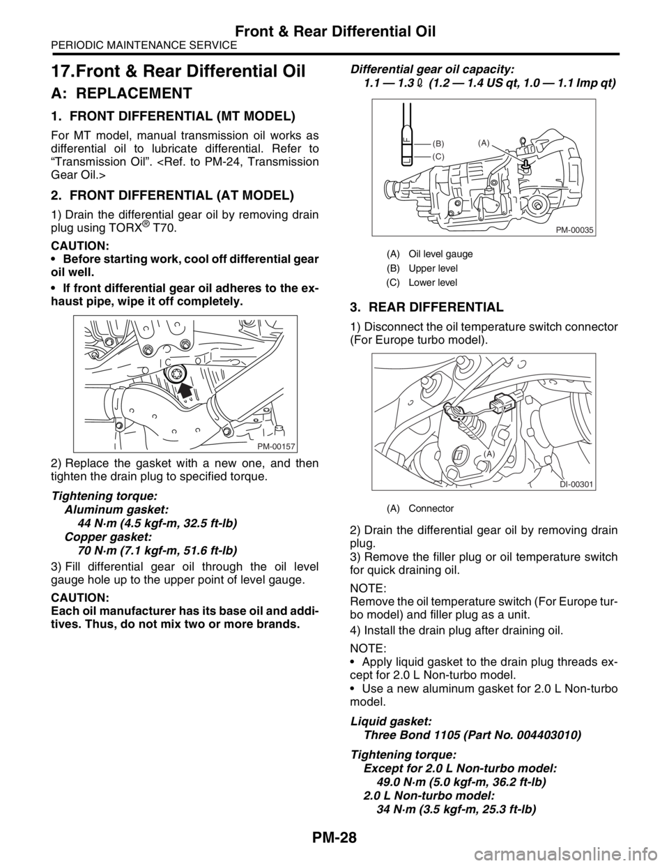
1) Drain the differential gear oil by removing drain
plug using TORX® T70.
CAUTION:
Before starting work, cool off differential gear
oil well.
If front differential gear oil adheres to the ex-
haust pipe, wipe it off completely.
2) Replace the gasket with a new one, and then
tighten the drain plug to specified torque.
Tightening torque:
Aluminum gasket:
44 N·m (4.5 kgf-m, 32.5 ft-lb)
Copper gasket:
70 N·m (7.1 kgf-m, 51.6 ft-lb)
3) Fill differential gear oil through the oil level
gauge hole up to the upper point of level gauge.
CAUTION:
Each oil manufacturer has its base oil and addi-
tives. Thus, do not mix two or more brands.Differential gear oil capacity:
1.1 — 1.32 (1.2 — 1.4 US qt, 1.0 — 1.1 Imp qt)
3. REAR DIFFERENTIAL
1) Disconnect the oil temperature switch connector
(For Europe turbo model).
2) Drain the differential gear oil by removing drain
plug.
3) Remove the filler plug or oil temperature switch
for quick draining oil.
NOTE:
Remove the oil temperature switch (For Europe tur-
bo model) and filler plug as a unit.
4) Install the drain plug after draining oil.
NOTE:
Apply liquid gasket to the drain plug threads ex-
cept for 2.0 L Non-turbo model.
Use a new aluminum gasket for 2.0 L Non-turbo
model.
Liquid gasket:
Three Bond 1105 (Part No. 004403010)
Tightening torque:
Except for 2.0 L Non-turbo model:
49.0 N·m (5.0 kgf-m, 36.2 ft-lb)
2.0 L Non-turbo model:
34 N·m (3.5 kgf-m, 25.3 ft-lb)
PM-00157
(A) Oil level gauge
(B) Upper level
(C) Lower level
(A) Connector
PM-00035
(B)
(C)(A)
DI-00301
(A)
Page 779 of 2870
PM-42
PERIODIC MAINTENANCE SERVICE
Steering System (Power Steering)
(2) Retighten the adjusting screw to 7.4 N·m
(0.75 kgf-m, 5.4 ft-lb) and back off 25°.
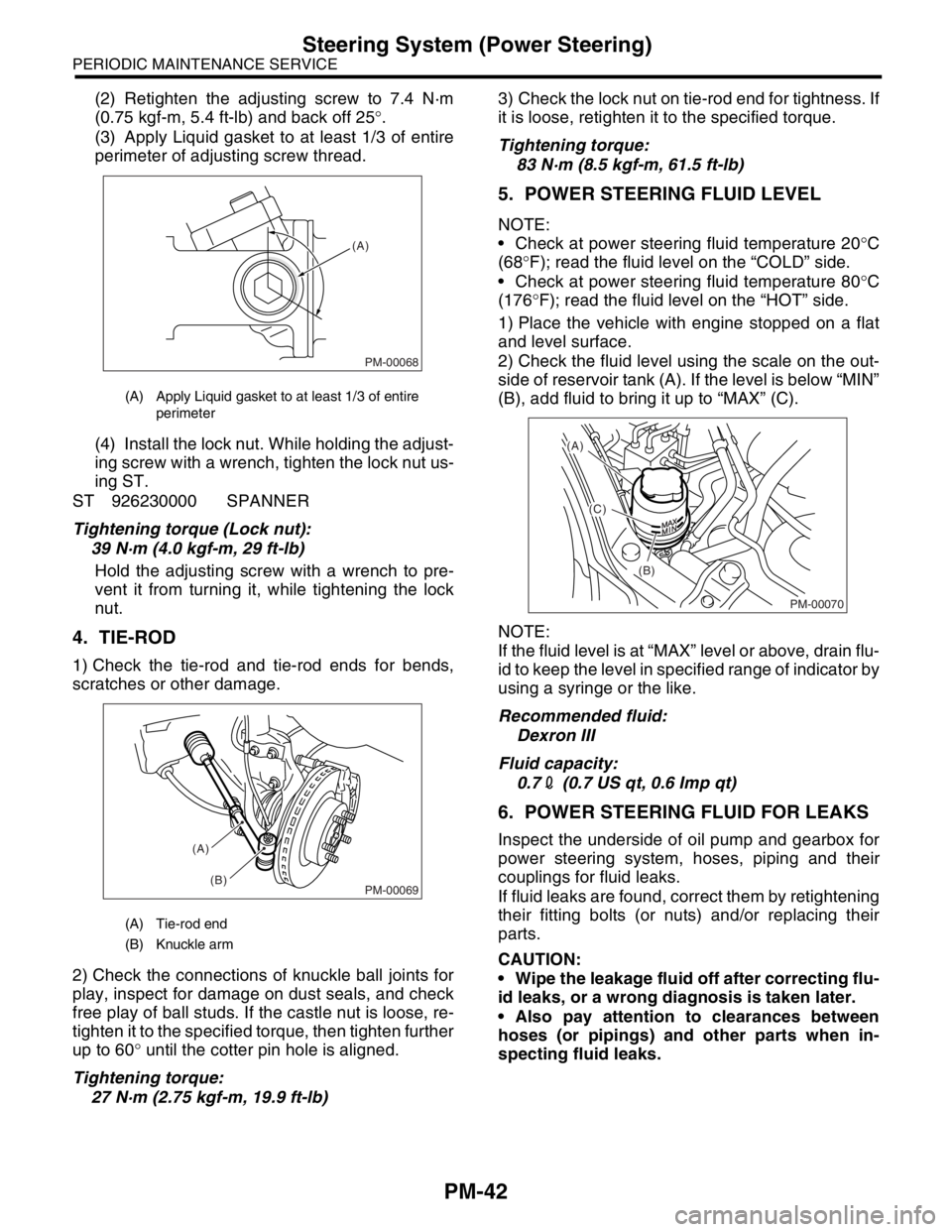
(3) Apply Liquid gasket to at least 1/3 of entire
perimeter of adjusting screw thread.
(4) Install the lock nut. While holding the adjust-
ing screw with a wrench, tighten the lock nut us-
ing ST.
ST 926230000 SPANNER
Tightening torque (Lock nut):
39 N·m (4.0 kgf-m, 29 ft-lb)
Hold the adjusting screw with a wrench to pre-
vent it from turning it, while tightening the lock
nut.
4. TIE-ROD
1) Check the tie-rod and tie-rod ends for bends,
scratches or other damage.
2) Check the connections of knuckle ball joints for
play, inspect for damage on dust seals, and check
free play of ball studs. If the castle nut is loose, re-
tighten it to the specified torque, then tighten further
up to 60° until the cotter pin hole is aligned.
Tightening torque:
27 N·m (2.75 kgf-m, 19.9 ft-lb)3) Check the lock nut on tie-rod end for tightness. If
it is loose, retighten it to the specified torque.
Tightening torque:
83 N·m (8.5 kgf-m, 61.5 ft-lb)
5. POWER STEERING FLUID LEVEL
NOTE:
Check at power steering fluid temperature 20°C
(68°F); read the fluid level on the “COLD” side.
Check at power steering fluid temperature 80°C
(176°F); read the fluid level on the “HOT” side.
1) Place the vehicle with engine stopped on a flat
and level surface.
2) Check the fluid level using the scale on the out-
side of reservoir tank (A). If the level is below “MIN”
(B), add fluid to bring it up to “MAX” (C).
NOTE:
If the fluid level is at “MAX” level or above, drain flu-
id to keep the level in specified range of indicator by
using a syringe or the like.
Recommended fluid:
Dexron III
Fluid capacity:
0.72 (0.7 US qt, 0.6 Imp qt)
6. POWER STEERING FLUID FOR LEAKS
Inspect the underside of oil pump and gearbox for
power steering system, hoses, piping and their
couplings for fluid leaks.
If fluid leaks are found, correct them by retightening
their fitting bolts (or nuts) and/or replacing their
parts.
CAUTION:
Wipe the leakage fluid off after correcting flu-
id leaks, or a wrong diagnosis is taken later.
Also pay attention to clearances between
hoses (or pipings) and other parts when in-
specting fluid leaks.
(A) Apply Liquid gasket to at least 1/3 of entire
perimeter
(A) Tie-rod end
(B) Knuckle arm
PM-00068
(A)
PM-00069
(A)
(B)
PM-00070
(A)
(C)
(B)
Page 879 of 2870
ME(H4SO)-10
MECHANICAL
General Description
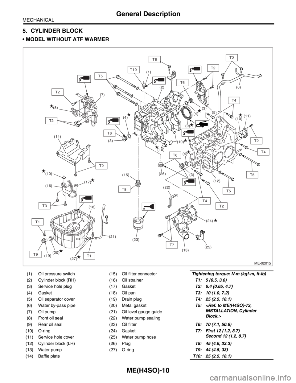
5. CYLINDER BLOCK
MODEL WITHOUT ATF WARMER
(1) Oil pressure switch (15) Oil filter connectorTightening torque: N⋅m (kgf-m, ft-lb)
(2) Cylinder block (RH) (16) Oil strainerT1: 5 (0.5, 3.6)
(3) Service hole plug (17) GasketT2: 6.4 (0.65, 4.7)
(4) Gasket (18) Oil panT3: 10 (1.0, 7.2)
(5) Oil separator cover (19) Drain plugT4: 25 (2.5, 18.1)
(6) Water by-pass pipe (20) Metal gasketT5:
Block.> (7) Oil pump (21) Oil level gauge guide
(8) Front oil seal (22) Water pump sealing
(9) Rear oil seal (23) Oil filterT6: 70 (7.1, 50.6)
(10) O-ring (24) GasketT7: First 12 (1.2, 8.7)
Second 12 (1.2, 8.7)
(11) Service hole cover (25) Water pump hose
(12) Cylinder block (LH) (26) PlugT8: 45 (4.6, 33.3)
(13) Water pump (27) O-ringT9: 44 (4.5, 33)
(14) Baffle plateT10: 25 (2.5, 18.1)
ME-02015
(14)
T6
T7
T2
T2
T4
T8
T4
T5
T2
T6
T6
T10
T1
T2
T8
T1
T3
T9
T2
T2
(9) (8)(7)(6)
(10)
(10)
(10)
(26)
(22)(11)
(12)
(13)
(19)(18)
(20)(17)
(16)
(24) (10)
(25)(5)
(4)
(4)
(4)(3)
(3)
(3) (2) (1)
(21)(15)
(23)
T5
T2
T5
T4
(27)
Page 880 of 2870
ME(H4SO)-11
MECHANICAL
General Description
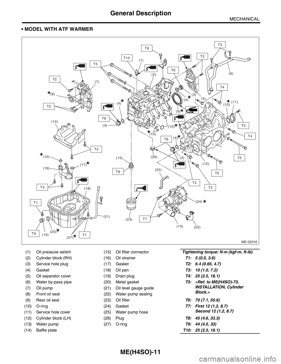
MODEL WITH ATF WARMER
(1) Oil pressure switch (15) Oil filter connectorTightening torque: N⋅m (kgf-m, ft-lb)
(2) Cylinder block (RH) (16) Oil strainerT1: 5 (0.5, 3.6)
(3) Service hole plug (17) GasketT2: 6.4 (0.65, 4.7)
(4) Gasket (18) Oil panT3: 10 (1.0, 7.2)
(5) Oil separator cover (19) Drain plugT4: 25 (2.5, 18.1)
(6) Water by-pass pipe (20) Metal gasketT5:
Block.> (7) Oil pump (21) Oil level gauge guide
(8) Front oil seal (22) Water pump sealing
(9) Rear oil seal (23) Oil filterT6: 70 (7.1, 50.6)
(10) O-ring (24) GasketT7: First 12 (1.2, 8.7)
Second 12 (1.2, 8.7)
(11) Service hole cover (25) Water pump hose
(12) Cylinder block (LH) (26) PlugT8: 45 (4.6, 33.3)
(13) Water pump (27) O-ringT9: 44 (4.5, 33)
(14) Baffle plateT10: 25 (2.5, 18.1)
ME-02016
(14)
T6
T2
T2
T4
T8
T5
T2
T6
T6
T10
T1
T2
T8
T1
T3
T9
T2
T2
(9) (8)(7)
(10)
(10)
(10)
(26)
(22)(11)
(12)
(19)(18)
(20)(17)
(16)
(24) (10)
(25)(5)
(4)
(4)
(4)(3)
(3)
(3) (2) (1)
(21)(15)
(23)
T5
T2
T5
T4
(27)
T7
(13)
(6)
T4
Page 907 of 2870
ME(H4SO)-38
MECHANICAL
Engine Assembly
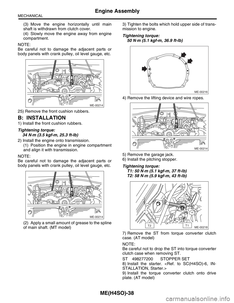
(3) Move the engine horizontally until main
shaft is withdrawn from clutch cover.
(4) Slowly move the engine away from engine
compartment.
NOTE:
Be careful not to damage the adjacent parts or
body panels with crank pulley, oil level gauge, etc.
25) Remove the front cushion rubbers.
B: INSTALLATION
1) Install the front cushion rubbers.
Tightening torque:
34 N
⋅m (3.5 kgf-m, 25.3 ft-lb)
2) Install the engine onto transmission.
(1) Position the engine in engine compartment
and align it with transmission.
NOTE:
Be careful not to damage the adjacent parts or
body panels with crank pulley, oil level gauge, etc.
(2) Apply a small amount of grease to the spline
of main shaft. (MT model)3) Tighten the bolts which hold upper side of trans-
mission to engine.
Tightening torque:
50 N
⋅m (5.1 kgf-m, 36.9 ft-lb)
4) Remove the lifting device and wire ropes.
5) Remove the garage jack.
6) Install the pitching stopper.
Tightening torque:
T1: 50 N
⋅m (5.1 kgf-m, 37 ft-lb)
T2: 58 N
⋅m (5.9 kgf-m, 43 ft-lb)
7) Remove the ST from torque converter clutch
case. (AT model)
NOTE:
Be careful not to drop the ST into torque converter
clutch case when removing ST.
ST 498277200 STOPPER SET
8) Install the starter.
9) Install the torque converter clutch onto drive
plate. (AT model)
ME-00214
ME-00214
ME-00216
ME-00214
ME-00218T2T1
Page 929 of 2870
ME(H4SO)-58
MECHANICAL
Camshaft
19.Camshaft
A: REMOVAL
1) Remove the V-belt.
2) Remove the crank pulley.
3) Remove the belt cover.
4) Remove the timing belt assembly.
5) Remove the cam sprocket.
6) Remove the crank sprocket.
7) Remove the belt cover No. 2 (LH).
8) Remove the belt cover No. 2 (RH).
NOTE:
Do not damage or lose the seal rubber when re-
moving belt covers.
9) Remove the tensioner bracket.
10) Remove the camshaft position sensor support.
(LH side only)
11) Remove the oil level gauge guide. (LH side only)
12) Remove the valve rocker assembly.
bly.>
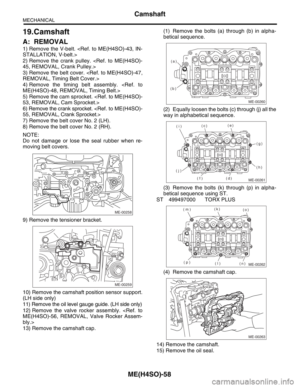
13) Remove the camshaft cap.(1) Remove the bolts (a) through (b) in alpha-
betical sequence.
(2) Equally loosen the bolts (c) through (j) all the
way in alphabetical sequence.
(3) Remove the bolts (k) through (p) in alpha-
betical sequence using ST.
ST 499497000 TORX PLUS
(4) Remove the camshaft cap.
14) Remove the camshaft.
15) Remove the oil seal.
ME-00258
ME-00259
ME-00260
(b)(a)
ME-00261
(c)(e)
(g)
(h)
(d) (f) (j)(i)
ME-00262
(k)
(o)
(n) (l) (p) (m)
ME-00263